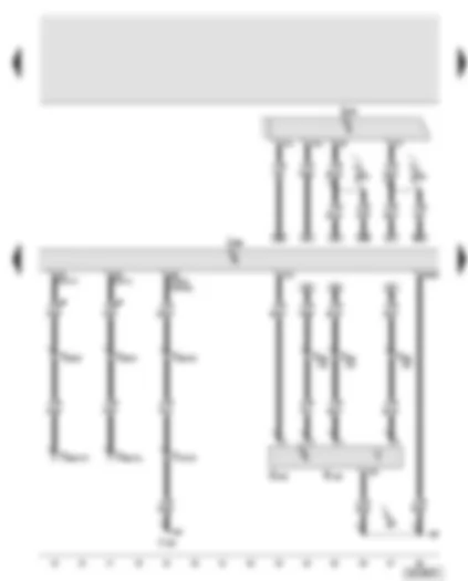
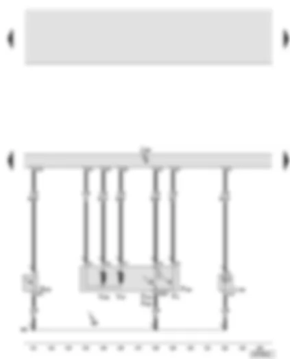
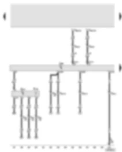
Wiring Diagram AUDI A8 2003 - Door control unit - driver's side - electric window thermo-fuse - card system for Italy (telepass)
 https://portal-diagnostov.com/license.html
Automotive Electricians Portal FZCO
Automotive Electricians Portal FZCO
https://portal-diagnostov.com/license.html
https://portal-diagnostov.com/license.html
Automotive Electricians Portal FZCO
Automotive Electricians Portal FZCO
| J386 | Door control unit, driver's side |
| R11 | Aerial |
| S43 | Electric window thermo-fuse |
| S133 | Fuse 3, 150 A, in luggage compartment, rear right |
| SB23 | Fuse -23- on fuse box |
| SB38 | Fuse -38- on fuse box |
| SB39 | Fuse -39- on fuse box |
| SB41 | Fuse -41- on fuse box |
| T1m | Single connector, for telepass aerial, in driver's door |
| T2u | 2-pin connector, for telepass supply, in driver's door |
| T20a | 20-pin connector, black, A pillar, left |
| 369 | Earth connection -4-, in main wiring harness |
| B298 | Positive (+) connection -2- (30), in main wiring harness |
| B302 | Positive (+) connection -6- (30), in main wiring harness |
| B303 | Positive (+) connection -7- (30), in main wiring harness |
| * | Only models for Italy |
| ** | In exterior mirror, driver's side |
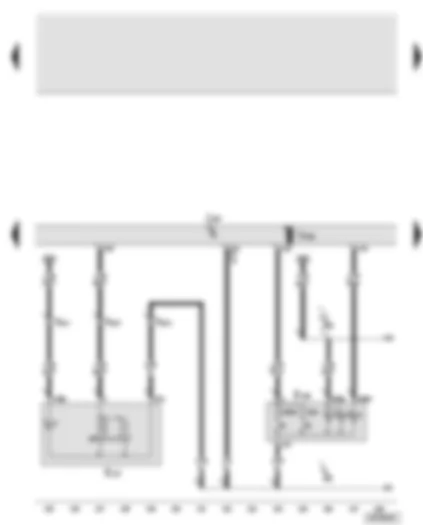
Wiring Diagram AUDI A8 2003 - Door control unit - driver's side - exterior door handle touch sensor - driver's side - driver's side aerial for entry and start authorisation - entry and start authorisation control unit
| G415 | Exterior door handle touch sensor, driver's side |
| J136 | Seat adjustment with memory control unit |
| J386 | Door control unit, driver's side |
| J518 | Entry and start authorisation control unit |
| R134 | Driver's side aerial for entry and start authorisation |
| T17s | 17-pin connector, brown, under driver's seat |
| T20a | 20-pin connector, black, A pillar, left |
| T46a | 46-pin connector, black, CAN separating connector, left |
| 267 | Earth connection -2-, in door wiring harness - driver's side |
| B371 | Connection -1- (aerial), in main wiring harness |
| B372 | Connection -2- (aerial), in main wiring harness |
| • | CAN bus (data wire) |
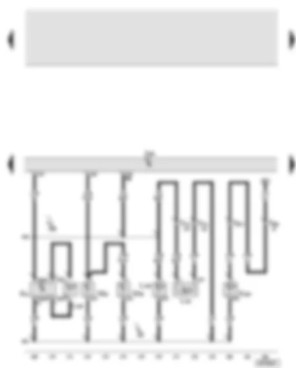
Wiring Diagram AUDI A8 2003 - Door control unit - driver's side - exterior door handle central locking button - driver's side - front left exterior door handle illumination - central locking lock unit - driver's side
| E369 | Exterior door handle central locking button, driver's side |
| F2 | Door contact switch, driver's side |
| F131 | Central locking actuator, front left |
| F220 | Central locking lock unit, driver's side |
| F241 | Contact switch in lock cylinder, driver's side |
| F243 | Central locking actuator (Safe), driver's door |
| J386 | Door control unit, driver's side |
| L162 | Front left exterior door handle illumination |
| V56 | Central locking motor, driver's door |
| V161 | Central locking motor (Safe), driver's door |
| 267 | Earth connection -2-, in door wiring harness - driver's side |
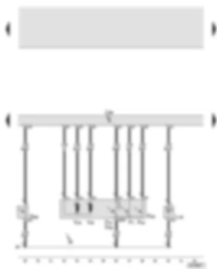
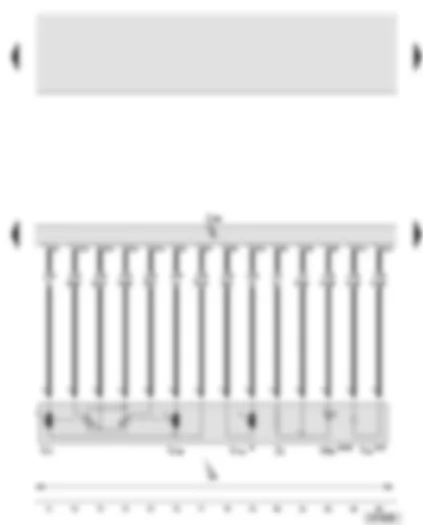
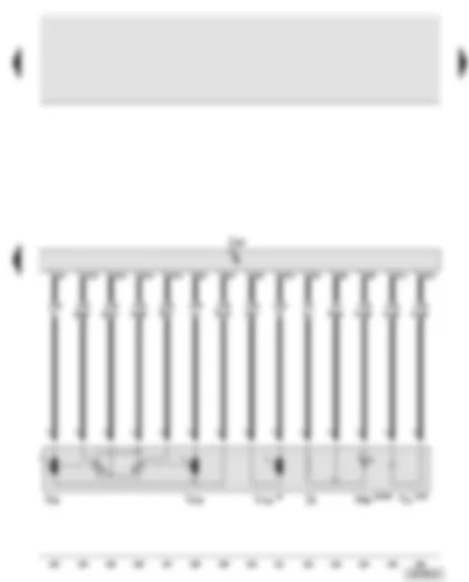
Wiring Diagram AUDI A8 2003 - Door control unit - driver's side - electric window switches - electric window motor - driver's side
| E40 | Front left electric window switch |
| E53 | Rear left electric window switch, driver's door |
| E55 | Rear right electric window switch, driver's door |
| E81 | Front right electric window switch, driver's door |
| J386 | Door control unit, driver's side |
| T17r | 17-pin connector, in driver's door |
| V147 | Electric window motor, driver's side |
Wiring Diagram AUDI A8 2003 - Door control unit - driver's side - mirror adjustment switch - mirror adjustment change-over switch - mirror with folding function - adjustment switch - interior monitor switch - alarm system off switch - interior monitor sender/receiver module 1
| E43 | Mirror adjustment switch |
| E48 | Mirror adjustment change-over switch |
| E168 | Mirror with folding function, adjustment switch |
| E183 | Interior monitor switch |
| E217 | Alarm system off switch |
| G303 | Interior monitor sender/receiver module 1 |
| J386 | Door control unit, driver's side |
| J528 | Roof electronics control unit |
| T8f | 8-pin connector, black, near interior light, front |
| T17r | 17-pin connector, in driver's door |
| T46b | 46-pin connector, black, CAN separating connector, right |
| 304 | Earth connection -3-, in door wiring harness - driver's side |
| • | CAN bus (data wire) |
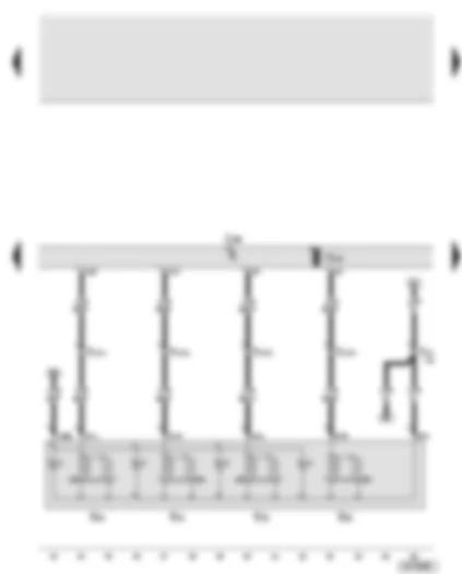
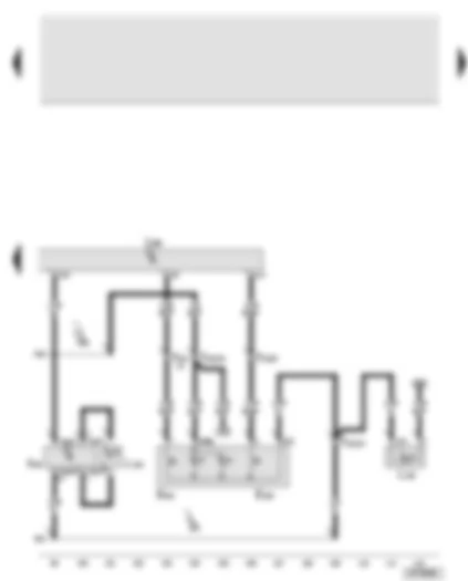
Wiring Diagram AUDI A8 2003 - Door control unit - driver's side - mirror adjustment motors - heated exterior mirror - driver's side - automatic anti-dazzle exterior mirror - driver's side - entry light in exterior mirror
| J386 | Door control unit, driver's side |
| V17 | Mirror adjustment motor, driver's side |
| V121 | Folding mirror motor, driver's side |
| V149 | Mirror adjustment motor, driver's side |
| Y20 | Automatic anti-dazzle exterior mirror, driver's side |
| W52 | Entry light in exterior mirror, driver's side |
| Z4 | Heated exterior mirror, driver's side |
| 304 | Earth connection -3-, in door wiring harness - driver's side |
| * | Mirror with retraction function |
| ** | With automatic anti-dazzle exterior mirror |
| *** | With entry light in exterior mirror |
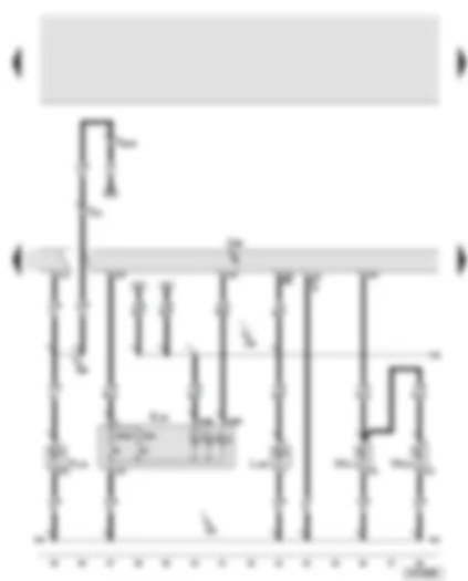
Wiring Diagram AUDI A8 2003 - Door control unit - driver's side - central locking warning lamp -SAFE- - interior locking switch - driver's side - door warning lamp - driver's side - front left entry light
| E150 | Interior locking switch, driver's side |
| J386 | Door control unit, driver's side |
| K133 | Central locking warning lamp -SAFE- |
| L108 | Door opening illumination, driver's side |
| T2i | 2-pin connector, in driver's door |
| T20a | 20-pin connector, black, A pillar, left |
| W30 | Door warning lamp, driver's side |
| W31 | Front left entry light |
| 304 | Earth connection -3-, in door wiring harness - driver's side |
| R52 | Connection (58s), in door wiring harness - driver's side |
| R66 | Positive (+) connection (central locking), in door wiring harness - driver's side |
| * | Switch earth output |
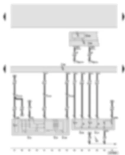
Wiring Diagram AUDI A8 2003 - Door control unit - driver's side - fuel tank flap release button - rear lid remote release button - illumination of driver's door storage compartment
| A20 | Ambient lighting voltage converter, driver's door |
| E233 | Rear lid remote release button |
| E319 | Fuel tank flap release button |
| J386 | Door control unit, driver's side |
| L160 | Illumination of driver's door storage compartment |
| L164 | Driver's door ambient lighting |
| T2ae | 2-pin connector, on ambient lighting voltage converter |
| T2af | 2-pin connector, on ambient lighting voltage converter |
| T17p | 17-pin connector, in driver's door |
| 304 | Earth connection -3-, in door wiring harness - driver's side |
| R52 | Connection (58s), in door wiring harness - driver's side |
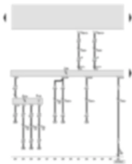
Wiring Diagram AUDI A8 2003 - Door control unit - front passenger's side - electric window fuse - front passenger's side
Wiring Diagram AUDI A8 2003 - Door control unit - front passenger's side - entry and start authorisation control unit - exterior door handle touch sensor - front passenger's side - front passenger's side aerial for entry and start authorisation
| G416 | Exterior door handle touch sensor, front passenger's side |
| J387 | Door control unit, front passenger's side |
| J518 | Entry and start authorisation control unit |
| J521 | Seat adjustment with memory control unit, front passenger |
| R135 | Front passenger's side aerial for entry and start authorisation |
| T17t | 17-pin connector, brown, under front passenger's seat |
| T20b | 20-pin connector, black, A pillar, right |
| T46b | 46-pin connector, black, CAN separating connector, right |
| 268 | Earth connection -2-, in door wiring harness - front passenger's side |
| B373 | Connection -3- (aerial), in main wiring harness |
| B374 | Connection -4- (aerial), in main wiring harness |
| • | CAN bus (data wire) |
Wiring Diagram AUDI A8 2003 - Door control unit - front passenger's side - central locking button - front right exterior door handle illumination - central locking lock unit - front passenger's side
| E370 | Exterior door handle central locking button, front passenger's side |
| F3 | Door contact switch, front passenger's side |
| F133 | Central locking actuator, front right |
| F221 | Central locking lock unit, front passenger's side |
| F244 | Central locking actuator (Safe), front passenger's door |
| J387 | Door control unit, front passenger's side |
| L163 | Front right exterior door handle illumination |
| V57 | Central locking motor, front passenger's door |
| V162 | Central locking motor (Safe), front passenger's door |
| 268 | Earth connection -2-, in door wiring harness - front passenger's side |
Wiring Diagram AUDI A8 2003 - Door control unit - front passenger's side - electric window switch in front passenger's door - interior locking switch - front passenger's side
| E107 | Electric window switch, in front passenger's door |
| E198 | Interior locking switch, front passenger's side |
| J387 | Door control unit, front passenger's side |
| T4e | 4-pin connector, in front passenger's door |
| V148 | Electric window motor, front passenger's side |
| 303 | Earth connection -3-, in door wiring harness - front passenger's side |
| R53 | Connection (58s), in door wiring harness - front passenger's side |
| * | Switch earth output |
Wiring Diagram AUDI A8 2003 - Door control unit - front passenger's side - central locking warning lamp -SAFE- (front passenger) - front right entry light - door warning lamp - front passenger's side - illumination of front passenger's door storage compartment
| A21 | Ambient lighting voltage converter, front passenger's door |
| J387 | Door control unit, front passenger's side |
| K204 | Central locking warning lamp -SAFE-, front passenger |
| L109 | Door opening illumination, front passenger's side |
| L161 | Illumination of front passenger's door storage compartment |
| L165 | Ambient lighting for front passenger's door |
| T2k | 2-pin connector, in front passenger's door |
| T2ae | 2-pin connector, on ambient lighting voltage converter |
| T2af | 2-pin connector, on ambient lighting voltage converter |
| T17q | 17-pin connector, in front passenger's door |
| T20b | 20-pin connector, black, A pillar, right |
| W32 | Front right entry light |
| W36 | Door warning lamp, front passenger's side |
| 303 | Earth connection -3-, in door wiring harness - front passenger's side |
| R53 | Connection (58s), in door wiring harness - front passenger's side |
Wiring Diagram AUDI A8 2003 - Door control unit - front passenger's side - mirror adjustment motors - heated exterior mirror - front passenger's side - entry light in exterior mirror - front passenger's side
| J387 | Door control unit, front passenger's side |
| V25 | Mirror adjustment motor, front passenger's side |
| V122 | Folding mirror motor, front passenger's side |
| V150 | Mirror adjustment motor, front passenger's side |
| Y21 | Automatic anti-dazzle exterior mirror, front passenger's side |
| W53 | Entry light in exterior mirror, front passenger's side |
| Z5 | Heated exterior mirror, front passenger's side |
| * | Mirror with retraction function |
| ** | With automatic anti-dazzle exterior mirror |
| *** | With entry light in exterior mirror |
Wiring Diagram AUDI A8 2003 - Rear left door control unit - rear left exterior door handle touch sensor - entry and start authorisation - driver's side rear aerial
| G417 | Exterior door handle touch sensor, rear left |
| J388 | Door control unit, rear left |
| R155 | Entry and start authorisation, driver's side rear aerial |
| T20c | 20-pin connector, black, B pillar, left |
| T46a | 46-pin connector, black, CAN separating connector, left |
| 367 | Earth connection -2-, in main wiring harness |
| • | CAN bus (data wire) |
Wiring Diagram AUDI A8 2003 - Rear left door control unit - rear left exterior door handle illumination - rear left exterior door handle central locking button - rear left central locking lock unit
| E371 | Exterior door handle central locking button, rear left |
| F10 | Rear left door contact switch |
| F132 | Central locking actuator, rear left |
| F222 | Central locking lock unit, rear left |
| F245 | Central locking actuator (Safe), rear left door |
| J388 | Door control unit, rear left |
| L168 | Rear left exterior door handle illumination |
| V115 | Central locking motor, rear left door |
| V163 | Central locking motor (Safe), rear left door |
| 350 | Earth connection -2-, in rear left door wiring harness |
| * | Switch earth output |
| ** | Models without entry and start authorisation |
| *** | Models with entry and start authorisation |
Wiring Diagram AUDI A8 2003 - Rear left door control unit - rear left entry light - rear left door warning lamp - rear left interior locking switch
| A22 | Ambient lighting voltage converter, rear left door |
| E273 | Rear left interior locking switch |
| J388 | Door control unit, rear left |
| L110 | Door opening illumination, rear left |
| L166 | Ambient lighting for rear left door |
| T2ae | 2-pin connector, on ambient lighting voltage converter |
| T2af | 2-pin connector, on ambient lighting voltage converter |
| W33 | Rear left entry light |
| W37 | Door warning lamp, rear left |
| 408 | Earth connection -3-, in rear left door wiring harness |
| R54 | Connection (58s), in rear left door wiring harness |
| * | Switch earth output |
Wiring Diagram AUDI A8 2003 - Rear left door control unit - rear left electric window switch (in door) - rear left ashtray light bulb - rear left electric window motor - illumination of rear left door storage compartment
| E52 | Rear left electric window switch, in door |
| J388 | Door control unit, rear left |
| L48 | Rear ashtray light bulb, left |
| L170 | Illumination of rear left door storage compartment |
| T4f | 4-pin connector, in rear left door |
| T4h | 4-pin connector, in rear left door |
| V26 | Electric window motor, rear left |
| 408 | Earth connection -3-, in rear left door wiring harness |
| R54 | Connection (58s), in rear left door wiring harness |
Wiring Diagram AUDI A8 2003 - Rear right door control unit - rear right exterior door handle touch sensor - entry and start authorisation - front passenger's side rear aerial
| G418 | Exterior door handle touch sensor, rear right |
| J389 | Door control unit, rear right |
| R156 | Entry and start authorisation, front passenger's side rear aerial |
| T20d | 20-pin connector, black, B pillar, right |
| T46b | 46-pin connector, black, CAN separating connector, right |
| 368 | Earth connection -3-, in main wiring harness |
| • | CAN bus (data wire) |
Wiring Diagram AUDI A8 2003 - Rear right door control unit - rear right exterior door handle central locking button - rear right central locking lock unit
| E372 | Exterior door handle central locking button, rear right |
| F11 | Rear right door contact switch |
| F134 | Central locking actuator, rear right |
| F223 | Central locking lock unit, rear right |
| F246 | Central locking actuator (Safe), rear right door |
| J389 | Door control unit, rear right |
| L169 | Rear right exterior door handle illumination |
| V97 | Central locking motor, rear right door |
| V164 | Central locking motor (Safe), rear right door |
| 351 | Earth connection -2-, in rear right door wiring harness |
| * | Switch earth output |
| ** | Models without entry and start authorisation |
| *** | Models with entry and start authorisation |
Wiring Diagram AUDI A8 2003 - Rear right door control unit - rear right entry light - rear right door warning lamp - rear right interior locking switch - rear right door opening illumination - ambient lighting for rear right door
| A23 | Ambient lighting voltage converter, rear right door |
| E274 | Rear right interior locking switch |
| J389 | Door control unit, rear right |
| L111 | Door opening illumination, rear right |
| L167 | Ambient lighting for rear right door |
| T2ae | 2-pin connector, on ambient lighting voltage converter |
| T2af | 2-pin connector, on ambient lighting voltage converter |
| W34 | Rear right entry light |
| W38 | Door warning lamp, rear right |
| 409 | Earth connection -3-, in rear right door wiring harness |
| R55 | Connection (58s), in rear right door wiring harness |
| * | Switch earth output |
Wiring Diagram AUDI A8 2003 - Rear right door control unit - rear right electric window motor - rear right electric window switch (in door) - rear right ashtray light bulb - illumination of rear right door storage compartment
| E54 | Rear right electric window switch, in door |
| E157 | Adjustable front passenger's seat switch |
| J389 | Door control unit, rear right |
| L49 | Rear ashtray light bulb, right |
| L171 | Illumination of rear right door storage compartment |
| T4g | 4-pin connector, in rear right door |
| T4i | 4-pin connector, in rear right door |
| V27 | Electric window motor, rear right |
| 409 | Earth connection -3-, in rear right door wiring harness |
| R55 | Connection (58s), in rear right door wiring harness |
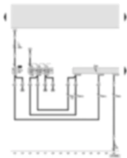
Wiring Diagram AUDI A8 2003 - Convenience system central control unit - fuses
| J329 | Terminal 15 voltage supply relay |
| J393 | Convenience system central control unit |
| S132 | Fuse 2, 60 A, in luggage compartment, rear right |
| SF1 | Fuse -1- on fuse box |
| SF2 | Fuse -2- on fuse box |
| SF3 | Fuse -3- on fuse box |
| T46b | 46-pin connector, black, CAN separating connector, right |
| 378 | Earth connection -13-, in main wiring harness |
| B165 | Positive (+) connection -2- (15), in interior wiring harness |
| B273 | Positive (+) connection (15), in main wiring harness |
| B299 | Positive (+) connection -3- (30), in main wiring harness |
| B316 | Positive (+) connection -2- (30a), in main wiring harness |
| • | CAN bus (data wire) |
Wiring Diagram AUDI A8 2003 - Convenience system central control unit - rear lid - tank filler flap locking motor - switch in lock cylinder for rear lid anti-theft alarm system/central locking system - release button for rear lid lock cylinder - central locking motor - rear lid - alarm horn
| F123 | Rear lid contact switch for anti-theft alarm |
| F124 | Switch in lock cylinder for rear lid anti-theft alarm system/central locking system |
| F248 | Release button for rear lid lock cylinder |
| H12 | Alarm horn |
| J393 | Convenience system central control unit |
| S133 | Fuse 3, 150 A, in luggage compartment, rear right |
| V53 | Central locking motor, rear lid |
| V155 | Tank filler flap locking motor |
| 366 | Earth connection -1-, in main wiring harness |
| 376 | Earth connection -11-, in main wiring harness |
| 378 | Earth connection -13-, in main wiring harness |
| B272 | Positive (+) connection (30), in main wiring harness |
| B300 | Positive (+) connection -4- (30), in main wiring harness |
| B303 | Positive (+) connection -7- (30), in main wiring harness |
Wiring Diagram AUDI A8 2003 - Convenience system central control unit - rear lid electric release motor - rear lid control unit - power latching system limit switch - luggage compartment - anti-theft/tilt system control unit - power latching control unit
| E406 | Rear lid close button, in luggage compartment |
| F332 | Power latching system limit switch, luggage compartment unlocked |
| F333 | Power latching system limit switch, luggage compartment locked |
| J393 | Convenience system central control unit |
| J529 | Anti-theft/tilt system control unit |
| J605 | Rear lid control unit |
| J657 | Power latching control unit |
| T5c | 5-pin connector, in luggage compartment, for rear lid power latching system |
| V120 | Rear lid lock motor |
| V254 | Rear lid electric release motor |
| 376 | Earth connection -11-, in main wiring harness |
| 378 | Earth connection -13-, in main wiring harness |
| 383 | Earth connection -18-, in main wiring harness |
| B476 | Connection -12-, in main wiring harness |
| B487 | Connection -23-, in main wiring harness |
Wiring Diagram AUDI A8 2003 - Convenience system central control unit - luggage compartment light - boot lid light - rear left and rear right footwell illumination
| J393 | Convenience system central control unit |
| L106 | Footwell illumination, rear left |
| L107 | Footwell illumination, rear right |
| T17h | 17-pin connector, grey, under driver's seat |
| T17i | 17-pin connector, grey, under front passenger's seat |
| W18 | Luggage compartment light, left |
| W35 | Luggage compartment light, right |
| W51 | Boot lid light |
| 367 | Earth connection -2-, in main wiring harness |
| 368 | Earth connection -3-, in main wiring harness |
| 371 | Earth connection -6-, in main wiring harness |
| 377 | Earth connection -12-, in main wiring harness |
| 378 | Earth connection -13-, in main wiring harness |
| B476 | Connection -12-, in main wiring harness |
| M43 | Connection -3-, in driver's seat wiring harness |
| M53 | Connection -3-, in front passenger's seat wiring harness |
Wiring Diagram AUDI A8 2003 - Onboard power supply control unit - bonnet contact switch - left footwell light - centre console illumination - right footwell light
| F266 | Bonnet contact switch |
| F329 | Bonnet contact switch -2- |
| J519 | Onboard power supply control unit |
| L150 | Centre console illumination |
| SC18 | Fuse -18- on fuse box |
| T8b | 8-pin connector, black, behind dash panel, right |
| W9 | Left footwell light |
| W10 | Right footwell light |
| 81 | Earth connection -1-, in dash panel wiring harness (glove box) |
| 369 | Earth connection -4-, in main wiring harness |
| 372 | Earth connection -7-, in main wiring harness |
| 375 | Earth connection -10-, in main wiring harness |
| B465 | Connection -1-, in main wiring harness |
| * | Models without additional lighting equipment |
| ** | Models with additional lighting equipment |
AUDI A8 2003 Control units overview
Control units overview | | | | Roof electronics control unit -J528- |
| Audi A8 | Fitting Locations | No. 804 / 2 |
|
| Audi A8 | Fitting Locations | No. 804 / 3 |
|
| q | Connector assignment, 20-pin connector -T20e- |
Front information display and operating unit control unit -J523-
| | | Display unit for front information display and operating unit control unit -J685- | | | |
| In centre dash panel -Item 1- | | | |
Steering column electronics control unit -J527-
| | | Near steering column, behind steering wheel | | Driver side door control unit -J386-, front passenger door control unit -J387- | | | |
| In front passenger door -arrow- | | | |
Connector assignment:
| | | Pin connector front door: |
| A - | 32-pin connector (connector A), white |
| B - | 16-pin connector (connector B), brown |
| C - | 12-pin connector (connector C), black |
| D - | 10-pin connector, black (connector D), black |
| B - | 16-pin connector (connector A), brown |
| C - | 12-pin connector (connector B), black |
| D - | 10-pin connector (connector C), black |
Power latching control unit for driver door -J760-, power latching control unit for front passenger door -J761-
AUDI A8 2003 Onboard supply control unit 2 -J520-
Location: | | Under carpet of the front passenger seat -arrow- |
| | Connector assignment:
| A - | 40-pin connector, on control unit |
| B - | 40-pin connector, black, on wiring harness |
Roof electronics control unit -J528-
| | | The roof electronics control unit -J528- in front roof module contains: | | 1 - | Interior monitor send and receive module 1 -G303- | | 2 - | Garage door operating unit -E284- | | 3 - | Telematics operating unit -E264- | | 1, 4, 5 - | Microphone unit in front roof module -R164- | | 4 - | Interior monitor send and receive module 2 -G305- | | | |
Airbag control unit -J234-
| | | On the front centre tunnel -Item 1- | | | |
Connector assignment:
| - | Airbag control unit -J234- |
| A - | 84-pin connector, yellow |
| - | 75-pin connector, yellow |
Seat and steering column adjustment control unit with memory -J136-
| | | In lower driver seat -Item 2-, coupling station driver seat -Item 1- | | | |
Connector assignment:
| A - | 12-pin connector -connector ST5-, black |
| B - | 12-pin connector -connector ST4-, black |
| C - | 32-pin connector -connector ST6-, blue |
| D - | 32-pin connector -connector ST7-, green |
Entry and start authorisation control unit -J518-
| | | Location left-hand drive: | | Under carpet of the driver seat -arrow- | | Location right-hand drive: | | Under carpet of the front passenger seat -arrow-. | | | |
Connector assignment:
| A - | 81-pin connector -connector A-, black |
| B - | 6-pin connector -connector B-, black |
Onboard power supply control unit -J519-
| | | Behind the shelf on the driver's side, on relay and fuse holder behind the dash panel, left -arrow- | | | |
Connector assignment:
| A - | 32-pin connector, -T32a- (connector C), grey |
| B - | 23-pin connector -T23- (connector B), black |
| C - | 10-pin connector, -T10p- (connector A), black |
Headlight range control, control unit -J431-
| | Connector assignment:
| A - | 26-pin connector, yellow |
ABS control unit -J104-
| A - | 42-pin connector, black |
Control unit in dash panel insert -J285-
| A - | 32 pin connector -T32-, blue |
Wiper motor control unit -J400-
| | | In plenum chamber on windscreen wiper motor -arrow- | | | |
Automatic gearbox control unit -J217-, gearbox 09E/09L
| A - | 16-pin connector -T16c-, black |
Automatic gearbox control unit -J217-, gearbox 01J/01T
| A - | 20-pin connector -T20e-, black |
Data bus diagnostic interface -J533-
| | | Adaptive suspension control unit -J197- | | | |
| Behind the glove box -Item 3- | | 1 - | Front information display and operating unit control unit -J523- | | 2 - | Data bus diagnostic interface -J533- | | 3 - | Adaptive suspension control unit -J197- | | | |
Connector assignment:
| A - | 81-pin connector (connector A), black |
| B - | 40-pin connector (connector B), black |
AUDI A8 2003 Engine control unit -J623-, engine control unit 2 -J624-
| Engine control unit -1- with electronics box -2- in plenum chamber |
| Engine control unit2 -J624-, installed under or next to engine control unit -J623-, depending on equipment |
| Adaptive cruise control unit -J428- |
| | | Behind the front bumper, lower | | | |
Connector assignment:
| A - | 12-pin connector, black |
Garage door operation control unit -J530-
| Behind the front bumper, left |
| | | 1 - | 4-pin connector, black -T4bi- |
| 2 - | Garage door operation control unit -J530- |

 Čeština
 Dansk
Dansk Deutsch
 Ελληνικά
 English
 Español
 Suomi
Suomi Français
 Français
 עברית
עברית Hrvatski
 Magyar
 Italiano
 日本語
日本語 한국어
한국어 Nederlands
 Polski
 Português
 Português
 Română
 Русский
 Slovenčina
 Slovenščina
 Svenska
 Türkçe
 中文 (中国)


 - rear left ashtray light bulb - rear left electric window motor - illumination of rear left door storage compartment")


 - rear right ashtray light bulb - illumination of rear right door storage compartment")


")


 on fuse holder, on right in luggage compartment, from model year 2004")
 on fuse holder, on left in luggage compartment, up to model year 2003")
 on fuse holder, on left in luggage compartment, from model year 2004")


