COOLING FAN
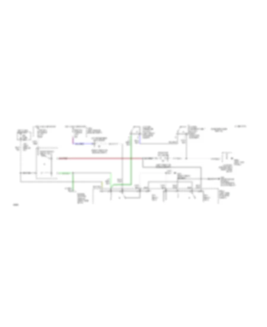
Cooling Fan Wiring Diagram for Toyota Celica GT 1994
List of elements for Cooling Fan Wiring Diagram for Toyota Celica GT 1994:
- (left front of engine compt)
- (right front of engine compt)
- 1994 vftc c
- A/c condenser fan motor
- A/c high pressure switch (left front of engine compt)
- Air conditioning system (a/c magnetic clutch relay)
- Case grounded for 1.8l
- Cds fan fusible link 30a
- Engine control module (right side of i/p)
- Fan relay no. 2
- Fan relay no. 3
- G101 (right front fender)
- G200 (left kick panel) junction connector 9 (right side of i/p)
- Hot in run or start
- Ign fuse 7.5a
- J/b 1 (left side of i/p)
- J/b 2 (left side of engine compt)
- R/b 5 (left side of engine compt)
- Radiator fan motor
- Radiator fan relay no. 1
- Rdi fan fusible link 30a
- Water temperature switch (right radiator support)
 Čeština
 Dansk
Dansk Deutsch
 Ελληνικά
 English
 English
 Español
 Suomi
Suomi Français
 עברית
עברית Hrvatski
 Magyar
 Italiano
 日本語
日本語 한국어
한국어 Nederlands
 Polski
 Português
 Português
 Română
 Русский
 Slovenčina
 Slovenščina
 Svenska
 Türkçe
 中文 (中国)
 Français