DEFOGGERS
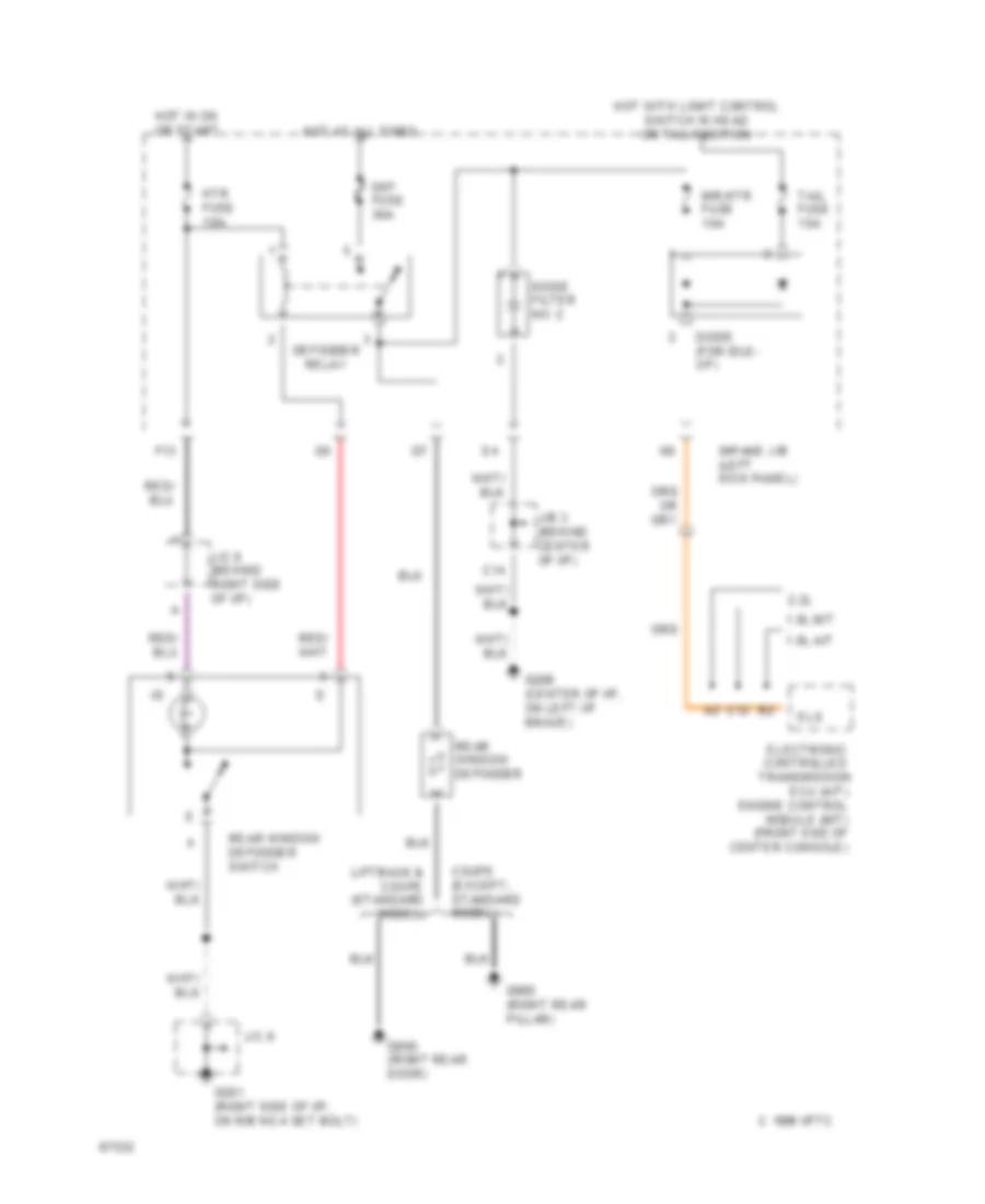
Defogger Wiring Diagram for Toyota Celica GT 1994
List of elements for Defogger Wiring Diagram for Toyota Celica GT 1994:
- 1.8l a/t
- 1.8l m/t
- 2.2l
- C 1995 vftc
- C12
- C14
- Coupe (except- standard model)
- Def fuse 30a
- Defogger relay
- Diode (for idle- up)
- Ecu (a/t) engine control module (m/t) (front end of center console)
- Electronic controlled
- Els
- F13
- G201 (right side of i/p, on r/b no.4 set bolt)
- G206 (center of i/p, on left i/p brace)
- G800 (right rear door)
- G905 (right rear pillar)
- Hot at all times
- Hot in on or start
- Hot with light control switch in head or tail position
- Htr fuse 10a
- Impane j/b (left kick panel)
- J/b 3 (behind center of i/p)
- J/c 6 (behind right side of i/p)
- J/c 9
- Liftback & coupe (standard model)
- Mir-htr fuse 10a
- Noise filter no. 2
- Rear window defogger
- Rear window defogger switch
- Tail fuse 15a
- Transmission
 Čeština
 Dansk
Dansk Deutsch
 Ελληνικά
 English
 Español
 Suomi
Suomi Français
 Français
 עברית
עברית Hrvatski
 Magyar
 Italiano
 日本語
日本語 한국어
한국어 Nederlands
 Polski
 Português
 Português
 Română
 Русский
 Slovenčina
 Slovenščina
 Svenska
 Türkçe
 中文 (中国)
 English