ENGINE PERFORMANCE
1.8L
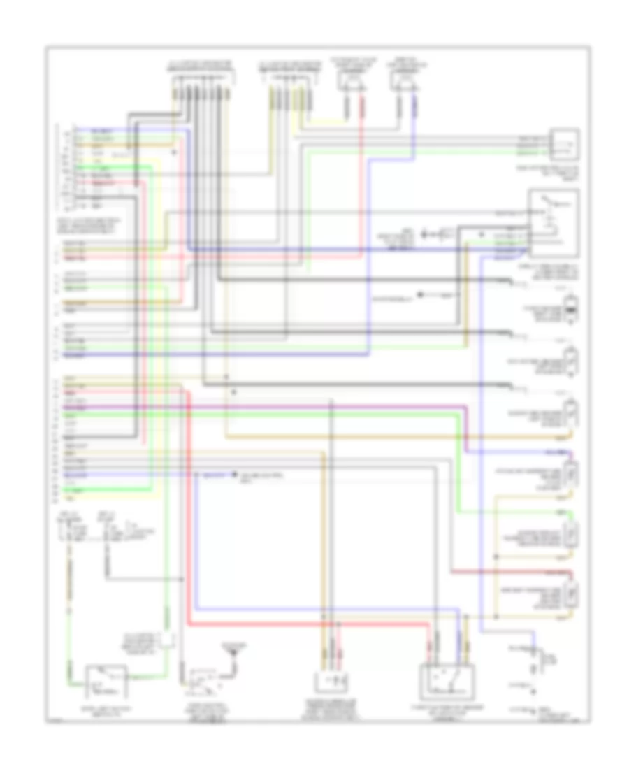
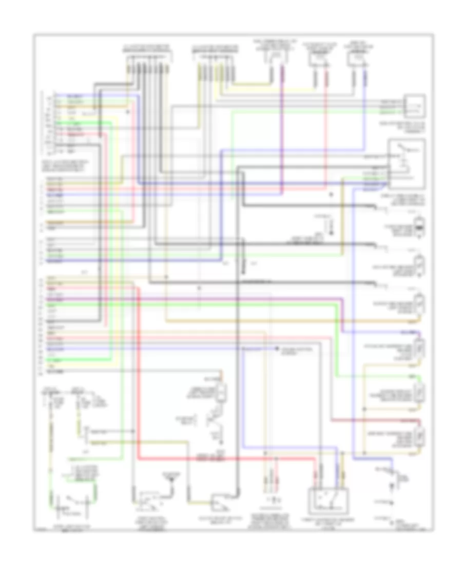
1.8L, Engine Performance Wiring Diagrams, A/T (1 of 2) for Toyota Celica GT 1995
 https://portal-diagnostov.com/license.html
Automotive Electricians Portal FZCO
Automotive Electricians Portal FZCO
https://portal-diagnostov.com/license.html
https://portal-diagnostov.com/license.html
Automotive Electricians Portal FZCO
Automotive Electricians Portal FZCO
List of elements for 1.8L, Engine Performance Wiring Diagrams, A/T (1 of 2) for Toyota Celica GT 1995:
- #10
- #20
- (behind center of console)
- A/c amplifier
- A10
- A11
- A12
- A13
- A14
- A15
- A16
- A17
- A18
- A19
- A20
- A21
- A22
- A23
- A24
- A25
- A26
- Aca
- Act
- B/k
- B10
- B11
- B12
- B13
- B14
- B15
- B16
- Batt
- C10
- C11
- C12
- C13
- C14
- C15
- C16
- C17
- C18
- C19
- C20
- C21
- C22
- Distributor
- E01
- E02
- Efi fuse 15a
- Efi main relay (r/b #2)
- Egr
- Els
- Engine and electronic controlled transmission electronic control module (ecm)
- G100 (left front fender)
- G131 (intake manifold)
- Gauge fuse 10a
- Hot at all times
- Hot in run
- Hot in start or run
- Hot with defog on
- Hot with light sw on
- I/p junction block
- Idl
- Idle-up diode
- Ig+
- Ig-
- Igf
- Ign fuse 7.5a
- Igniter
- Ignition coil
- Igt
- Injector #1
- Injector #2
- Injector #3
- Injector #4
- Instrument cluster
- Isc
- Iscc
- Isco
- Knk
- Mal- func ind
- Mir-htr fuse 10a
- Nca
- Ne-
- Nsw
- Ox1
- Ox2
- Pim
- Pnk
- R/b #2 (left side of engine compt)
- Red
- Spd
- Speedo
- Sta
- Tail fuse 15a
- Te1
- Te2
- Tha
- Thg
- Thw
- Vehicle speed sensor (rear of engine)
- Vta
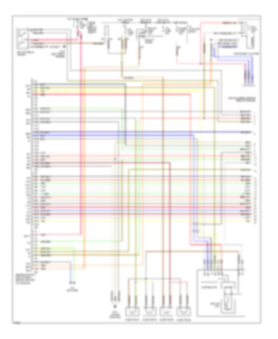
1.8L, Engine Performance Wiring Diagrams, A/T (2 of 2) for Toyota Celica GT 1995
List of elements for 1.8L, Engine Performance Wiring Diagrams, A/T (2 of 2) for Toyota Celica GT 1995:
- A/c idle-up valve (right side of engine)
- Circuit opening relay (under front of center console)
- Cruise control ecu
- Data link connector #1 (left rear corner of engine compartment)
- Egr gas temperature sensor (center of engine)
- Egr vsv (top center of engine)
- Engine coolant temperature sensor (rear of engine)
- F11
- Fuel pump
- G201 (right side of i/p at r/b #4 set bolt)
- G904 (under left center pillar)
- Hot at all times
- Hot in start
- I/p junction block
- Idle air control valve (on throttle body)
- Ig-
- Intake air temperature sensor (in air cleaner)
- J2 junction connector (behind left side of i/p)
- J3 junction connector (behind front console)
- J4 junction connector (behind front console)
- Knock sensor (right side of engine)
- Main oxygen sensor (left side of engine)
- Manifold absolute pressure sensor (right rear side of engine compartment)
- Nca
- Ox1
- Ox2
- P/n
- Park/neutral position switch (left side of transmission)
- Pim
- Red
- St fuse 7.5a
- Starter relay
- Stop fuse 15a
- Stop light switch (behind i/p)
- Sub oxygen sensor (left side of engine)
- Te1
- Te2
- Throttle position sensor (on air intake assembly)
- Vf1
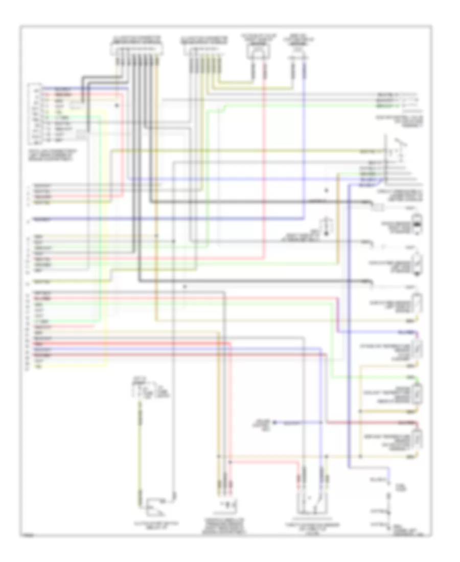
1.8L, Engine Performance Wiring Diagrams, M/T (1 of 2) for Toyota Celica GT 1995
List of elements for 1.8L, Engine Performance Wiring Diagrams, M/T (1 of 2) for Toyota Celica GT 1995:
- #10
- #20
- A/c amplifier
- Ac1
- Act
- B13
- Batt
- D10
- D11
- D12
- D13
- D14
- D15
- D16
- D17
- D18
- D19
- D20
- D21
- D22
- D23
- D24
- D25
- D26
- Distributor
- E01
- E02
- E10
- E11
- E12
- E13
- E14
- E15
- E16
- Efi fuse 15a
- Efi main relay (r/b #2)
- Egr
- Els
- Engine control module (ecm) (behind center
- F10
- F11
- F12
- G100 (left front fender)
- G131 (intake manifold)
- Gauge fuse 10a
- Hot at all times
- Hot in run
- Hot in start or run
- Hot with defog on
- Hot with light sw on
- I/p junction block
- Idl
- Idle-up diode
- Ig+
- Ig-
- Igf
- Ign fuse 7.5a
- Igniter
- Ignition coil
- Igt
- Injector #1
- Injector #2
- Injector #3
- Injector #4
- Instrument cluster
- Isc
- Knk
- Mal- func ind
- Mir-htr fuse 10a
- Nca
- Ne+
- Ne-
- Of console)
- Ox1
- Ox2
- Pim
- Pnk
- R/b #2 (left side of engine compt)
- Red
- Rsc
- Rso
- Spd
- Speedo
- Sta
- Tail fuse 15a
- Te1
- Te2
- Tha
- Thg
- Thw
- Vehicle speed sensor (rear of engine)
- Vta
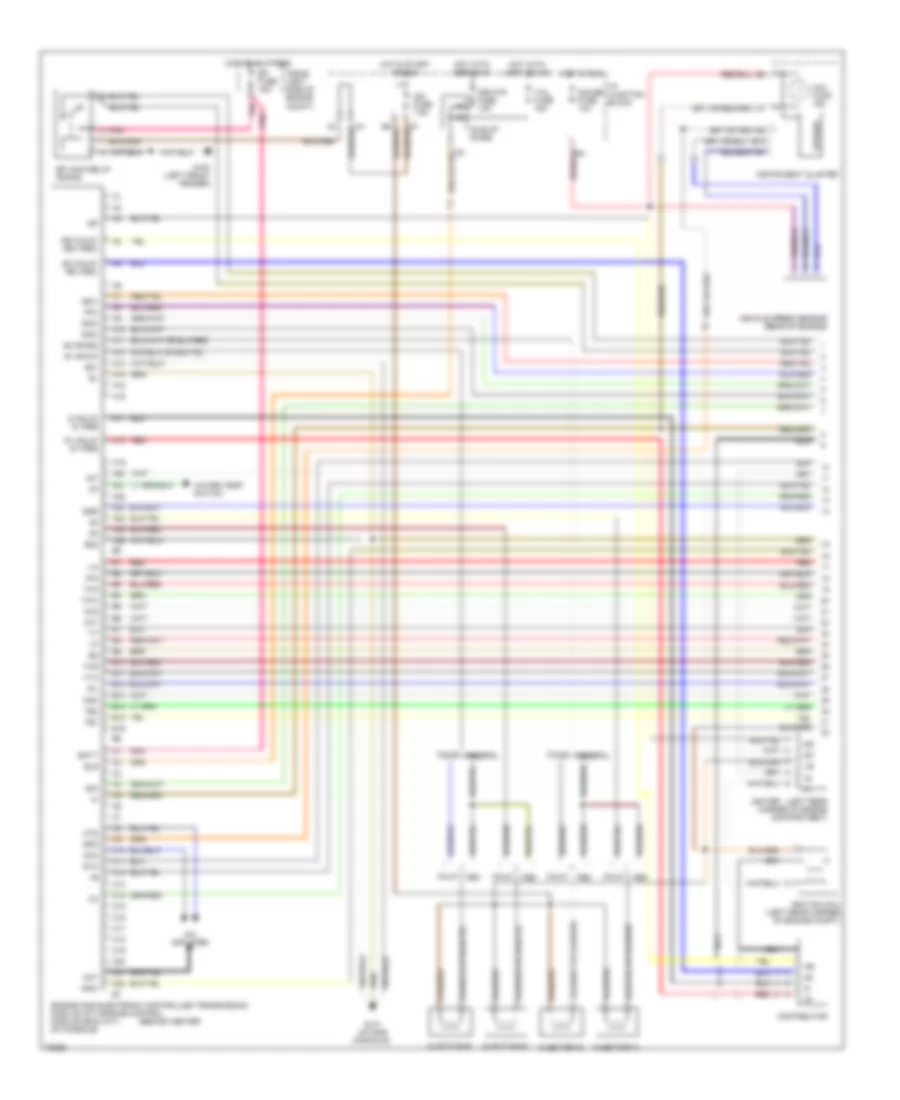
1.8L, Engine Performance Wiring Diagrams, M/T (2 of 2) for Toyota Celica GT 1995
List of elements for 1.8L, Engine Performance Wiring Diagrams, M/T (2 of 2) for Toyota Celica GT 1995:
- A/c idle-up valve (right side of engine)
- Circuit opening relay (under front of center console)
- Clutch start switch (below i/p)
- Coolant temperature sensor (rear of engine)
- Cruise control ecu
- Data link connector #1 (left rear corner of engine compartment)
- Egr gas temperature sensor (on air intake assembly)
- Egr vsv (top center of engine)
- Engine
- Fuel pump
- G201 (right side of i/p at r/b #4 set bolt)
- G904 (under left center pillar)
- Hot in start
- I/p fuse block
- Idle air control valve (on air intake assembly)
- Ig-
- Intake air temperature sensor (in air cleaner)
- J3 junction connector (behind front console)
- J4 junction connector (behind front console)
- Knock sensor (right side of engine)
- Main oxygen sensor (left side of engine)
- Manifold absolute pressure sensor (right rear side of engine compartment)
- Nca
- Ox1
- Ox2
- Pim
- Red
- St fuse 7.5a
- Sub oxygen sensor (left side of engine)
- Te1
- Te2
- Throttle position sensor (on throttle valve)
- Vf1
2.2L
2.2L, Engine Performance Wiring Diagrams (1 of 2) for Toyota Celica GT 1995
List of elements for 2.2L, Engine Performance Wiring Diagrams (1 of 2) for Toyota Celica GT 1995:
- #1 0r #10
- #2 or #20
- (behind center
- (left rear corner of engine compartment)
- A/c amplifier
- A10
- A11
- A12
- A13
- A14
- A15
- A16
- A17
- A18
- A19
- A20
- A21
- A22
- A23
- A24
- A25
- A26
- Aca
- Act
- Ats
- B/k
- B10
- B11
- B12
- B13
- B14
- B15
- B16
- Batt
- C10
- C11
- C12
- C13
- C14
- C15
- C16
- C17
- C18
- C19
- C20
- C21
- C22
- Calif
- Distributor
- E01
- E02
- Efi fuse 15a
- Efi main relay (r/b #2)
- Egr
- Els
- Engine and electronic controlled transmission module (a/t) engine control module (ecm) (m/t) of console)
- Fed
- Federal
- Fpu
- G (calif) g- (fed)
- G1 (calif) g+ (fed)
- G100 (left front fender)
- G131 (intake manifold)
- G2 (calif) ne- (fed)
- Gauge fuse 10a
- Hot at all times
- Hot in run
- Hot in start or run
- Hot with defog on
- Hot with light sw on
- I/p junction block
- Idl
- Idle-up diode
- Ig-
- Igf
- Ign fuse 7.5a
- Igniter
- Ignition coil (left rear corner of engine compt)
- Igt
- Injector #1
- Injector #2
- Injector #3
- Injector #4
- Instrument cluster
- Iscc
- Isco
- Iscv
- Knk
- Mal- func ind
- Mir-htr fuse 10a
- Nca
- Ne (calif) ne+ (fed)
- Nsw
- Ox1
- Ox2
- Pim
- Pnk
- R/b #2 (left side of engine compt)
- Red
- Spd
- Speedo
- Sta
- Tail fuse 15a
- Te1
- Te2
- Tha
- Thg
- Thw
- Vehicle speed sensor (rear of engine)
- Vta
- Water temp switch
2.2L, Engine Performance Wiring Diagrams (2 of 2) for Toyota Celica GT 1995
List of elements for 2.2L, Engine Performance Wiring Diagrams (2 of 2) for Toyota Celica GT 1995:
- A/c idle-up valve (right side of engine)
- A/t
- Circuit opening relay (under front of center console)
- Clutch start switch (below i/p)
- Cruise control system
- Data link connector #1 (left rear corner of engine compartment)
- Egr gas temperature sensor (center of engine)
- Egr vsv (top center of engine)
- Engine coolant temperature sensor (rear of engine)
- F11
- Fuel pressure-up vsv (top center of engine) (calif only)
- Fuel pump
- G100 (front of left front fender)
- G201 (right side of i/p at r/b #4 set bolt)
- G904 (under left center pillar)
- Hot at all times
- Hot in start
- I/p fuse block
- Idle air control valve (on air intake assembly)
- Ig-
- Intake air temperature sensor (in air cleaner)
- J2 junction connector (behind left side of i/p)
- J3 junction connector (behind front console)
- J4 junction connector (behind front console)
- Knock sensor (right side of engine)
- M/t
- Main oxygen sensor (left side of engine)
- Manifold absolute pressure sensor (right rear side of engine compartment)
- Nca
- Noise filter (left rear of engine compt)
- Ox1
- Ox2
- P/n
- Park/neutral position switch (left side of transmission)
- Pim
- Red
- St fuse 7.5a
- Starter relay
- Stop fuse 15a
- Stop light switch (behind i/p)
- Sub oxygen sensor (left side of engine)
- Te1
- Te2
- Throttle position sensor (on throttle valve)
- Vf1

 Čeština
 Dansk
Dansk Deutsch
 Ελληνικά
 English
 Español
 Suomi
Suomi Français
 Français
 עברית
עברית Hrvatski
 Magyar
 Italiano
 日本語
日本語 한국어
한국어 Nederlands
 Polski
 Português
 Português
 Română
 Русский
 Slovenčina
 Slovenščina
 Svenska
 Türkçe
 中文 (中国)