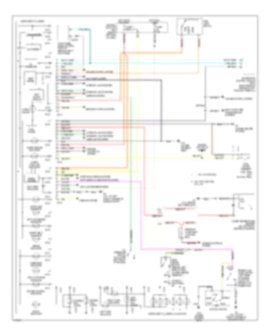
INSTRUMENT CLUSTER
Instrument Cluster Wiring Diagram for Mazda B2300 2003
List of elements for Instrument Cluster Wiring Diagram for Mazda B2300 2003:
- (at right kick panel) g9
- 2.3l
- 2.3l, 4.0l
- 2.3l, 4.ol
- 3.0l
- 3.0l w/ flex fuel
- 3.0l w/o flex fuel
- 3.0l, 4.0l
- 4wd hi indicator
- 4wd low range indicator
- Acc
- Air bag indi- cator
- Anti- slosh module
- Anti-lock brake indicator
- Anti-lock brakes system
- Anti-theft indicator
- Anti-theft system
- Body computer, transmissions systems
- Brake fluid level switch (left rear of engine compt, on brake fluid reservoir)
- Brake indicator
- C214
- C215
- C216
- Central junction box (behind left side of dash)
- Charge indi- cator
- Check engine indicator
- Check fuel cap indicator
- Check gauge
- Cruise control indicator
- Cruise control system
- Door ajar indicator
- Engine controls system
- Exterior lights system
- Four wheel drive control module (behind right kick panel)
- Fuel gauge
- Fuel gauge sensor
- Fuel tank unit (in fuel tank)
- Fuse 10a
- Fuse 11 7.5a
- G1 (4.0l: behind left headlight)
- G10 (under driver's seat)
- G3 (4.0l: at left front corner of engine compt)
- G8 (under center of dash)
- H-281b
- Head
- Headlights system
- High beam indi- cator
- Hot at all times
- Hot in run or start
- Ignition switch
- Instrument cluster
- Instrument cluster illumination
- Interior lights system
- Left turn indicator
- Lock
- Main light switch
- Nca
- Off
- Oil pressure
- Oil pressure switch (on lower left front of engine)
- Overdrive indicator
- Park
- Park brake switch (behind left side of dash, on park brake assembly)
- Powertrain control module (pcm) (right rear of engine compt, through firewall)
- Resistor (in battery junction box)
- Right turn indicator
- Run
- Safety belt indicator
- Speed- ometer
- Start
- Starting/charging system
- Tachometer
- Temp meter
- Voltmeter
- Warning system
- Water temperature sender (on top front center of engine)
 Čeština
 Dansk
Dansk Deutsch
 Ελληνικά
 English
 Español
 Suomi
Suomi Français
 Français
 עברית
עברית Hrvatski
 Magyar
 Italiano
 日本語
日本語 한국어
한국어 Nederlands
 Polski
 Português
 Português
 Română
 Русский
 Slovenčina
 Slovenščina
 Svenska
 Türkçe
 中文 (中国)
 English