INTERIOR LIGHTS
Courtesy Lamps Wiring Diagram for Toyota Celica GT 1994
 https://portal-diagnostov.com/license.html
Automotive Electricians Portal FZCO
Automotive Electricians Portal FZCO
https://portal-diagnostov.com/license.html
https://portal-diagnostov.com/license.html
Automotive Electricians Portal FZCO
Automotive Electricians Portal FZCO
List of elements for Courtesy Lamps Wiring Diagram for Toyota Celica GT 1994:
- B10
- B11
- C14
- Coupe
- D11
- Dcty
- Diode (left kick panel) (for door courtesy light)
- Diode (left kick panel) (for luggage compt light)
- Dome fuse 10a
- Door
- Door open ind
- F10
- G202 (left i/p brace)
- G203 (r/b #4 set bolt)
- H10
- Hot at all times
- Ignition key cylinder switch
- Instrument cluster
- Integration relay
- J/b #1 (left kick panel)
- J/b #3 (behind center of i/p)
- Junction connector (left side of i/p) (for ground)
- Left
- Left door courtesy light
- Left door courtesy switch
- Liftback
- Luggage compartment light
- Luggage compartment light switch
- Off
- Pcty
- Personal light (w/ moonroof)
- Personal light (w/o moonroof)
- R/b #2 (left side of engine compartment)
- Right
- Right door courtesy light
- Right door courtesy switch
- W/ moonroof
- W/o moonroof
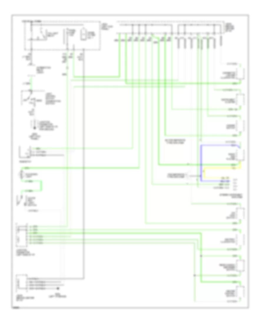
Instrument Illumination Wiring Diagram for Toyota Celica GT 1994
List of elements for Instrument Illumination Wiring Diagram for Toyota Celica GT 1994:
- A13
- A14
- Ashtray illumination
- C13
- C14
- Cigarette lighter illumination
- Ex for separate type amplifier
- F12
- For separate type amplifier
- G200 (left kick panel)
- G202 (left i/p brace)
- Glove box light
- Glove box light switch
- Hazard switch
- Head
- Heater control switch
- Hot at all times
- Ill+
- Ill-
- Instrument cluster
- Integration relay (j/b #1)
- J/b #1 (left kick panel)
- J/b #3 (behind center of i/p)
- Junction connector (left side of i/p)
- Junction connector (left side of i/p) (for ground)
- Light control switch (combination switch)
- Noise filter no. 1
- O/d main switch
- Off
- Panel fuse 7.5a
- Radio and player
- Rear window defogger switch
- Rheostat
- Stereo component amplifier
- Tail
- Taillight relay

 Čeština
 Dansk
Dansk Deutsch
 Ελληνικά
 English
 English
 Español
 Suomi
Suomi Français
 Français
 עברית
עברית Hrvatski
 Magyar
 Italiano
 日本語
日本語 한국어
한국어 Nederlands
 Polski
 Português
 Português
 Română
 Slovenčina
 Slovenščina
 Svenska
 Türkçe
 中文 (中国)