1998 AUDI A6
Audi A6 1998 - BUZZERS, RELAYS & TIMERS
Audi A6 1998 BUZZERS, RELAYS & TIMERS
Component Component Location A/C Clutch Relay On 13-fold relay panel. See Fig. 6. Coolant Fan Control (FC) Relay On 8-fold relay panel. See Fig. 5. Dual Horn Relay On micro central electric panel. See Fig. 3. Foglight Relay On 13-fold relay panel. See Fig. 6. Fuel Pump Relay On micro central electric panel. See Fig. 3. Load Reduction Relay On micro central electric panel. See Fig. 3. Second Speed Coolant Fan Control (FC) Relay On 8-fold relay panel. See Fig. 5. Secondary Air Injection (AIR) Pump Relay On 3-fold relay panel. See Fig. 4. Selector Lever Light Relay On 13-fold relay panel. See Fig. 6. Solar Cell Separation Relay On 13-fold relay panel. See Fig. 6. Starting Interlock Relay On 13-fold relay panel. See Fig. 6. Wiper/Washer Intermittent Relay On micro central electric panel. See Fig. 3.
Audi A6 1998 - CIRCUIT PROTECTION DEVICES
Audi A6 1998 CIRCUIT PROTECTION DEVICES
Component Component Location ABS Control Module Fuse On 8-fold relay panel. See Fig. 5. Control Module Fuse (For Coolant Fan) On 8-fold relay panel. See Fig. 5. Coolant Fan Fuse On 8-fold relay panel. See Fig. 5. Coolant Fan Fuse On 8-fold relay panel. See Fig. 5. Fuse Panel Left side of dash. Micro Central Electric Panel Behind left side of dash. Power Seat Circuit Breaker No. 1 (Driver's Seat) On 8-fold relay panel. See Fig. 5. Power Seat Circuit Breaker No. 2 (Passenger's Seat) On 8-fold relay panel. See Fig. 5. Power Window Circuit Breaker (Front) On 8-fold relay panel. See Fig. 5. Power Window Circuit Breaker (Rear) On 8-fold relay panel. See Fig. 5. Rear Shade Fuse On micro central electric panel. See Fig. 3. Secondary Air Pump Fuse On 13-fold relay panel. See Fig. 6. 3-Fold Relay Panel Left rear of engine compartment, in plenum chamber. 8-Fold Relay Panel Behind left side of dash. 13-Fold Relay Panel Behind left side of dash.
Audi A6 1998 - CONTROL UNITS
Audi A6 1998 CONTROL UNITS
Component Component Location ABS Control Module Integral with ABS hydraulic unit, left side of engine compartment. ABS Hydraulic Unit Left side of engine compartment. Air Bag Control Module Below front of center console. See Fig. 2. Central Locking Control Module Below driver's seat & carpet. See Fig. 2. Cruise Control Module Behind glove box. See Fig. 2. Engine Control Module (ECM) In electronic box, left side of fresh air plenum. See Fig. 1. Fresh Air Blower Control Module Behind right side of dash. See Fig. 2. Headlight Adjustment System Control Module On left side of luggage compartment. See Fig. 2. Light Control Module On 13-fold relay panel. See Fig. 6. Mirror Fold-Away Control Module On 13-fold relay panel. See Fig. 6. Rear Window Shade Control Module On left side of luggage compartment. See Fig. 2. Servotronic Control Module On 13-fold relay panel. See Fig. 6. Throttle Valve Control Module On throttle body. See Fig. 1. Transmission Control Module (TCM) Under right front seat & carpet. See Fig. 2. Ultra-Sound Sensor Control Module Mounted below left "C" pillar. See Fig. 2.
Audi A6 1998 - MOTORS
Audi A6 1998 MOTORS
Component Component Location ABS Return Flow Pump Part of ABS hydraulic unit. Airflow Flap Motor/Position Sensor Near blower motor fresh air intake. Central Air Flap Motor/Position Sensor On right side of evaporative housing. Cruise Control Vacuum Pump Left side of engine compartment. See Fig. 2. Defroster Flap Motor/Position Sensor On right side of evaporative housing. Fresh Air Blower Behind right side of dash. Fuel Pump In fuel tank. Fuel Tank Lid Unlock Motor On right side of luggage compartment. See Fig. 2. Leak Detection Pump (LDP) At back of left rear wheelhousing. Secondary Air Injection (AIR) Pump Motor Right front corner of engine compartment. Temperature Flap Actuator/ Potentiometer (Left) On left side of evaporative housing. Temperature Flap Actuator/ Potentiometer (Right) On right side of evaporative housing.
Audi A6 1998 - SENDING UNITS/SENSORS
Audi A6 1998 SENDING UNITS/SENSORS
Component Component Location ABS Wheel Speed Sensors (4) Mounted at each respective wheel bearing housing. Camshaft Position (CMP) Sensor On front of right cylinder head. See Fig. 1. Camshaft Position (CMP) Sensor No. 2 On rear of left cylinder head. See Fig. 1. Central Flap Motor Position Sensor On right side of evaporator housing. Engine Coolant Temperature (ECT) Sensor On coolant pipe behind intake manifold. See Fig. 1. Engine Coolant Temperature (ECT) Sensor (For Gauge) On coolant pipe behind intake manifold. Engine Oil Temperature Sensor Front left side of engine block. Engine Speed (RPM) Sensor On left side of transmission housing. Fresh Air Intake Duct Temperature Sensor Behind right side of dash. Fuel Level Sensor In fuel tank. Heated Oxygen Sensor (HO2S) No. 1 Right side of engine, in exhaust pipe below manifold. Heated Oxygen Sensor (HO2S) No. 2 Left side of engine, in exhaust pipe below manifold. Intake Air Temperature (IAT) Sensor Mounted in intake air duct at rear of intake manifold. See Fig. 1. Knock Sensor (KS) No. 1 Below intake manifold, near right cylinder head. See Fig. 1. Knock Sensor (KS) No. 2 Below intake manifold, near left cylinder head. See Fig. 1. Mass Airflow (MAF) Sensor On air cleaner assembly. See Fig. 1. Outside Air Temperature Sensor In front of A/C condenser. See Fig. 2. Oxygen Sensor (O2S) Behind three way catalytic converter. Oxygen Sensor (O2S) No. 2 Behind three way catalytic converter. Side Air Bag Crash Sensor (Driver Side) Under driver's seat, on floor pan crossmember. Side Air Bag Crash Sensor (Passenger Side) Under passenger's seat, on floor pan crossmember. Speedometer Vehicle Speed Sensor (VSS) On left side of transmission. See Fig. 2.
Audi A6 1998 - SOLENOIDS/SOLENOID VALVES
Audi A6 1998 SOLENOIDS/SOLENOID VALVES
Component Component Location Evaporative Emission (EVAP) Canister Purge Regulator Valve Right side of engine compartment. See Fig. 1. Intake Manifold Tuning (IMT) Valve At back of intake manifold. See Fig. 1. Secondary Air Injection (AIR) Solenoid Valve At back of intake manifold. See Fig. 1. Shift Lock Solenoid Under center console, part of gear selector mechanism. See Fig. 2. Valve No. 1 (For Camshaft Adjustment) On back of right cylinder head. See Fig. 1. Valve No. 2 (For Camshaft Adjustment) On front of left cylinder head. See Fig. 1.
Audi A6 1998 - SWITCHES
Audi A6 1998 SWITCHES
Component Component Location A/C Pressure Switch On right side of A/C condenser. See Fig. 2. Brake Fluid Level Warning Switch In master cylinder fluid reservoir. Brakelight Switch On brake pedal support bracket. Brake Vacuum Vent Valve Switch On brake pedal support bracket. Coolant Fan Control Thermal Switch On lower right side of radiator. Engine Coolant Level Warning Switch At bottom of coolant reservoir/expansion tank. Hood Alarm Switch Part of hood latch assembly. Kickdown Switch On firewall, part of throttle cable. See Fig. 2. Multifunction Transmission Range (TR) Switch On left side of transmission. See Fig. 2. Oil Pressure Switch On oil filter housing. Parking Brake Warning Light Switch At parking brake lever mechanism. Triptronic Switch Integrated in gear selector cover/trim assembly.
Audi A6 1998 - MISCELLANEOUS
Audi A6 1998 MISCELLANEOUS
Component Component Location Alarm Horn On left side of luggage compartment. Coolant Fan Control (FC) Series Resistance Behind left side of front bumper, on chassis member. See Fig. 2. Data Link Connector (DLC) Below left side of dash. Ignition Coil On front center of engine. See Fig. 1. Ignition Coil No. 2 On front center of engine. See Fig. 1. Ignition Coil No. 3 On front center of engine. See Fig. 1. Power Output Stage On front center of engine. See Fig. 1. Seat Belt Tension Ignitors (2) (Left & Right) At bottom of respective "B" pillar.
Audi A6 1998 - CONNECTORS
Audi A6 1998 CONNECTORS
Component Component Location T6A (Blue, 6 Pin) Above left kick panel. T6B (White, 6 Pin) Above left kick panel. T6E (Gray, 6 Pin) Above right kick panel. T6F (Brown, 6 Pin) Above right kick panel. T6I (Red, 6 Pin) Above right kick panel. T6K (Pink, 6 Pin) Above right kick panel. T6L (Red, 6 Pin) In E-box, at left rear of engine compartment. T6P (Red, 6 Pin) Below left front seat. T6R (Brown, 6 Pin) In luggage compartment. T8C (Black, 8 Pin) In left front door. T10A (Pink, 10 Pin) Above left kick panel. T10B (Red, 10 Pin) Above left kick panel. T10C (Gray, 10 Pin) Above left kick panel. T10E (Violet, 10 Pin) Above left kick panel. T10F (Brown, 10 Pin) Above left kick panel. T10H (Black, 10 Pin) Above left kick panel. T10I (Brown, 10 Pin) Above left kick panel. T10K (Orange, 10 Pin) Above left kick panel. T10N (Yellow, 10 Pin) In E-box, at left rear of engine compartment. T10O (Brown, 10 Pin) In E-box, at left rear of engine compartment. T10P (Black, 10 Pin) In E-box, at left rear of engine compartment. T10T (Orange, 10 Pin) Above right kick panel. T10U (Black, 10 Pin) Above right kick panel. T10V (Brown, 10 Pin) Above right kick panel. T10W (Blue, 10 Pin) Above right kick panel. T10X (Pink, 10 Pin) Above right kick panel. T10Y (Green, 10 Pin) Above right kick panel. T15A (Black, 15 Pin) Above left kick panel. T15D (Black, 15 Pin) Above right kick panel. T15E (White, 15 Pin) In E-box, at left rear of engine compartment.
Audi A6 1998 - GROUNDS
Audi A6 1998 GROUNDS
Component Component Location G12 On left side of engine compartment. G13 On right side of engine compartment. G18 On engine block. G19 On engine block. G22 On ABS hydraulic unit. G43 Near lower right "A" pillar. G44 Near lower left "A" pillar. G75 At right rear pillar.
Audi A6 1998 - COMPONENT LOCATION GRAPHICS
NOTE:
Fig.res may show multiple component locations. - appropriate table for proper figure references.

Fig. 1: Audi A6 1998 - Component Locations - Engine Compartment
Fig. 2: Audi A6 1998 - Component Locations - Vehicle Overview
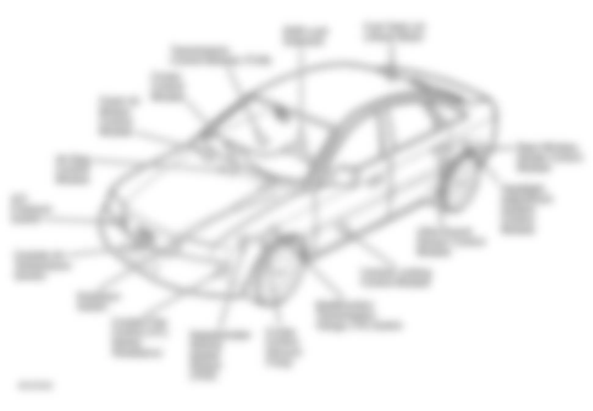
Fig. 3: Audi A6 1998 - Component Locations - Micro Central Electric Panel
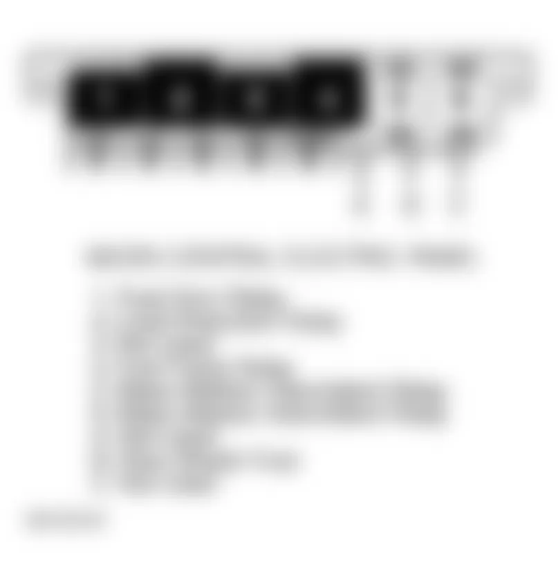
Fig. 4: Audi A6 1998 - Component Locations - 3-Fold Relay Panel
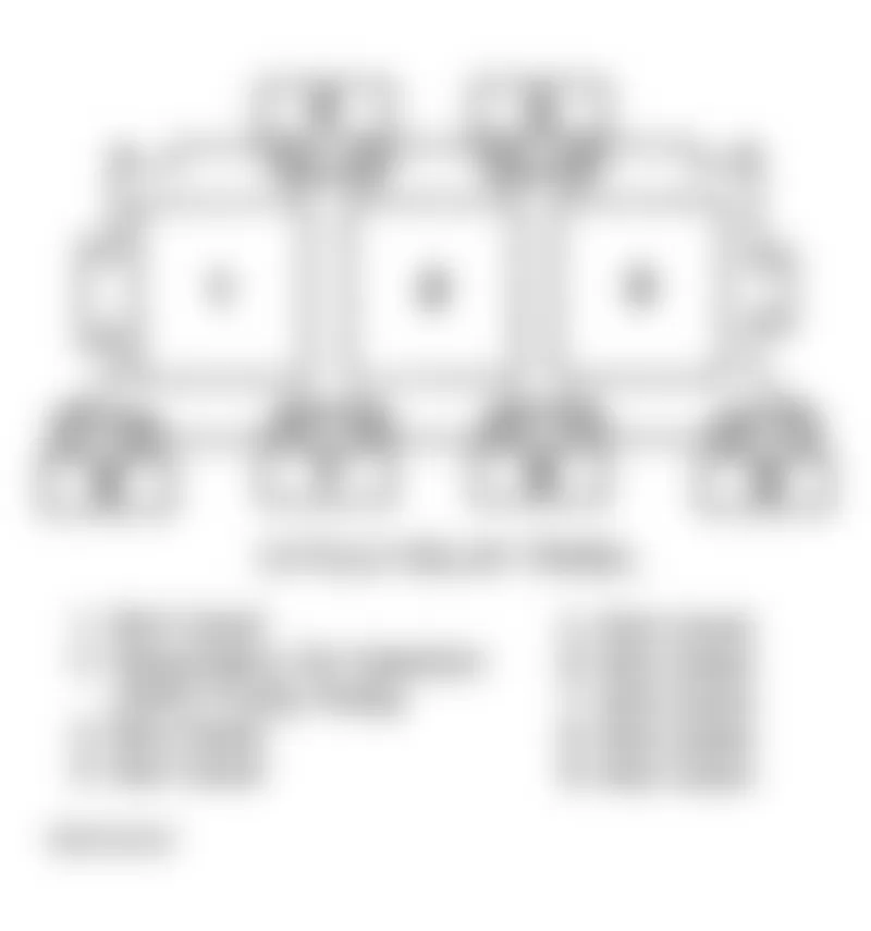
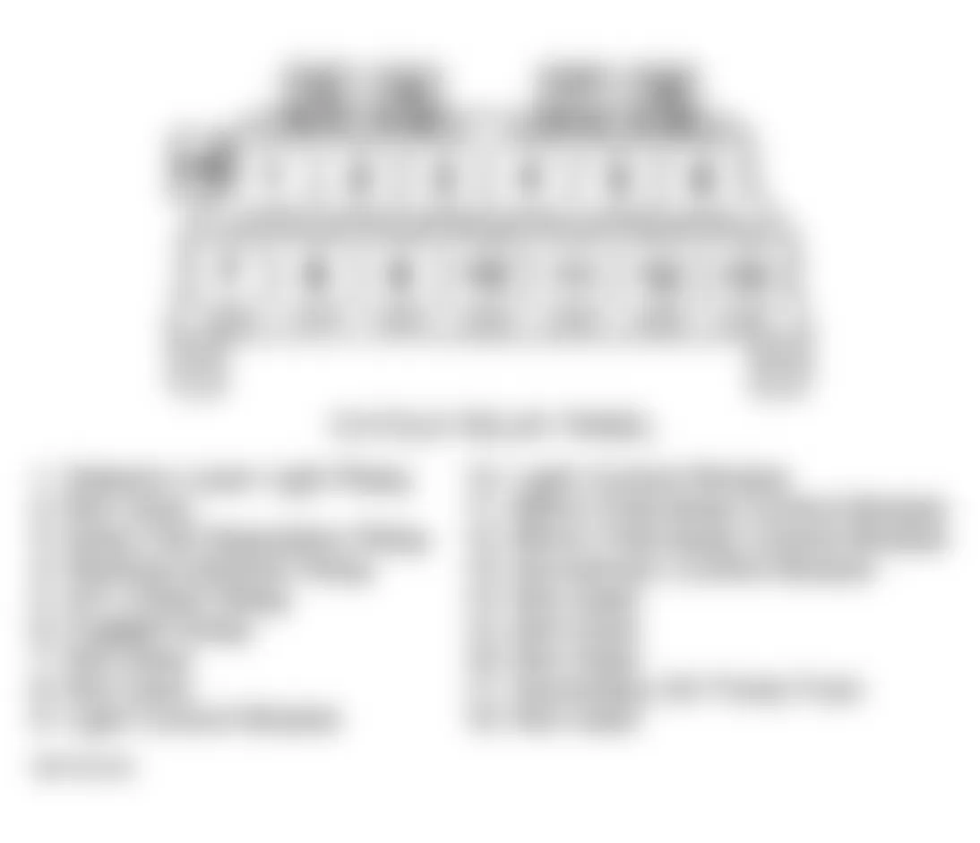
Fig. 5: Audi A6 1998 - Component Locations - 13-Fold Relay Panel
Fig. 6: Audi A6 1998 - Component Locations - 8-Fold Relay Panel