2000 INFINITI G20
Infiniti G20 2000 - BUZZERS, RELAYS & TIMERS
Infiniti G20 2000 BUZZERS, RELAYS & TIMERS
Component Component Location Accessory Relay On fuse block. See Fig. 4 . Air Conditioner Relay In relay box. See Fig. 3 . Blower Relay On fuse block. See Fig. 4 . Combination Flasher Unit Behind left side of dash. See Fig. 4 . Cooling Fan Relay No. 1 In relay box. See Fig. 3 . Cooling Fan Relay No. 2 In relay box. See Fig. 3 . Cooling Fan Relay No. 3 In relay box. See Fig. 3 . Door Mirror Defogger Relay Behind left kick panel. See Fig. 4 . ECM Relay Behind center of dash. See Fig. 4 . Front Foglight Relay In relay box. See Fig. 3 . Fuel Pump Relay No. 1 Behind center of dash. See Fig. 4 . Fuel Pump Relay No. 2 Behind left kick panel. See Fig. 4 . Horn Relay In relay box. See Fig. 3 . Ignition Relay On fuse block. See Fig. 4 . Left Headlamp Relay Behind right kick panel. Multi-Remote Control Relay On fuse block. See Fig. 4 . Park/Neutral Position Relay In relay box. See Fig. 3 . Power Window Relay On fuse block. See Fig. 4 . Rear Window Defogger Relay In relay box. See Fig. 3 . Right Headlamp Relay Behind right kick panel. Taillight Relay Behind right kick panel. Theft Warning Light Relay In relay box. See Fig. 3 . Trunk Lid Opener Relay Behind left side of dash. See Fig. 4 .
Infiniti G20 2000 - CIRCUIT PROTECTION DEVICES
Infiniti G20 2000 CIRCUIT PROTECTION DEVICES
Component Component Location Circuit Breaker No. 1 Behind dash, left of fuse block. See Fig. 4 . Circuit Breaker No. 2 Behind dash, left of fuse block. See Fig. 4 . Fuse Block Behind dash, left of steering column. See Fig. 4 . Fuse & Fusible Link Box Left front of engine compartment, next to battery. See Fig. 1 . Relay Box Right side of engine compartment. See Fig. 1 .
Infiniti G20 2000 - CONTROL UNITS
Infiniti G20 2000 CONTROL UNITS
Component Component Location ABS Actuator & Electric Unit Right front corner of engine compartment. See Fig. 1 . Air Bag Diagnosis Sensor Unit Below rear of center console. See Fig. 4 . ASCD Control Unit Behind dash, left of steering column. See Fig. 4 . A/T Device Under center console, at base of selector lever. Daytime Light Control Unit (Canada) Behind right kick panel. See Fig. 4 . Engine Control Module (ECM) Behind center of dash, at lower left side of glove box. See Fig. 4 . Fan Control Amplifier Behind right side of dash, left of blower motor. Headlamp Battery Saver Control Unit Behind right kick panel. IVCS Unit Under right side of rear package shelf. NATS IMMU On ignition key cylinder. Smart Entrance Control Unit Behind dash, left of steering column. See Fig. 4 . Thermo Control Amplifier Behind right side of dash. Transmission Control Module (TCM) Behind lower center of dash, forward of selector lever. See Fig. 4 .
Infiniti G20 2000 - MOTORS
Infiniti G20 2000 MOTORS
Component Component Location Air Mix Door Motor Behind center of dash, on bottom of heater unit. ASCD Pump Right rear corner of engine compartment, behind strut tower. Blower Motor Below right side of dash. Front Washer Motor At right front of engine compartment, on washer fluid reservoir. Front Wiper Motor Right side of firewall. See Fig. 1 . Fuel Pump In fuel tank. Intake Door Motor Behind right side of dash, on left side of air intake unit. Mode Door Motor Behind dash, on left end of heater unit. Sun Roof Motor At front of sun roof opening.
Infiniti G20 2000 - SENDING UNITS & SENSORS
Infiniti G20 2000 SENDING UNITS & SENSORS
Component Component Location ABS Wheel Sensors (4) On each wheel hub assembly. Absolute Pressure Sensor Center of firewall. See Fig. 2 . Ambient Sensor On left front of A/C condenser. Camshaft Position Sensor In distributor. Crankshaft Position Sensor (OBD) On transaxle housing, facing flywheel teeth. See Fig. 2 . EGR Temperature Sensor On top right rear of engine. Engine Coolant Temperature Sensor On lower front of intake manifold. See Fig. 2 . EVAP Control System Pressure Sensor On left rear underside of vehicle. Fuel Level Sensor Unit Top of fuel tank. Heated Oxygen Sensor (Front) On exhaust manifold. See Fig. 2 . Heated Oxygen Sensor (Rear) On exhaust system, rear of catalytic converter. Intake Air Temperature Sensor At left front corner of engine compartment, on air duct housing. See Fig. 2 . Intake Sensor In A/C cooling unit, on evaporator core. In-Vehicle Sensor On dash lower panel, right of steering column. Knock Sensor On right side of cylinder block, below intake manifold. Mass Airflow Sensor On air intake assembly, next to air cleaner box. See Fig. 2 . PTC Integral to A/C push control unit. Refrigerant Pressure Sensor At left front of engine compartment, on A/C liquid tank. Revolution Sensor (A/T) On right rear side of transaxle. Satellite Sensor (Left/Right) At base of respective "B" pillar. Sunload Sensor On right defroster grille. Throttle Position Sensor On throttle body assembly. See Fig. 2 . Vehicle Speed Sensor On top right side of transaxle.
Infiniti G20 2000 - SOLENOIDS & SOLENOID VALVES
Infiniti G20 2000 SOLENOIDS & SOLENOID VALVES
Component Component Location EGR Volume Control Valve On top center rear of engine. See Fig. 2 . EVAP Canister Purge Volume Control Solenoid Valve On top right front of engine. See Fig. 2 . EVAP Canister Vent Control Valve On left rear underside of vehicle. Fuel Injector (4) On top of engine. See Fig. 2 . IACV-AAC Valve On rear of engine, below throttle body. See Fig. 2 . Shift Lock Solenoid (A/T) Under center console, integral to A/T device. Vacuum Cut Valve By-Pass Valve On left rear underside of vehicle.
Infiniti G20 2000 - SWITCHES
Infiniti G20 2000 SWITCHES
Component Component Location ASCD Brake Switch On bracket, above brake pedal. ASCD Clutch Switch (M/T) On bracket, above clutch pedal. Back-Up Light Switch (M/T) On rear of transaxle. Brake Fluid Level Switch In brake fluid reservoir. Clutch Interlock Switch (M/T) On bracket, above clutch pedal. Hood Switch (Anti-Theft System) At left side of engine compartment. See Fig. 1 . Oil Pressure Switch On right front side of cylinder block. Park/Neutral Position Switch (A/T) On left rear side of transaxle. Park/Neutral Position Switch (M/T) On right front of transaxle. Park Position Switch (A/T) Under center console, integral to A/T device. Parking Brake Switch On base of park brake lever. Power Steering Oil Pressure Switch On right rear corner of engine compartment, on power steering high pressure tube. See Fig. 2 . Seat Belt Buckle Switch In driver's seat belt buckle. Stoplight Switch On bracket, above brake pedal. Thermal Transmitter On lower front of intake manifold. Throttle Position Switch On throttle body assembly. See Fig. 2 . Washer Level Switch At right front of engine compartment, on washer fluid reservoir.
Infiniti G20 2000 - MISCELLANEOUS
Infiniti G20 2000 MISCELLANEOUS
Component Component Location Data Link Connector (DLC) Under left dash panel, near fuse box cover. Diode (Anti-Theft System) Behind left side of dash, taped to harness. Diode (Joint Connector No. 3) (TCM) Behind center of dash, taped to harness. Diode (Joint Connector No. 4) (Combination Switch) Behind center of dash, taped to harness. Diode (Parking Brake Switch) Behind center of dash, taped to harness. Diode (Rear Window Defogger Relay) Behind center of dash, taped to harness. Diode (Trunk Light) Behind right side of dash, taped to harness. Distributor On rear of engine. See Fig. 2 . Dropping Resistor (A/T) On left front of engine compartment. Fan Resistor Behind right side of dash, near blower motor. Ignition Coil In distributor. Joint Connector No. 1 Behind right side of dash, taped to harness. Joint Connector No. 2 Behind right side of dash, taped to harness. Joint Connector No. 4 Behind center of dash, taped to harness. Power Transistor In distributor.
Infiniti G20 2000 - CONNECTORS
Infiniti G20 2000 CONNECTORS
Component Component Location B2 (White, 12-Pin) Behind left side of dash. B3 (White, 20-Pin) Behind left side of dash. B9 (White, 8-Pin) At left "B" pillar. B10 (Green, 12-Pin) Above left rear wheelwell. B18 (White, 8-Pin) Under center console. B27 (White, 8-Pin) At right "B" pillar. B28 (White, 12-Pin) Behind left side of dash. B29 (White, 8-Pin) Behind left side of dash. B51 (White, 8-Pin) Under center console. B101 (White, 2-Pin) At right kick panel. B102 (Green, 10-Pin) At right kick panel. B103 (White, 20-Pin) At right kick panel. B104 (White, 8-Pin) At right kick panel. B113 (White, 18-Pin) At right rear quarterpanel. B120 (Green, 12-Pin) At base of left "C" pillar. B121 (White, 6-Pin) At right rear quarterpanel. D1 (White, 18-Pin) At left end of dash. D2 (White, 8-Pin) At left end of dash. D21 (White, 18-Pin) At right end of dash. D41 (White, 8-Pin) At left "B" pillar. D61 (White, 8-Pin) At right "B" pillar. E33 (Gray, 9-Pin) At right front of engine compartment. E34 (Gray, 1-Pin) At right front of engine compartment. E35 (Gray, 1-Pin) At right side of engine compartment. E36 (Gray, 8-Pin) At right side of engine compartment. E57 (Gray, 6-Pin) At right side of engine compartment. E75 Behind left side of dash. E84 (White, 8-Pin) Behind right kick panel. E101 (Gray, 9-Pin) At right front of engine compartment. E102 (Gray, 1-Pin) At right front of engine compartment. E103 (Gray, 1-Pin) At right front of engine compartment. E104 (Gray, 8-Pin) At right front of engine compartment. E123 (Green, 8-Pin) On right side of engine. E128 (Blue, 8-Pin) At top of transmission. E130 (Gray, 6-Pin) At right side of engine compartment. F6 (Green, 8-Pin) At right top of engine. F13 (Gray, 10-Pin) At right front of engine. F23 (White, 18-Pin) Under front of center console. F24 (White, 20-Pin) Under front of center console. F25 (White, 16-Pin) Under front of center console. F27 (Blue, 8-Pin) At rear of engine. F31 (White, 6-Pin) Under front of center console. F51 (Gray, 10-Pin) At right front of engine. M6 Behind left side of dash. M7 (White, 12-Pin) Behind left side of dash. M8 (White, 20-Pin) Behind left side of dash. M16 (White, 18-Pin) Behind left end of dash. M17 (White, 8-Pin) Behind left end of dash. M46 (White, 20-Pin) Under front of center console. M49 (White, 18-Pin) Under front of center console. M62 (White, 20-Pin) Under front of center console. M63 (White, 16-Pin) Under front of center console. M70 (White, 6-Pin) At base of right "A" pillar. M72 (White, 18-Pin) Behind right side of dash. M73 (White, 2-Pin) Behind right side of dash. M74 (Green, 10-Pin) Behind right side of dash. M75 (White, 20-Pin) Behind right side of dash. M89 (White, 20-Pin) Behind upper left side of dash. M90 (White, 12-Pin) Behind right end of dash. M91 (White, 8-Pin) Behind right end of dash. M95 (White, 6-Pin) Behind upper center of dash. R1 (White, 6-Pin) At base of right "A" pillar. R8 (White, 12-Pin) At base of left "A" pillar. T1 (White, 18-Pin) At right front of luggage compartment. T19 (Gray, 8-Pin) At left rear of luggage compartment. T20 (Gray, 8-Pin) At left rear of luggage compartment. T31 (White, 6-Pin) At right front of luggage compartment. T32 (White, 6-Pin) In trunk lid. T51 (White, 6-Pin) At right rear of trunk lid. Z3 (White, 20-Pin) Behind center of dash.
Infiniti G20 2000 - GROUNDS
Infiniti G20 2000 GROUNDS
Component Component Location B6 At base of left "B" pillar. B7 At base of left "B" pillar. B24 At base of right "B" pillar. B25 At base of right "B" pillar. B56 Behind right headlight. B72 Under left "C" pillar trim. B109 Under right rear seat back trim. B110 Under right rear seat back trim. E9 Near hood switch. E9 At front of left strut tower. See Fig. 2 . E28 At front of right inner fender panel. See Fig. 2 . E56 At front of right inner fender panel. See Fig. 2 . E105 Near alternator. E109 At left front of cylinder head cover. See Fig. 2 . F15 Near throttle valve assembly. See Fig. 2 . F16 Near throttle valve assembly. See Fig. 2 . M15 At left kick panel. See Fig. 4 . M71 Behind right end of dash. See Fig. 4 . M76 At right kick panel. See Fig. 4 .
Infiniti G20 2000 - COMPONENT LOCATION GRAPHICS
NOTE:
Fig.res may show multiple component locations. - appropriate table for proper figure references.
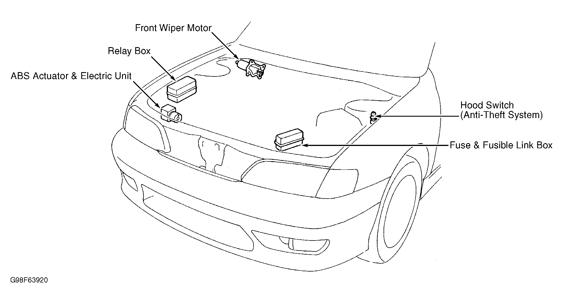
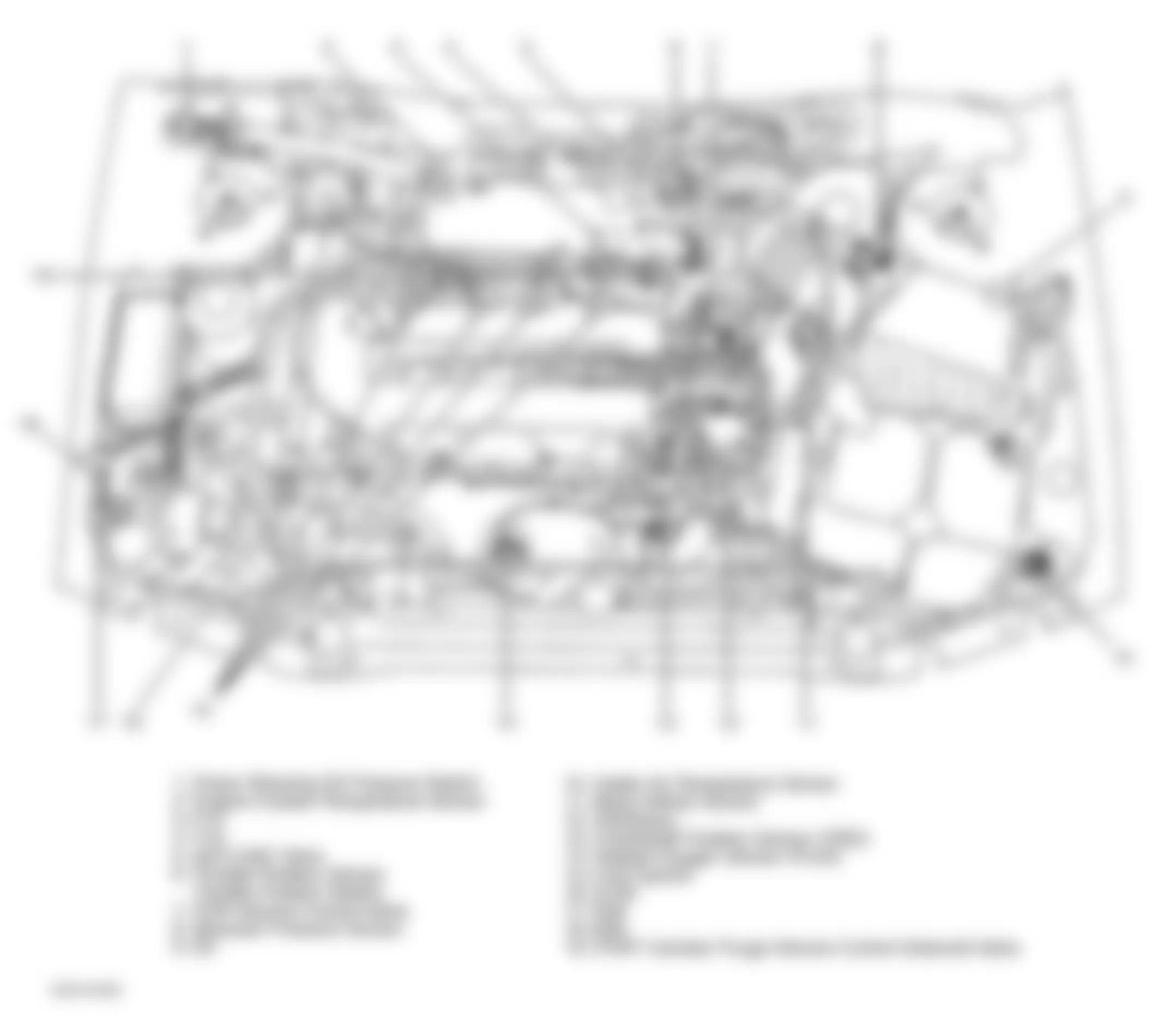
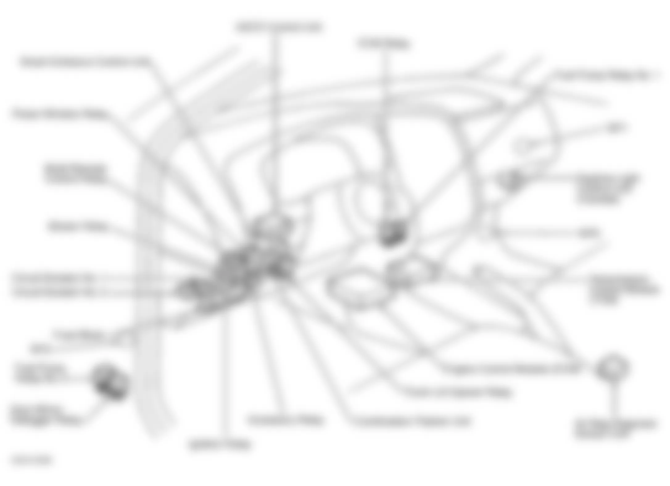
Fig. 1: Infiniti G20 2000 - Component Locations - Engine Compartment
Fig. 2: Infiniti G20 2000 - Component Locations - Engine Compartment