2004 INFINITI I35
Infiniti I35 2004 - BUZZERS, RELAYS & TIMERS
Infiniti I35 2004 BUZZERS, RELAYS & TIMERS LOCATION
Component Location Accessory Relay In fuse block (J/B). See Fig. 1 . Air Conditioner Relay In relay box-1. See Fig. 2 . Blower Motor Relay In fuse block (J/B). See Fig. 1 . Blower Motor Relay Behind right side of dash. See Fig. 4 . Combination Flasher Unit Behind left side of dash. See Fig. 3 . Cooling Fan Relay-1 In relay box-2. See Fig. 2 . Cooling Fan Relay-2 In relay box-2. See Fig. 2 . Cooling Fan Relay-3 In relay box-2. See Fig. 2 . Cornering Lamp Relay In relay box-1. See Fig. 2 . Door Mirror Defogger Relay In relay box-1. See Fig. 2 . ECM Relay In relay box-2. See Fig. 2 . Front Fog Lamp Relay In relay box-1. See Fig. 2 . Fuel Pump Relay Behind left kick panel. See Fig. 4 . Headlamp Relay (Left) In relay box-1. See Fig. 2 . Headlamp Relay (Right) In relay box-1. See Fig. 2 . Heated Steering Relay (M231) Behind right side of dash, behind A/C fan control unit. See Fig. 6 . Horn Relay In relay box-1. See Fig. 2 . Ignition Relay In fuse block (J/B). See Fig. 1 . Park/Neutral Position Relay In relay box-2. See Fig. 2 . Power Window Relay Behind left side of dash, left of fuse block (J/B). See Fig. 3 . Rear Window Defogger Relay Behind left kick panel. See Fig. 4 . Tail Lamp Relay In relay box-1. See Fig. 2 . Throttle Control Motor Relay In relay box-2. See Fig. 2 . Vehicle Security Horn Relay-1 In relay box-1. See Fig. 2 . Vehicle Security Horn Relay-2 In relay box-1. See Fig. 2 .
Infiniti I35 2004 - CIRCUIT PROTECTION DEVICES
Infiniti I35 2004 CIRCUIT PROTECTION DEVICES LOCATION
Component Location Circuit Breaker Behind left side of dash, near fuse block (J/B). See Fig. 4 . Fuse Block (J/B) Behind left side of dash. See Fig. 3 . Fuse & Fusible Link Box At left side of engine compartment. See Fig. 2 . Relay Box-1 At right side of engine compartment. See Fig. 2 . Relay Box-2 At left front corner of engine compartment. See Fig. 2 . VDC Relay Box (E165, E166) At left rear of engine compartment, near ABS actuator & electrical unit. See Fig. 7 .
Infiniti I35 2004 - CONTROL UNITS
Infiniti I35 2004 CONTROL UNITS LOCATION
Component Location ABS Actuator (E168, E169) At left rear of engine compartment, near brake master cylinder. See Fig. 7 . ABS/TCS Control Unit At left rear corner of engine compartment. See Fig. 2 . A/C Auto Amplifier Behind center of dash. See Fig. 3 . Air Bag Diagnosis Sensor Unit Under rear of center console. See Fig. 4 . Audio Unit Behind center of dash. See Fig. 3 . Daytime Light Control Unit (Canada) At right front corner of engine compartment. See Fig. 2 . ECM Behind instrument lower cover. See Fig. 4 . Front Monitor Upper center of dash. See Fig. 3 . Heater Unit Behind instrument lower cover. See Fig. 4 . IVIS IMMU On ignition key cylinder. See Fig. 4 . Left Seat Control Unit Under driver seat. See Fig. 4 . NAVI Control Unit Behind center of dash. See Fig. 3 . Passenger Air Bag Module (149) Right side of dash. See Fig. 6 . Shift Lock Control Unit Below center console. See Fig. 4 . Smart Entrance Control Unit Behind lower center of dash. See Fig. 4 . Transmission Control Module (TCM) Behind lower center of dash. See Fig. 4 . VDC/TCS/ABS Control Unit Under driver seat. See Fig. 4 .
Infiniti I35 2004 - MOTORS
Infiniti I35 2004 MOTORS LOCATION
Component Location Air Mix Door Motor (M51) Behind center of dash. See Fig. 6 . Blower Motor Behind right side of dash. See Fig. 8 . Cooling Fan Motor-1 (E38) Behind left side of radiator. See Fig. 7 . Cooling Fan Motor-2 (E43) Behind right side of radiator. See Fig. 7 . Electric Throttle Control Actuator (F63) On throttle body. See Fig. 9 . Front Door Lock Actuator (Left) Rear of left front door. See Fig. 14 . Front Power Lock Actuator (Right) Rear of right front door. See Fig. 15 . Front Power Window Motor (Left) Front of left front door. See Fig. 14 . Front Power Window Motor (Right) Front of right front door. See Fig. 15 . Front Washer Motor (E41) In washer reservoir. See Fig. 7 . Front Wiper Motor On right side of firewall. See Fig. 2 . Fuel Level Sensor Unit & Fuel Pump (B19) In fuel tank. See Fig. 10 . Fuel Lid Opener Actuator At left rear side of vehicle. See Fig. 5 . Intake Door Motor (M84) Behind right side of dash. See Fig. 6 . Mode Door Motor (M49) Behind center of dash. See Fig. 6 . Rear Door Lock Actuator (Left) Rear of left rear door. See Fig. 16 . Rear Door Lock Actuator (Right) Rear of right rear door. See Fig. 17 . Rear Power Window Motor (Left) Front of left rear door. See Fig. 16 . Rear Power Window Motor (Right) Front of right rear door. See Fig. 17 . Rear Sunshade Unit Under rear parcel shelf. See Fig. 5 . Starter Motor (E201, E202) Left side of engine. See Fig. 7 . Sun Roof Motor At center front of roof. See Fig. 13 . Trunk Lid Opener Actuator At center rear of trunk. See Fig. 12 .
Infiniti I35 2004 - SENDING UNITS & SENSORS
Infiniti I35 2004 SENDING UNITS & SENSORS LOCATION
Component Location Accelerator Pedal Position Sensor (M215) On accelerator pedal bracket. See Fig. 6 . Ambient Sensor (E55) Near right front corner of vehicle. See Fig. 7 . Auto Light Sensor (M202) On left defroster grille. See Fig. 6 . Camshaft Position Sensor (PHASE) (Bank 1) (F212) At right rear of engine. See Fig. 9 . Camshaft Position Sensor (PHASE) (Bank 2) (F64) At left rear of engine. See Fig. 9 . Crankshaft Position Sensor (POS) (F173) On front of oil pan, below crankshaft pulley. See Fig. 9 . Crash Zone Sensor (E148) At front center of engine compartment. See Fig. 7 . Engine Coolant Temperature Sensor (F22) On top left rear of engine. See Fig. 9 . EVAP Control System Pressure Sensor (B23) Under vehicle, near EVAP canister. See Fig. 10 . Front Wheel Sensor (Left) (W/ TCS) (E163) On left front steering knuckle assembly. See Fig. 7 . Front Wheel Sensor (Left) (W/ VDC) (E167) On left front steering knuckle assembly. See Fig. 7 . Front Wheel Sensor (Right) (W/ TCS) (E164) On right front steering knuckle assembly. See Fig. 7 . Front Wheel Sensor (Right) (W/ VDC) (E160) On right front steering knuckle assembly. See Fig. 7 . Fuel Level Sensor Unit & Fuel Pump (B19) In fuel tank. See Fig. 10 . Heated Oxygen Sensor 1 (Bank 1) (F59) On right front exhaust tube assembly. See Fig. 9 . Heated Oxygen Sensor 1 (Bank 2) (F60) On left front exhaust tube assembly. See Fig. 9 . Heated Oxygen Sensor 2 (Bank 1) (F61) On exhaust system, after three-way catalyst. See Fig. 9 . Heated Oxygen Sensor 2 (Bank 2) (F68) On three-way catalyst manifold. See Fig. 9 . Intake Sensor (M80) Behind right side of dash. See Fig. 6 . In-Vehicle Sensor (M44) Behind left center of dash. See Fig. 6 . Knock Sensor (F132) On top of cylinder block. See Fig. 9 . Mass Air Flow Sensor (F15) On intake air duct. See Fig. 9 . Power Steering Pressure Sensor (F55) On power steering high pressure tube. See Fig. 9 . Power Train Revolution Sensor (F115) On right rear side of transaxle. See Fig. 9 . Rear Wheel Sensor (Left) (W/ TCS) (B73) On left rear wheel hub assembly. See Fig. 10 . Rear Wheel Sensor (Left) (W/ VDC) (B77) On left rear wheel hub assembly. See Fig. 10 . Rear Wheel Sensor (Right) (W/ TCS) (B72) On right rear wheel hub assembly. See Fig. 10 . Rear Wheel Sensor (Right) (W/ VDC) (B76) On right rear wheel hub assembly. See Fig. 10 . Refrigerant Pressure Sensor (E37) On A/C liquid tank. See Fig. 7 . Revolution Sensor (F112) On top right rear of transaxle. See Fig. 9 . Satellite Sensor (Left) (B36) At base of left "B" pillar. See Fig. 10 . Satellite Sensor (Right) (B131) At base of right "B" pillar. See Fig. 11 . Steering Angle Sensor (M218) On steering column, near spiral cable assembly. See Fig. 6 . Sunload Sensor (M85) On right defroster grille. See Fig. 6 . Vehicle Speed Sensor (W/ VDC) (F113) At top right rear of transaxle. See Fig. 9 . Yaw Rate/Side G Sensor (B60) Under center console, forward of shift selector lever. See Fig. 10 .
Infiniti I35 2004 - SOLENOIDS & SOLENOID VALVES
Infiniti I35 2004 SOLENOIDS & SOLENOID VALVES LOCATION
Component Location EVAP Canister Purge Volume Control Solenoid Valve (F199) On right side of intake manifold collector. See Fig. 9 . EVAP Canister Vent Control Valve (B22) On EVAP canister. See Fig. 10 . Ignition Coil No. 1 (F222) Top rear of engine. See Fig. 9 . Ignition Coil No. 2 (F35) Top front of engine. See Fig. 9 . Ignition Coil No. 3 (F223) Top rear of engine. See Fig. 9 . Ignition Coil No. 4 (F31) Top front of engine. See Fig. 9 . Ignition Coil No. 5 (F224) Top rear of engine. See Fig. 9 . Ignition Coil No. 6 (F30) Top front of engine. See Fig. 9 . Injector No. 1 (F192) Top rear of engine. See Fig. 9 . Injector No. 2 (F37) Top front of engine. See Fig. 9 . Injector No. 3 (F193) Top rear of engine. See Fig. 9 . Injector No. 4 (F36) Top front of engine. See Fig. 9 . Injector No. 5 (F194) Top rear of engine. See Fig. 9 . Injector No. 6 (F28) Top front of engine. See Fig. 9 . Intake Valve Timing Control Solenoid Valve (Bank 1) (F200) On right front of engine. See Fig. 9 . Intake Valve Timing Control Solenoid Valve (Bank 2) (F62) On left front of engine. See Fig. 9 . Key Lock Solenoid On ignition key cylinder. Line Pressure Solenoid Valve On control valve upper body, in transaxle. Overrun Clutch Solenoid Valve On control valve upper body, in transaxle. Shift Lock Solenoid Integral to A/T device. Shift Solenoid Valve A On control valve upper body, in transaxle. Shift Solenoid Valve B On control valve upper body, in transaxle. Torque Converter Clutch Solenoid Valve On control valve lower body, in transaxle. Vacuum Cut Valve By-Pass Valve (B21) On EVAP purge line, between fuel tank & EVAP canister. See Fig. 10 . VIAS Control Solenoid Valve (F29) On top right front of engine, on intake manifold collector. See Fig. 9 .
Infiniti I35 2004 - SWITCHES
Infiniti I35 2004 SWITCHES LOCATION
Component Location ASCD Brake Switch On brake pedal bracket. See Fig. 8 . Brake Fluid Level Switch (E1) On master cylinder reservoir. See Fig. 7 . Hood Switch At left front corner of engine compartment. See Fig. 2 . Left Seat Belt Buckle Switch (B34) In driver seat belt buckle. See Fig. 10 . Oil Pressure Switch (F198) On right front side of oil pan, near oil filter. See Fig. 9 . Parking Brake Switch At base of parking brake lever assembly. See Fig. 8 . Park/Neutral Position Switch (F94) On left rear side of transaxle. See Fig. 9 . Right Seat Belt Buckle Switch (B145) In passenger seat belt buckle. See Fig. 11 . Stop Lamp Switch On brake pedal bracket. See Fig. 8 . Washer Level Switch (E42) In washer reservoir. See Fig. 7 .
Infiniti I35 2004 - MISCELLANEOUS
Infiniti I35 2004 MISCELLANEOUS LOCATION
Component Location Alternator (A2, E46, E47) Right front of engine. See Fig. 7 . Antenna Amplifier At right "C" pillar. See Fig. 5 . A/T Device (M233) Under center console. See Fig. 6 . BOSE Speaker Amplifier Under rear parcel shelf. See Fig. 5 . Compressor (A3) Right front of engine. See Fig. 7 . Condenser (B27) Left side of rear compartment. See Fig. 10 . Condenser (F34) Near top front of engine. See Fig. 9 . Condenser (Rear Window Defogger) (B54) At left "C" pillar. See Fig. 10 . Data Link Connector Lower left side of dash. See Fig. 3 . Diode (E79) Left end of dash. See Fig. 8 . Diode (E146) Upper left side of dash). See Fig. 8 . Diode (M13) Upper left end of dash. See Fig. 6 . Diode (M29) Upper left side of dash. See Fig. 6 . Diode (M35) Upper left side of dash. See Fig. 6 . Dropping Resistor (E16) At left rear side of engine compartment, near air cleaner box. See Fig. 7 . Fan Control Amplifier (M31) Behind right side of dash, on blower & cooling unit. See Fig. 6 . Front Electronic Controlled Engine Mount (F23) On lower left rear of engine. See Fig. 9 . Horn (High) Front of radiator. See Fig. 7 . Joint Connector-7 (E18) In fuse & fusible link box. See Fig. 7 . Joint Connector-8 (E19) In fuse & fusible link box. See Fig. 7 . Joint Connector-9 (E20) In fuse & fusible link box. See Fig. 7 . Joint Connector-10 (E21) In fuse & fusible link box. See Fig. 7 . Joint Connector-12 (E73) In relay box-1. See Fig. 7 . Joint Connector-13 (E74) In relay box-1. See Fig. 7 . Joint Connector-14 (E75) In relay box-1. See Fig. 7 . Joint Connector-18 (F46) Lower left side of dash, near ECM. See Fig. 9 . Joint Connector-20 (E71) Lower left side of dash, near ECM. See Fig. 9 . Rear Electronic Controlled Engine Mount (F9) On lower right rear of engine. See Fig. 9 . Rear Window Defogger (B61) Right "C" pillar. See Fig. 10 . SMJ Behind left side of dash. See Fig. 3 . Terminal Cord Assembly (F92) Left front side of engine compartment. See Fig. 9 . Vehicle Security Horn At front center of engine compartment. See Fig. 2 .
Infiniti I35 2004 - CONNECTORS
Infiniti I35 2004 CONNECTORS LOCATION
Component Location A1 (Gray, 3 Pin) At right front of engine compartment. See Fig. 7 . B1 (White, 16 Pin) Behind left side of dash. See Fig. 10 . B2 (Brown, 24 Pin) Behind left side of dash. See Fig. 10 . B3 (White, 18 Pin) Behind left side of dash. See Fig. 10 . B17 (White, 10 Pin) At left rear of luggage compartment. See Fig. 10 . B24 (White, 16 Pin) At left rear of luggage compartment. See Fig. 10 . B25 (White, 20 Pin) At left rear of luggage compartment. See Fig. 10 . B31 (White, 10 Pin) At left "B" pillar. See Fig. 10 . B43 (White, 16 Pin) Under left front seat. See Fig. 10 . B55 (Black, 2 Pin) Behind left side of dash. See Fig. 10 . B56 (White, 18 Pin) Behind left side of dash. See Fig. 10 . B58 (White, 20 Pin) Under left front seat. See Fig. 10 . B59 (White, 16 Pin) Under left front seat. See Fig. 10 . B71 (White, 18 Pin) At left "B" pillar. See Fig. 10 . B103 (White, 12 Pin) Behind right side of dash. See Fig. 11 . B104 (White, 10 Pin) Behind right side of dash. See Fig. 11 . B109 (Brown, 2 Pin) At rear of trunk lid. See Fig. 11 . B119 (White, 16 Pin) Behind left taillight assembly. See Fig. 11 . B120 (White, 20 Pin) Behind left taillight assembly. See Fig. 11 . B130 (White, 10 Pin) At right "B" pillar. See Fig. 11 . B144 (Brown, 24 Pin) Behind right side of dash. See Fig. 11 . B146 (White, 18 Pin) At right "B" pillar. See Fig. 11 . B148 (White, 20 Pin) Right end of dash. See Fig. 11 . B149 (White, 16 Pin) Right side of rear compartment. See Fig. 11 . B150 (White, 16 Pin) Right side of rear compartment. See Fig. 11 . B161 (Brown, 2 Pin) At rear of trunk lid. See Fig. 11 . B170 (White, 16 Pin) Right side of rear compartment. See Fig. 11 . B171 (White, 16 Pin) Right side of rear compartment. See Fig. 11 . D1 (SMJ) At left kick panel. See Fig. 14 . D31 (SMJ) At right kick panel. See Fig. 15 . D61 (SMJ Right end of dash. See Fig. 15 . D62 (White, 16 Pin) Right end of dash. See Fig. 15 . D63 (White, 10 Pin) Right end of dash. See Fig. 15 . D81 (White, 10 Pin) At left "B" pillar. See Fig. 16 . D87 (White, 18 Pin) At left "B" pillar. See Fig. 16 . D101 (White, 10 Pin) At right "B" pillar. See Fig. 17 . D107 (White, 18 Pin) At right "B" pillar. See Fig. 17 . E8 (Gray, 8 Pin) At left rear of engine compartment. See Fig. 7 . E13 (Gray, 1 Pin) At left side of engine compartment. See Fig. 7 . E15 (Black, 8 Pin) In front of left strut tower. See Fig. 7 . E51 (Gray, 3 Pin) At middle front of engine compartment. See Fig. 7 . E81 (SMJ) Behind lower left side of dash. See Fig. 8 . E105 (Green, 2 Pin) At right kick panel. See Fig. 8 . E147 (Yellow, 4 Pin) At right kick panel. See Fig. 8 . E150 (White, 18 Pin) Behind lower left side of dash. See Fig. 8 . E151 (Black, 2 Pin) Behind lower left side of dash. See Fig. 8 . E152 (White, 8 Pin) Behind lower left side of dash. See Fig. 8 . E200 (Gray, 1 Pin) At left side of engine compartment. See Fig. 7 . F8 (Black, 2 Pin) At left rear of engine. See Fig. 9 . F10 (Gray, 10 Pin) At top of transmission. See Fig. 9 . F14 (Brown, 8 Pin) At top rear of transmission. See Fig. 9 . F17 (Gray, 8 Pin) At left side of engine compartment. See Fig. 9 . F18 (Black, 8 Pin) At left side of engine compartment. See Fig. 9 . F25 (Green, 4 Pin) At left rear of engine. See Fig. 9 . F49 (White, 20 Pin) At right front of engine compartment. See Fig. 9 . F53 (White, 18 Pin) At right front of engine compartment. See Fig. 9 . F56 (Green, 8 Pin) At front of engine. See Fig. 9 . F57 (Green, 6 Pin) At right front of engine. See Fig. 9 . F58 (Blue, 4 Pin) At right rear of engine. See Fig. 9 . F65 (Gray, 8 Pin) At rear of engine. See Fig. 9 . F66 (White, 18 Pin) At right front of engine compartment. See Fig. 9 . F67 (White, 20 Pin) At right front of engine compartment. See Fig. 9 . F91 (Brown, 8 Pin) At top of transmission. See Fig. 9 . F93 (Gray, 10 Pin) Left front of engine compartment. See Fig. 9 . F114 (Gray, 8 Pin) At top of transmission. See Fig. 9 . F131 (Black, 2 Pin) At rear of engine. See Fig. 9 . F171 (Green, 4 Pin) At left side of engine. See Fig. 9 . F197 (Green, 8 Pin) At left front of engine. See Fig. 9 . F211 (Blue, 4 Pin) At right rear of engine. See Fig. 9 . F221 (Green, 6 Pin) At rear of engine. See Fig. 9 . M2 (Brown, 24 Pin) Behind lower left side of dash. See Fig. 6 . M4 (SMJ) Behind lower left side of dash. See Fig. 6 . M5 (White, 16 Pin) Behind left side of dash. See Fig. 6 . M6 (White, 18 Pin) Behind left side of dash. See Fig. 6 . M8 (White, 12 Pin) Behind upper left side of dash. See Fig. 6 . M15 (SMJ) Behind left side of dash. See Fig. 6 . M30 (White, 4 Pin) Behind center of dash. See Fig. 6 . M38 (White, 16 Pin) Behind right end of dash. See Fig. 6 . M39 (White, 10 Pin) Behind right end of dash. See Fig. 6 . M81 (White, 20 Pin) Behind center of dash. See Fig. 6 . M91 (White, 12 Pin) Behind center of dash. See Fig. 6 . M92 (White, 10 Pin) Behind glove box. See Fig. 6 . M97 (Green, 2 Pin) Behind glove box. See Fig. 6 . M104 (Brown, 24 Pin) Behind center of dash. See Fig. 6 . M110 (White, 16 Pin) Under center console. See Fig. 6 . M147 (White, 3 Pin) Behind instrument cluster. See Fig. 6 . M150 (Yellow, 4 Pin) At right "A" pillar. See Fig. 6 . M151 (White, 4 Pin) Behind upper center of dash. See Fig. 6 . M191 (Brown, 24 Pin) Behind upper center of dash. See Fig. 6 . M201 (White, 3 Pin) Behind upper left side of dash. See Fig. 6 . M210 (White, 8 Pin) Behind lower left side of dash. See Fig. 6 . M223 (White, 18 Pin) At center bottom of dash. See Fig. 6 . M226 (White, 16 Pin) Under center console. See Fig. 6 . M227 (White, 20 Pin) Under center console. See Fig. 6 . M228 (Brown, 24 Pin) At right end of dash. See Fig. 6 . M229 (White, 18 Pin) At center bottom of dash. See Fig. 6 . M230 (White, 20 Pin) At center bottom of dash. See Fig. 6 . M234 (White, 20 Pin) Upper right side of dash. See Fig. 6 . R2 (White, 12 Pin) Behind left side of dash. See Fig. 13 . T3 (White, 10 Pin) At left side of luggage compartment. See Fig. 12 .
Infiniti I35 2004 - GROUNDS
Infiniti I35 2004 GROUNDS LOCATION
Component Location B7 Behind lower left "B" pillar trim. See Fig. 10 . B13 Under left rear seat trim panel. See Fig. 10 . B30 Behind lower left "B" pillar trim. See Fig. 10 . B44 Behind lower left "B" pillar trim. See Fig. 10 . B46 Under left rear seat trim panel. See Fig. 10 . B62 Under right "C" pillar trim. See Fig. 10 . B78 Behind lower left "B" pillar trim. See Fig. 10 . B106 Under right rear seat trim panel. See Fig. 11 . B127 Under lower right "B" pillar trim. See Fig. 11 . B128 Under lower right "B" pillar trim. See Fig. 11 . E11 Under fuse & fusible link box. See Fig. 7 . E22 At left front of engine compartment. See Fig. 7 . E48 Near alternator. See Fig. 7 . E53 Near alternator. See Fig. 7 . E111 Near alternator. See Fig. 7 . E149 Lower front center of radiator. See Fig. 7 . F39 At front of left cylinder head. See Fig. 9 . F40 At front of left cylinder head. See Fig. 9 . F41 At front of left cylinder head. See Fig. 9 . F42 At front of left cylinder head. See Fig. 9 . M9 Under left "A" pillar trim. See Fig. 6 . M25 Behind left side of dash. See Fig. 6 . M87 At base of right "A" pillar. See Fig. 6 . T6 Under trim panel, at rear center of luggage compartment. See Fig. 12 . T8 Under trim panel, at rear center of luggage compartment. See Fig. 12 .
Infiniti I35 2004 - COMPONENT LOCATION GRAPHICS
NOTE:
Fig.res may show multiple component locations. - appropriate table for proper figure references.

Fig. 1: Infiniti I35 2004 - Component Locations - Fuse Block (J/B)
Fig. 2: Infiniti I35 2004 - Component Locations - Engine Compartment
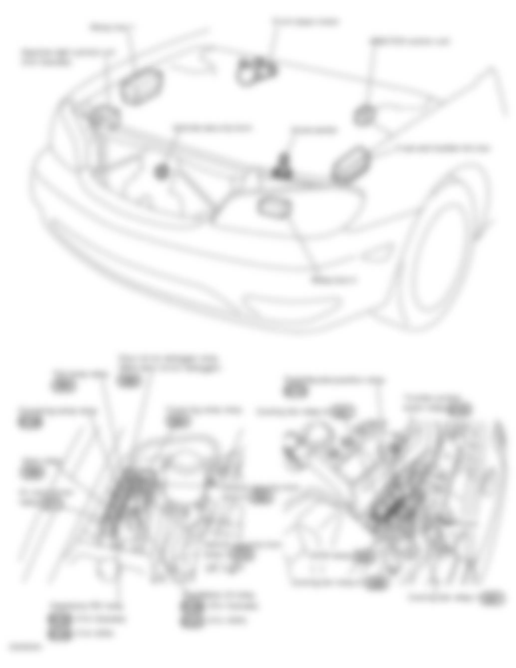
Fig. 3: Infiniti I35 2004 - Component Locations - Dash (1 Of 2)
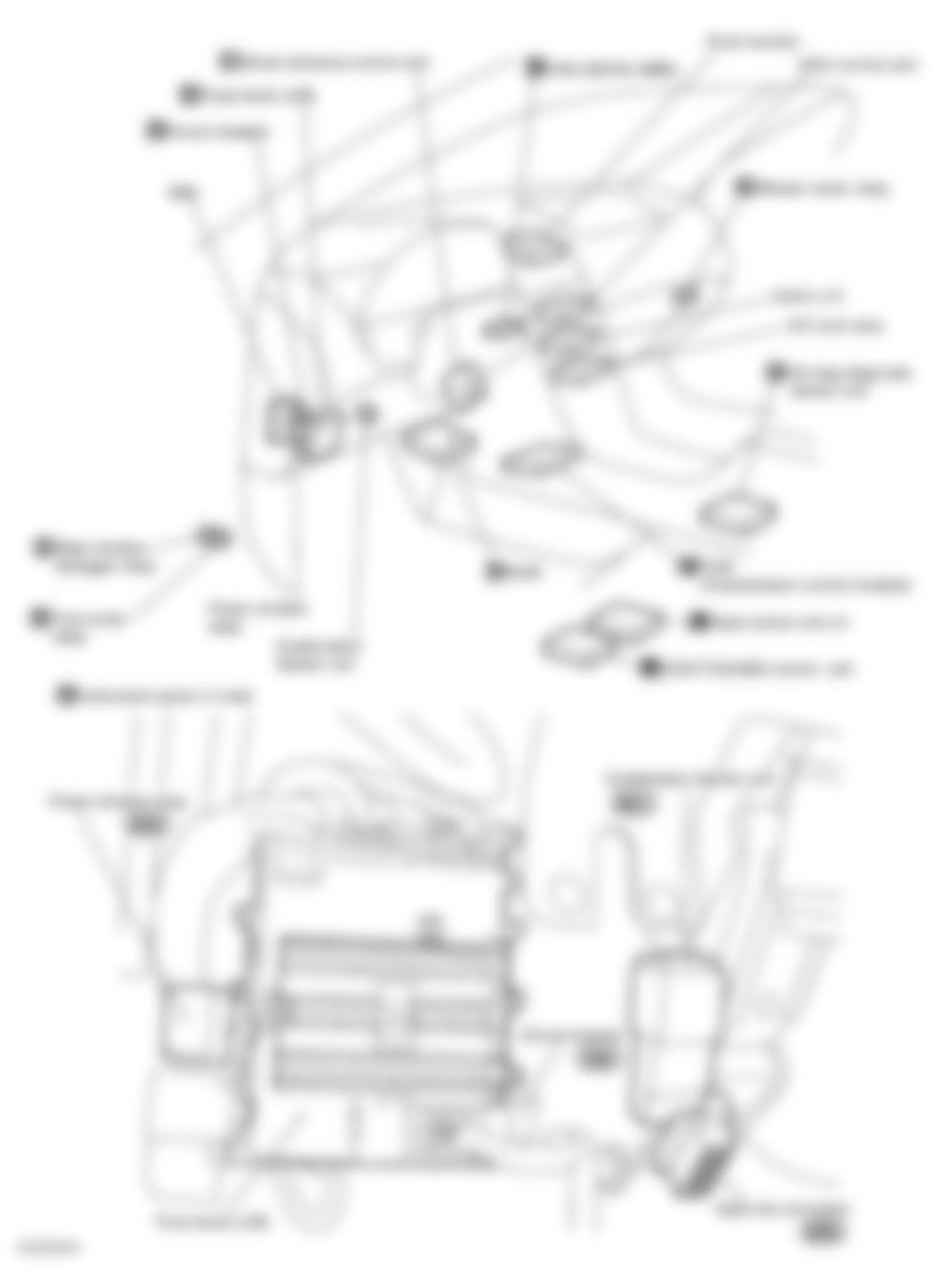
Fig. 4: Infiniti I35 2004 - Component Locations - Dash (2 Of 2)
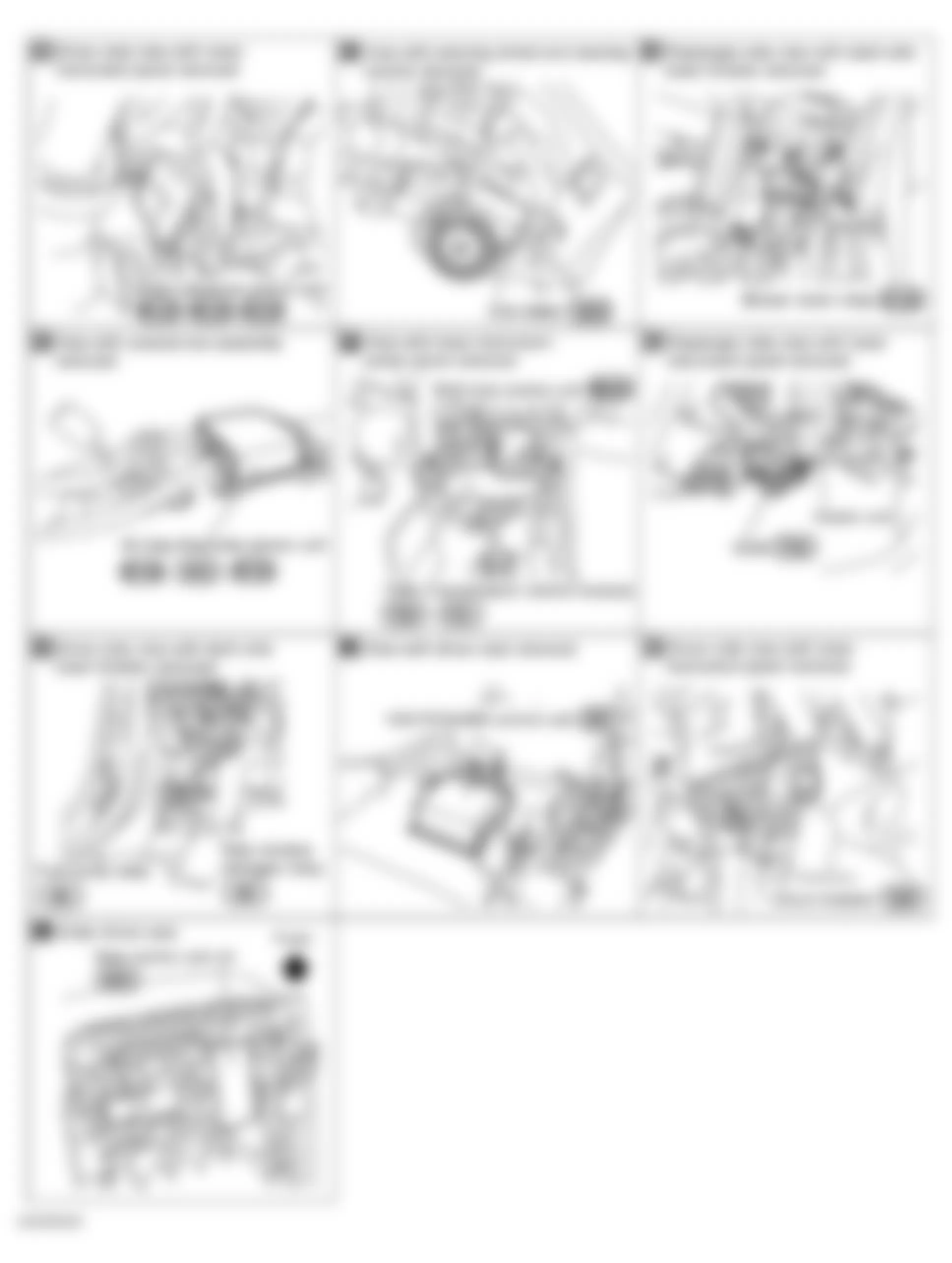
Fig. 5: Infiniti I35 2004 - Component Locations - Rear Of Vehicle
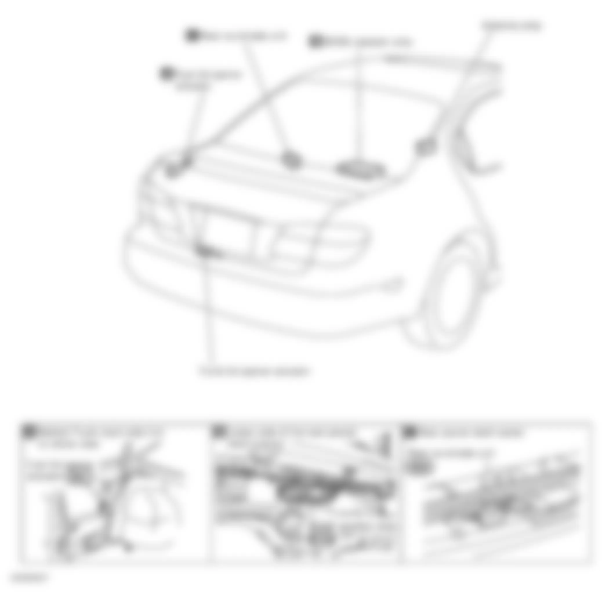
Fig. 6: Infiniti I35 2004 - Component Locations - Front Of Passenger Compartment
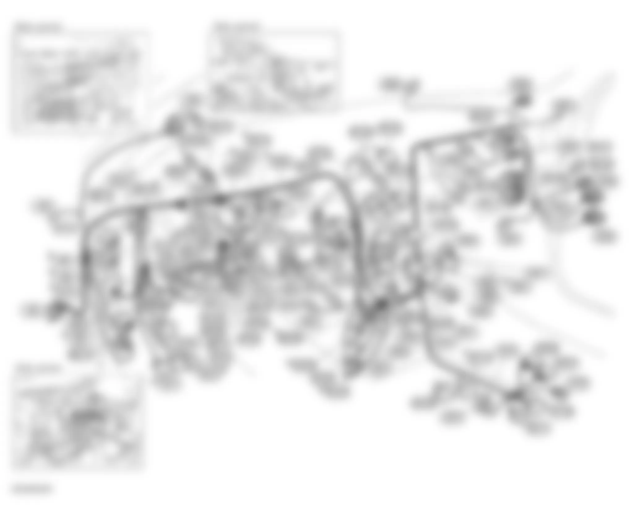
Fig. 7: Infiniti I35 2004 - Component Locations - Engine Compartment
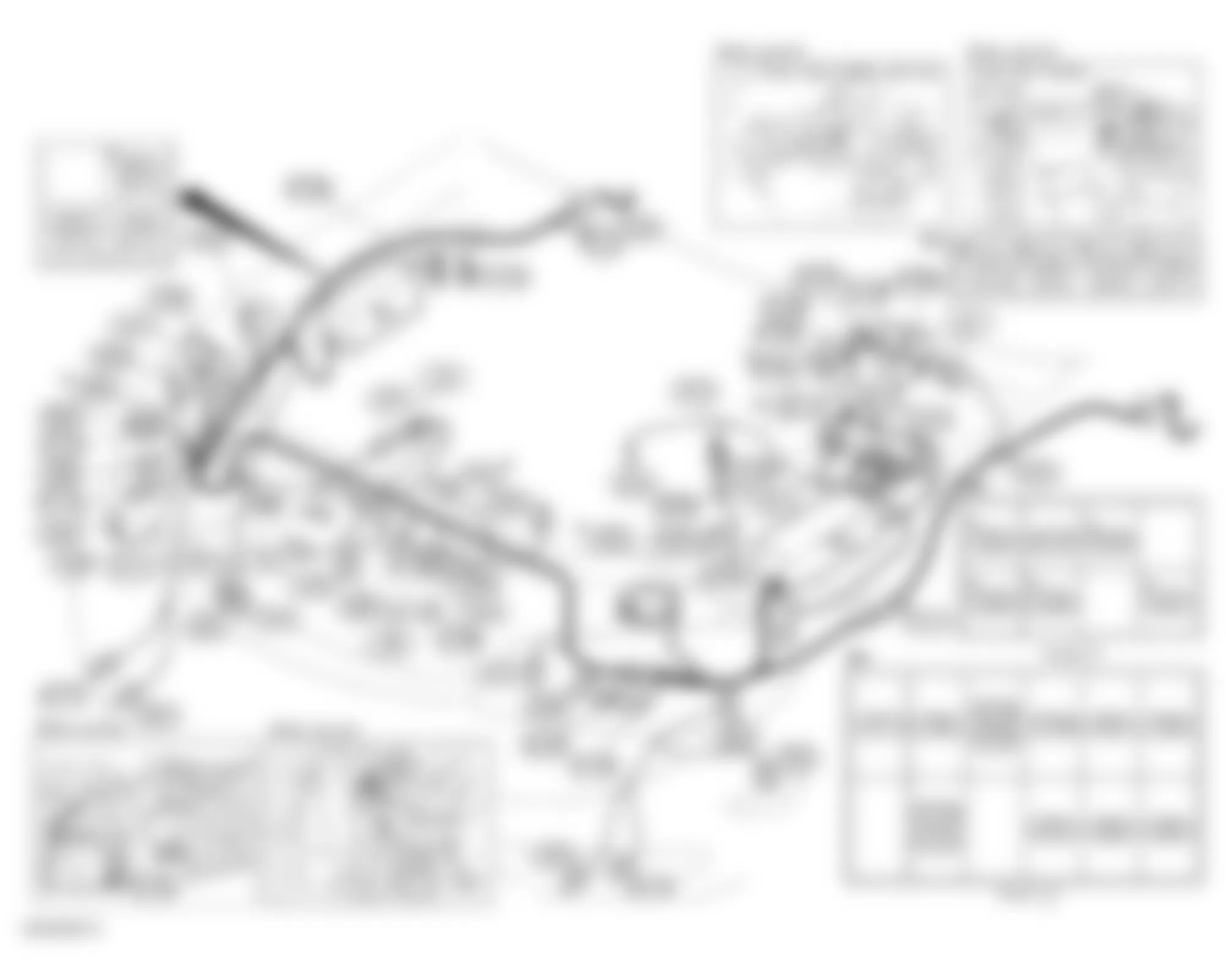
Fig. 8: Infiniti I35 2004 - Component Locations - Dash
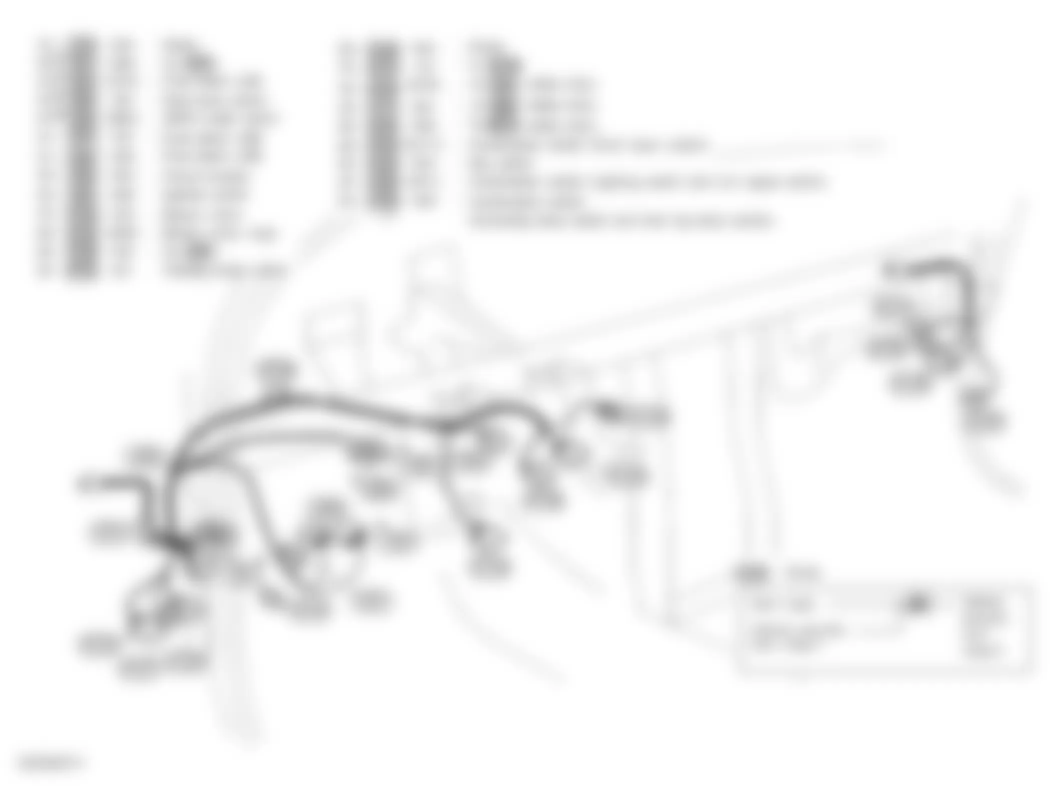
Fig. 9: Infiniti I35 2004 - Component Locations - Engine Compartment
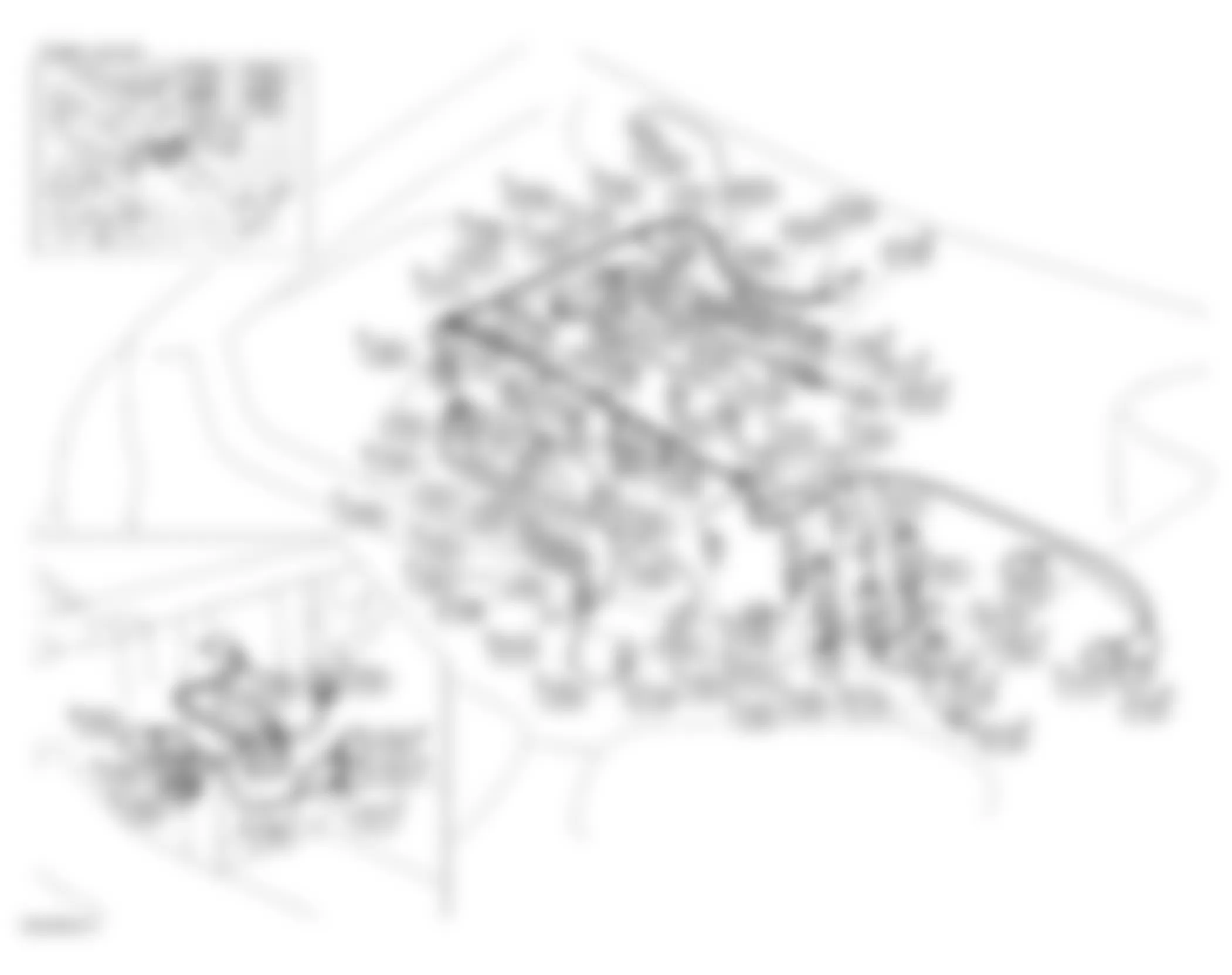
Fig. 10: Infiniti I35 2004 - Component Locations - Body Overview
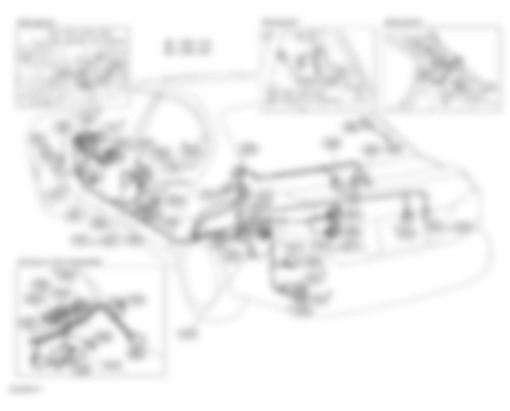
Fig. 11: Infiniti I35 2004 - Component Locations - Body Overview
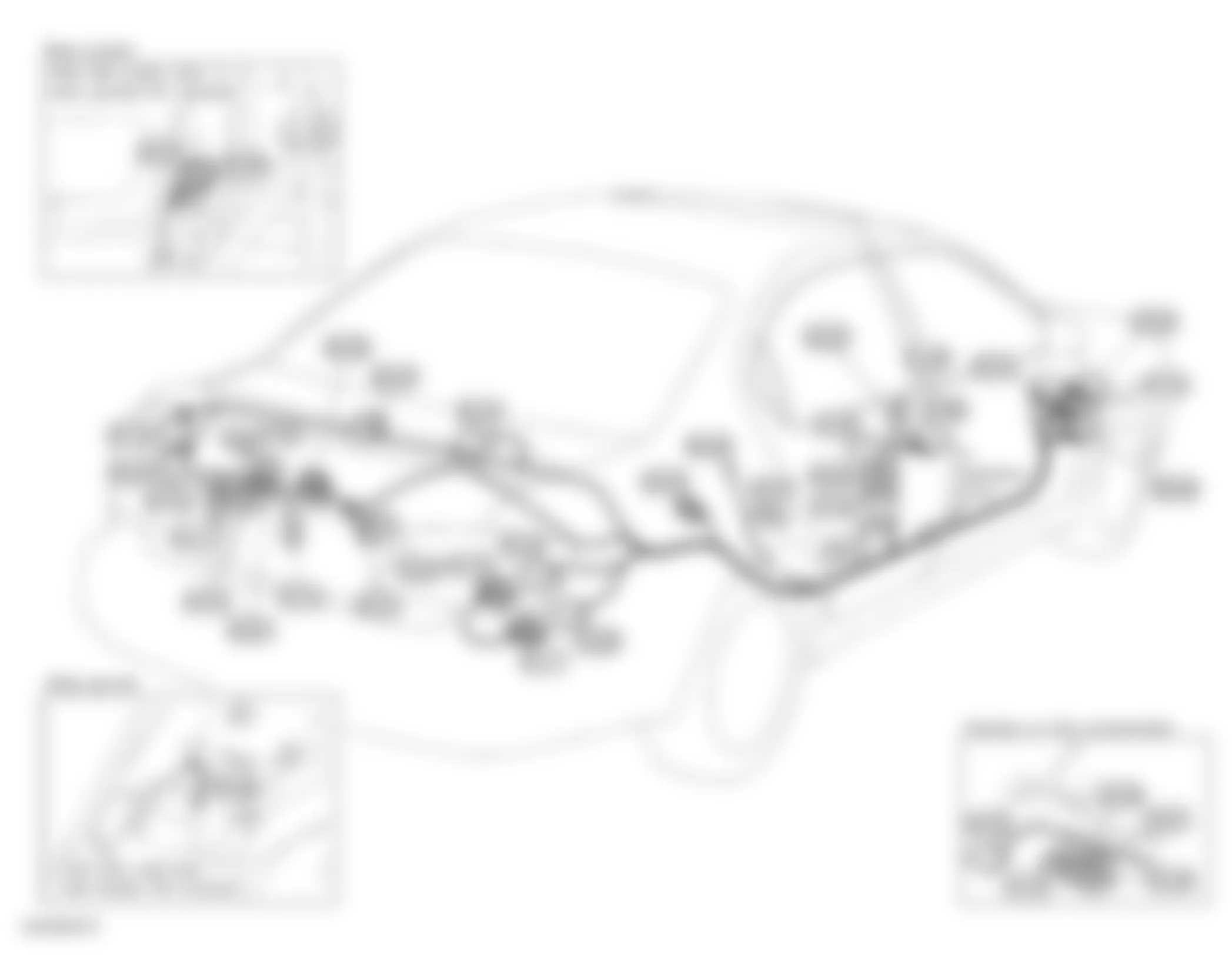
Fig. 12: Infiniti I35 2004 - Component Locations - Rear Compartment
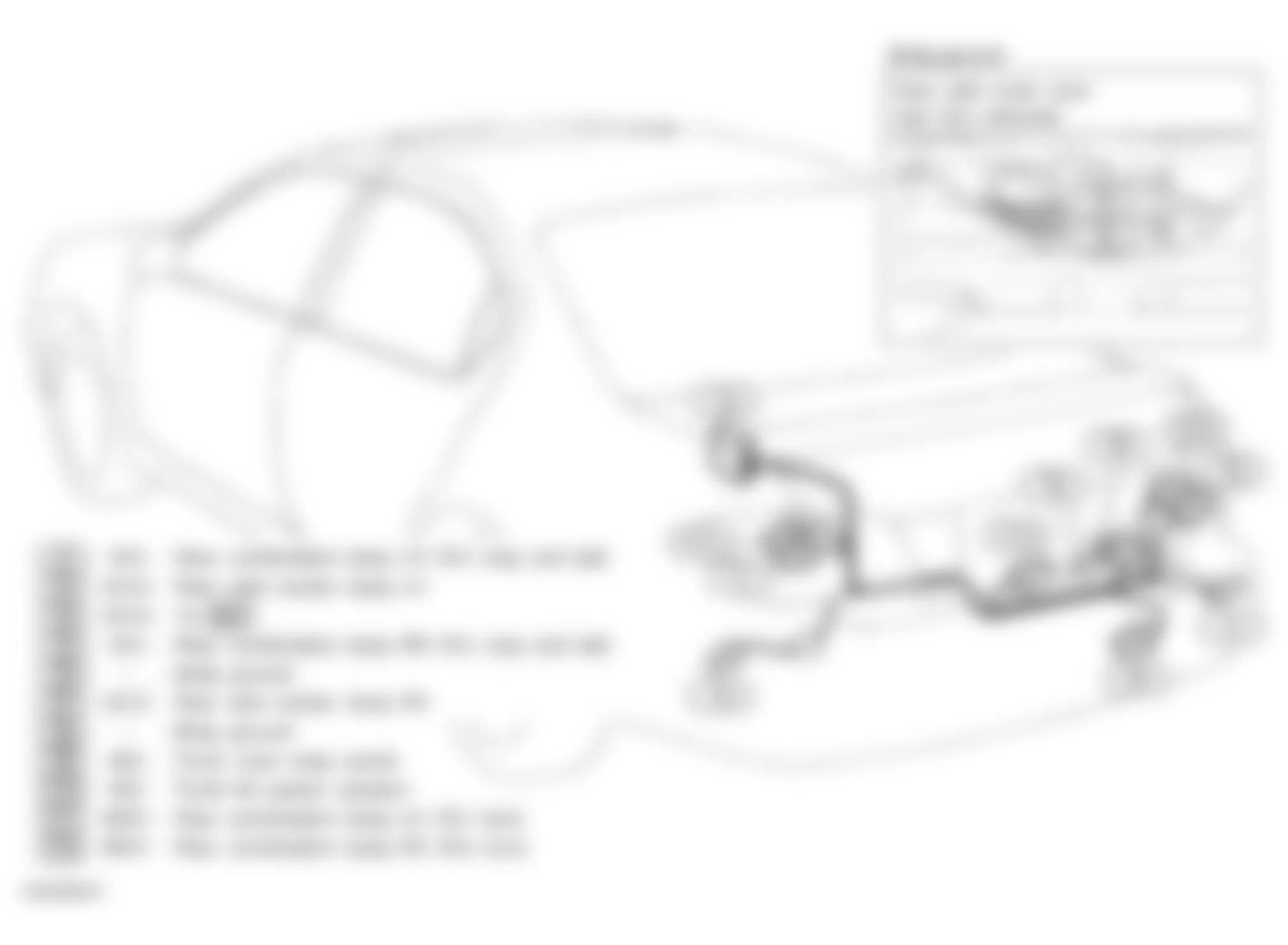
Fig. 13: Infiniti I35 2004 - Component Locations - Headliner
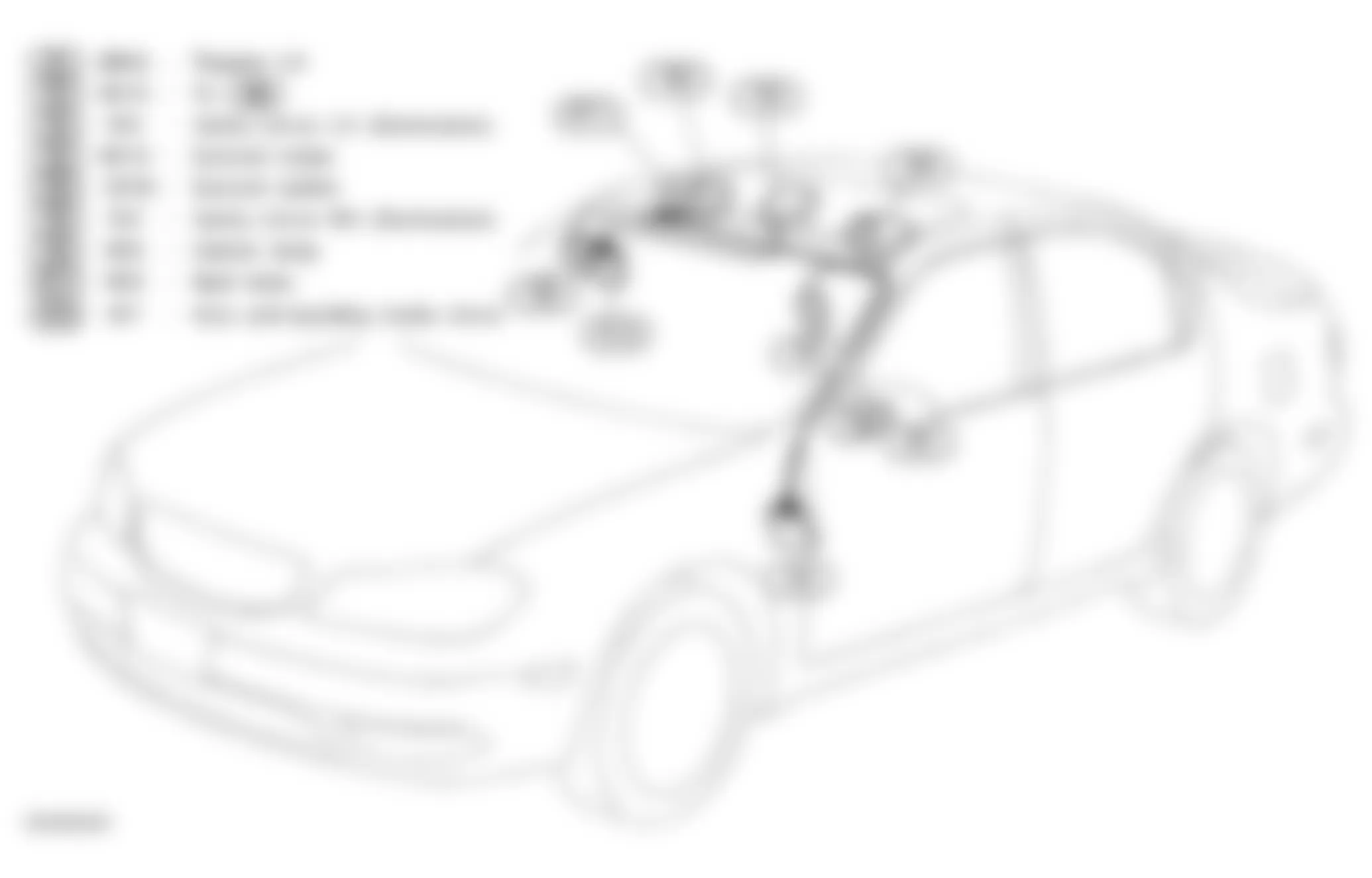
Fig. 14: Infiniti I35 2004 - Component Locations - Left Front Door
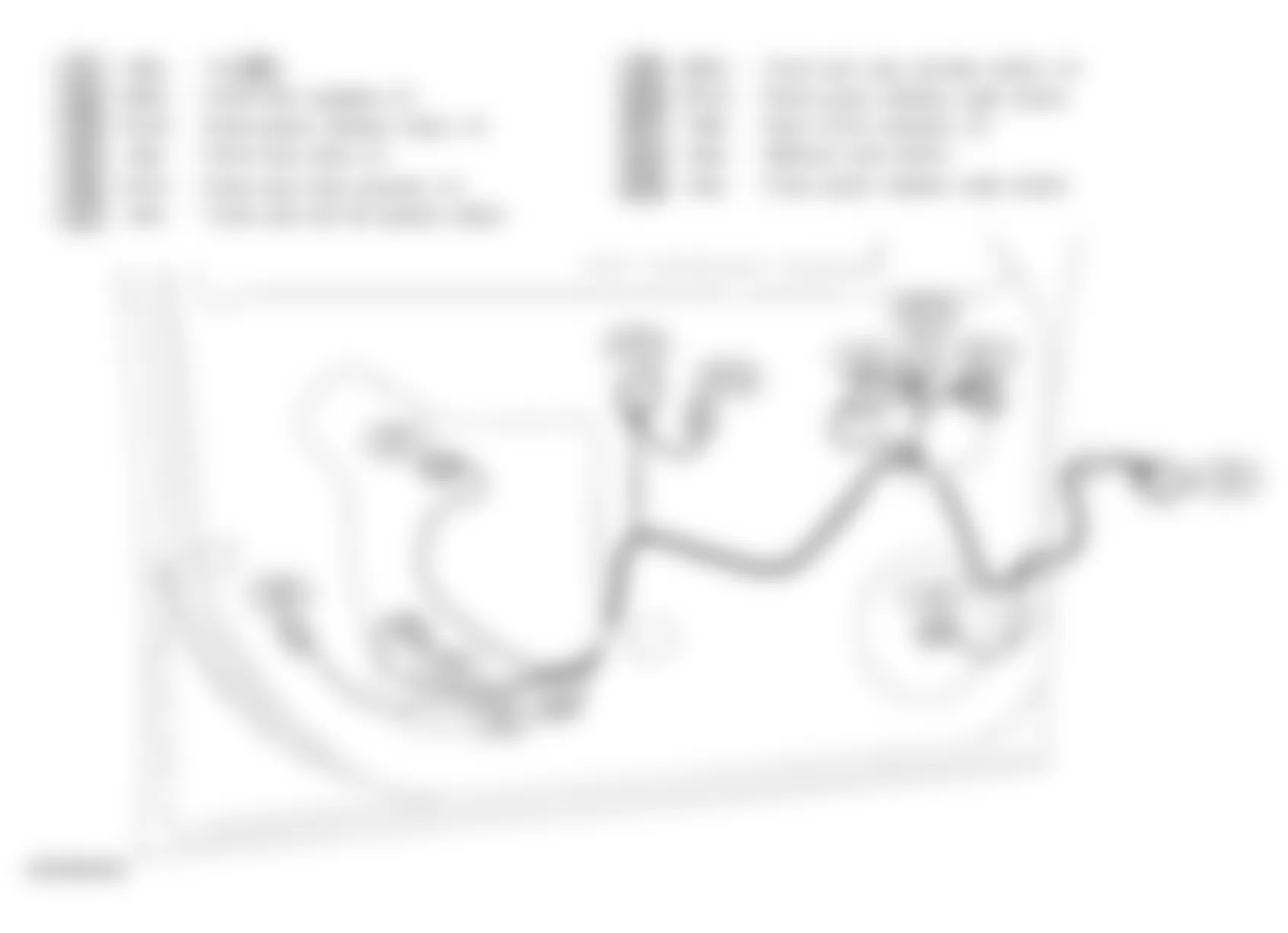
Fig. 15: Infiniti I35 2004 - Component Locations - Right Front Door
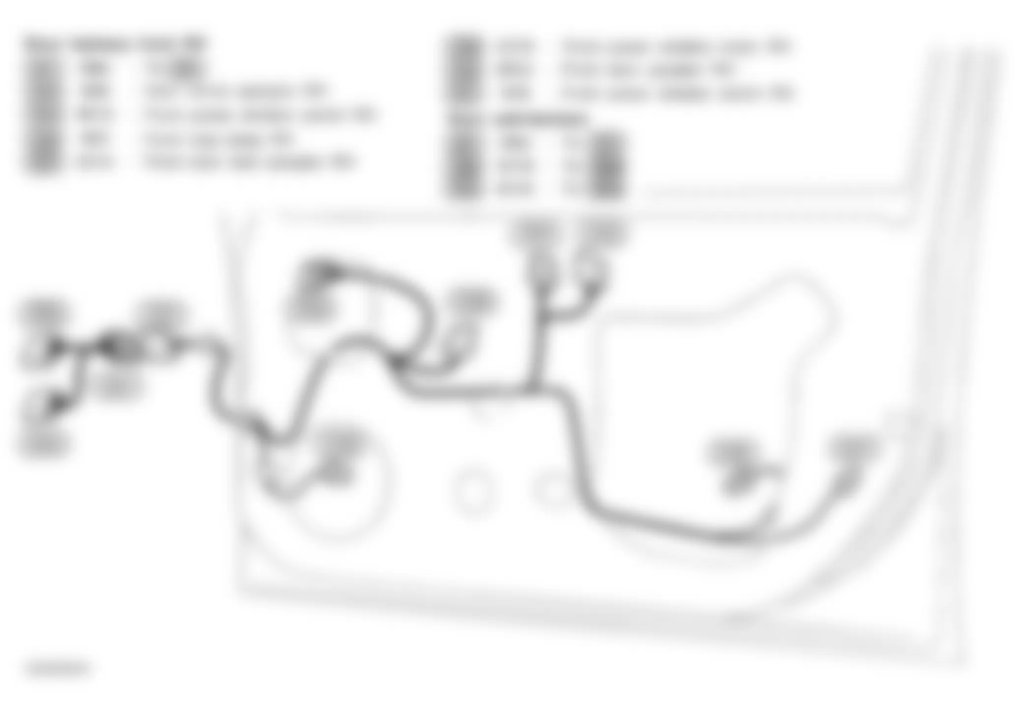
Fig. 16: Infiniti I35 2004 - Component Locations - Left Rear Door
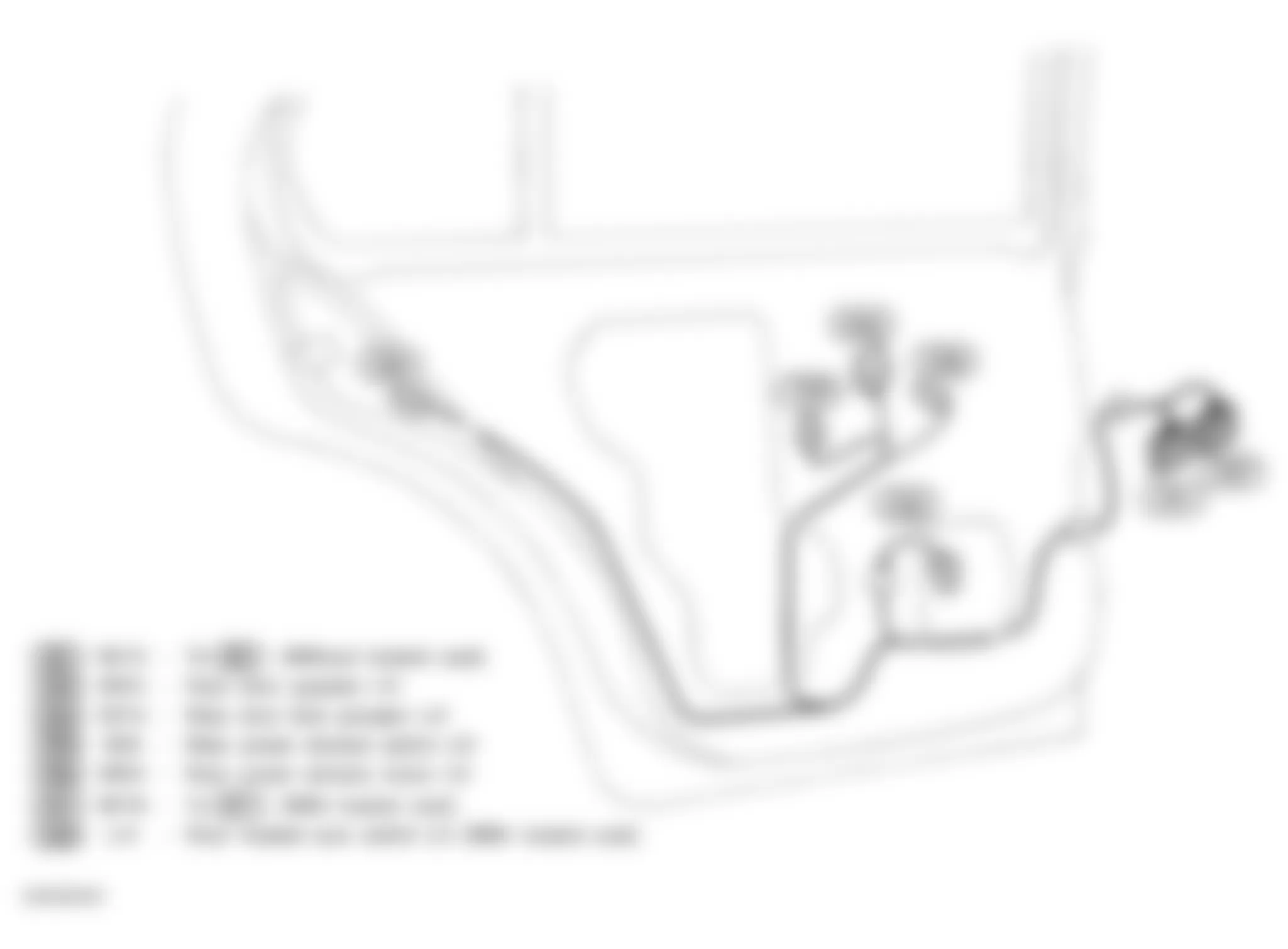
Fig. 17: Infiniti I35 2004 - Component Locations - Right Rear Door