2005 INFINITI Q45
Infiniti Q45 2005 - BUZZERS, RELAYS & TIMERS
Infiniti Q45 2005 BUZZERS, RELAYS & TIMERS LOCATION
Component Location Accessory Relay On back of fuse block (J/B) No. 1. See Fig. 16 . Air Conditioner Relay In fuse, fusible link & relay block (J/B). See Fig. 18 . Back-Up Lamp Relay In fuse, fusible link & relay box. See Fig. 19 . Blower Relay On back of fuse block (J/B) No. 2. See Fig. 17 . Climate Controlled Seat Relay (B324) Right side of luggage compartment. See Fig. 7 . Combination Flasher Unit Behind dash, right side of center console. See Fig. 13 . Cooling Fan Relay-1 Right side of engine compartment. See Fig. 11 . Cooling Fan Relay-2 Left rear of engine compartment. See Fig. 11 . Cooling Fan Relay-3 Left rear of engine compartment. See Fig. 11 . Door Mirror Defogger Relay (B10) Above fuse block (J/B) No. 1. See Fig. 6 . ECM Relay On back of fuse block (J/B) No. 2. See Fig. 17 . Front Fog Lamp Relay Right side of engine compartment. See Fig. 11 . Front Wiper Rain Relay Right side of engine compartment. See Fig. 11 . Front Wiper Relay In fuse, fusible link & relay box. See Fig. 11 . Fuel Pump Relay On back of fuse block (J/B) No. 2. See Fig. 17 . Headlamp Relay-1 In fuse, fusible link & relay block (J/B). See Fig. 18 . Headlamp Relay-2 In fuse, fusible link & relay box. See Fig. 11 . Horn Relay In fuse, fusible link & relay block (J/B). See Fig. 18 . ICC Brake Hold Relay (W/ICC) At right side of engine compartment. See Fig. 11 . Ignition Relay In fuse, fusible link & relay block (J/B). See Fig. 18 . Park/Neutral Position Relay In fuse, fusible link & relay block (J/B). See Fig. 18 . Rear Control Cancel Relay (B253) Behind right rear wheel well. See Fig. 7 . Rear Sunshade Cancel Relay (B254) Behind right rear wheel well. See Fig. 7 . Rear Window Defogger & Door Mirror Defogger Relay (B8) Above fuse block (J/B) No. 1. See Fig. 6 . Tail Lamp Relay In fuse, fusible link & relay block (J/B). See Fig. 18 . Throttle Control Motor Relay In fuse, fusible link & relay box. See Fig. 19 . VDC Relay Box Behind front grille. See Fig. 11 .
Infiniti Q45 2005 - CIRCUIT PROTECTION DEVICES
Infiniti Q45 2005 CIRCUIT PROTECTION DEVICES LOCATION
Component Location Condenser (B228) At base of right "C" pillar. See Fig. 7 . Dropping Resistor (B45) At left rear of luggage compartment. See Fig. 6 . Engine Room Box At right front of engine compartment. See Fig. 11 . Fuse Block At right side of engine compartment. See Fig. 11 . Fuse Block (J/B) No. 1 Behind left end of dash. See Fig. 3 . Fuse Block (J/B) No. 2 (M143) Behind right kick panel. See Fig. 1 . Fuse, Fusible Link & Relay Block (J/B) In engine room box. See Fig. 11 . Fuse, Fusible Link & Relay Box In engine room box. See Fig. 11 . Relay Box-3 Left rear of luggage compartment. See Fig. 11 .
Infiniti Q45 2005 - CONTROL UNITS
Infiniti Q45 2005 CONTROL UNITS LOCATION
Component Location Active Damper Suspension Control Unit Behind left rear shock tower. See Fig. 15 . Air Bag Diagnosis Sensor Unit Under rear of center console. See Fig. 13 . Auto Trunk Control Unit At rear of luggage compartment. See Fig. 15 . AV Control Unit Behind center of dash. See Fig. 13 . AV & NAVI Control Unit (W/NAVI) Under left side of rear parcel shelf. See Fig. 15 . BCM Behind left kick panel. See Fig. 13 . Daytime Light Control Unit (Canada) Left side of engine compartment. See Fig. 11 . Door Mirror Defogger Relay On fuse block (J/B) No.1. See Fig. 12 . Driver Door Control Unit (D8) In driver's door. See Fig. 9 . Driver Side Door Mirror Control Unit (D5) In driver's door. See Fig. 9 . Driver Seat Control Unit Under driver's seat. See Fig. 13 . Dual Mode Muffler Control Unit At right side of trunk. See Fig. 15 . ECM Behind glove box. See Fig. 13 . Fuel Level Sensor & Fuel Pump (B239) At fuel tank. See Fig. 7 . Fuel Pump Control Module At right side of trunk. See Fig. 15 . Headlamp Battery Saver Control Unit Behind dash, left of steering column. See Fig. 13 . ICC Unit At right side of trunk. See Fig. 15 . Left Side Curtain Air Bag Module (B24) At left "B" pillar. See Fig. 6 . Low Tire Pressure Warning Control Unit Behind center of dash. See Fig. 13 . NATS IMMU Behind dash, left of steering column. See Fig. 13 . Passenger Door Control Unit In front passenger's door. See Fig. 20 . Passenger Side Door Mirror Control Unit In front passenger's door. See Fig. 20 . Pre-Crash Seat Belt Control Unit (B318) Right side of luggage compartment. See Fig. 7 . Rear LH Door Control Unit (D58) In left rear door. See Fig. 10 . Rear Power Seat Control Unit (LH) Under left rear seat. See Fig. 14 . Rear Power Seat Control Unit (RH) Under right rear seat. See Fig. 14 . Rear RH Door Control Unit In right rear door. See Fig. 21 . Rear Sunshade Unit At right "C" pillar. See Fig. 15 . Rear View Camera Control Unit At center front of trunk. See Fig. 15 . Right Side Curtain Air Bag Module (B224) At right "C" pillar. See Fig. 7 . Shift Lock Control Unit Behind dash, left of steering column. See Fig. 13 . Steering Lock Control Unit Behind dash, right of steering column. See Fig. 13 . Trunk Closure Control Unit At center rear of trunk. See Fig. 15 . Trunk Lid Opener Relay On back of fuse block (J/B) No.1. See Fig. 16 . VDC/TCS/ABS Control Unit Behind right kick panel. See Fig. 13 . Voice Activated Control Module Left rear of trunk. See Fig. 15 .
Infiniti Q45 2005 - MOTORS
Infiniti Q45 2005 MOTORS LOCATION
Component Location Air Mix Door Motor (Passenger Side) (M107) Behind right side of center console, on heater unit. See Fig. 1 . Auto Trunk Motor (B109) Front of luggage compartment. See Fig. 6 . Blower Motor (M112) Below right side of dash, on intake unit. See Fig. 1 . Condenser (F23) Center rear of engine compartment. See Fig. 5 . Cooling Fan Motor 1 (E103) Front of engine compartment. See Fig. 2 . Cooling Fan Motor 2 (E104) Front of engine compartment. See Fig. 2 . Dual Mode Muffler Actuator (B36) At left rear of luggage compartment. See Fig. 6 . Electric Throttle Control Actuator (F19) On left side of engine. See Fig. 5 . Front Door Lock Actuator (Driver's Side) In driver's door. See Fig. 9 . Front Door Lock Actuator (Passenger Side) In front passenger's door. See Fig. 20 . Front Power Window Motor (Driver's Side) (D7) In driver's door. See Fig. 9 . Front Power Window Motor (Passenger Side) In front passenger's door. See Fig. 20 . Front Shock Absorber Actuator LH At left front shock tower. See Fig. 11 . Front Shock Absorber Actuator RH At right front shock tower. See Fig. 11 . Front Washer Motor (E48) In washer fluid reservoir. See Fig. 2 . Front Wiper Motor On left side of firewall. See Fig. 11 . Fuel Lid Opener Actuator (B259) On right side of trunk. See Fig. 15 . Intake Door Motor (M118) Under right side of dash, on intake unit. See Fig. 1 . Left Front Shock Absorber Actuator (E61) On top of left shock tower, under hood. See Fig. 2 . Left Rear Shock Absorber Actuator (B26) On top of left rear shock tower. See Fig. 6 . Mode Door Motor (Passenger Side) (M106) Behind right side of dash. See Fig. 1 . Pre-Crash Seat Belt Motor (Left) (B117) Under driver's seat. See Fig. 6 . Pre-Crash Seat Belt Motor (Right) (B317) Under right front seat. See Fig. 7 . Rear Door Lock Actuator LH (D61) In left rear door. See Fig. 10 . Rear Door Lock Actuator RH In right rear door. See Fig. 21 . Rear Power Window Motor LH (D57) In left rear door. See Fig. 10 . Rear Power Window Motor RH In right rear door. See Fig. 21 . Rear Vent Door Motor (M93) Behind left front of center console. See Fig. 1 . Right Front Shock Absorber Actuator (E31) On top of right shock tower, under hood. See Fig. 2 . Right Rear Shock Absorber Actuator On top of right rear shock absorber. See Fig. 15 . Starter Motor Right rear of engine block. See Fig. 4 . Sun Roof Motor Assembly (R8) At front of sun roof opening. See Fig. 8 . Telescopic Motor (M60) At right side of steering column. See Fig. 1 . Tilt Motor (M58) At right side of steering column. See Fig. 1 . Trunk Lid Opener Actuator Center of deck lid. See Fig. 15 . VDC Actuator Right rear of engine compartment. See Fig. 11 .
Infiniti Q45 2005 - SENDING UNITS & SENSORS
Infiniti Q45 2005 SENDING UNITS & SENSORS LOCATION
Component Location Accelerator Pedal Position Sensor (M45) Under left side of dash. See Fig. 1 . Ambient Sensor (E58) At center front of engine compartment. See Fig. 2 . Brake Pedal Stroke Sensor (M405) Under left side of dash. See Fig. 1 . Brake Pressure Sensor (E82) At left rear of engine compartment. See Fig. 2 . Camshaft Position Sensor (PHASE) (F4) On front of left cylinder head. See Fig. 5 . Crankshaft Position Sensor (POS) On rear of cylinder block. See Fig. 4 . Crash Zone Sensor (E60) At center front of engine compartment. See Fig. 2 . Engine Coolant Temperature Sensor (F262) On top rear of engine. See Fig. 5 . EVAP Control System Pressure Sensor (B403) In EVAP purge line. See Fig. 7 . Front Vertical G Sensor (B3) At base of left kick panel. See Fig. 6 . Front Wheel Sensor (LH) (E70) At left front hub assembly. See Fig. 2 . Front Wheel Sensor RH (E20) At right front hub assembly. See Fig. 2 . Headlamp Aiming Sensor (B622) At rear of vehicle. See Fig. 6 . Heated Oxygen Sensor Bank No. 1 Sensor No. 1 (F22) On inlet of left manifold three-way catalyst. See Fig. 5 . Heated Oxygen Sensor Bank No. 1 Sensor No. 2 On inlet of right manifold three-way catalyst. See Fig. 4 . Heated Oxygen Sensor Bank No. 2 Sensor No. 1 (F42) On outlet of left manifold three-way catalyst. See Fig. 5 . Heated Oxygen Sensor Bank No. 2 Sensor No. 2 On outlet of right manifold three-way catalyst. See Fig. 4 . ICC Sensor (W/ICC) (E52) At front center of engine compartment. See Fig. 2 . Intake Valve Timing Control Position Sensor (Bank No. 1) (F12) On front of left cylinder head. See Fig. 5 . Intake Valve Timing Control Position Sensor (Bank No. 2) (F30) On front of right cylinder head. See Fig. 5 . In-Vehicle Sensor (M68) Below lower left side of dash. See Fig. 1 . Knock Sensor (Bank No. 1) (F242) Below left side of intake manifold. See Fig. 5 . Knock Sensor (Bank No. 2) (F243) Below right side of intake manifold. See Fig. 5 . Left Side Air Bag (Satellite) Sensor (B18) At left "B" pillar. See Fig. 6 . Mass Airflow Sensor (F7) Between air duct & air cleaner housing. See Fig. 5 . Optical Sensor (M110) On top right side of dash. See Fig. 1 . Power Steering Pressure Sensor (E308) At lower right front of engine. See Fig. 4 . Rain Sensor (R20) On windshield. See Fig. 8 . Rear Vertical G Sensor (B227) At right "C" pillar. See Fig. 7 . Rear Wheel Sensor (B35) At left rear of luggage compartment. See Fig. 6 . Refrigerant Pressure Sensor (E49) At front right of engine compartment, near condenser. See Fig. 2 . RH Side Air Bag (Satellite) Sensor (B218) At base of right "B" pillar. See Fig. 7 . Steering Angle Sensor (M52) At right side of steering column. See Fig. 1 . Sun Load Sensor (M44) Behind left side of dash. See Fig. 1 . Telescopic Sensor (M59) At right side of steering column. See Fig. 1 . Tilt Sensor (M57) At right side of steering column. See Fig. 1 . Yaw Rate & G Sensor (M99) Under center console. See Fig. 1 .
Infiniti Q45 2005 - SOLENOIDS & SOLENOID VALVES
Infiniti Q45 2005 SOLENOIDS & SOLENOID VALVES LOCATION
Component Location Compressor (EVC Solenoid Valve) (F6) Left front of engine compartment. See Fig. 5 . Compressor (Magnet Clutch) (F2) Left front of engine compartment. See Fig. 5 . EVAP Canister Purge Volume Control Solenoid Valve (F25) On top right rear of engine. See Fig. 5 . EVAP Canister Vent Control Valve (B402) Under rear of vehicle, on EVAP canister. See Fig. 7 . Injector No. 1 (F202) Top left side of engine. See Fig. 5 . Injector No. 2 (F222) Top right side of engine. See Fig. 5 . Injector No. 3 (F203) Top left side of engine. See Fig. 5 . Injector No. 4 (F223) Top right side of engine. See Fig. 5 . Injector No. 5 (F203) Top left side of engine. See Fig. 5 . Injector No. 7 (F205) Top left side of engine. See Fig. 5 . Injector No. 8 (F225) Top right side of engine. See Fig. 5 . Intake Valve Timing Control Solenoid Valve (Bank No. 1) (F13) On top front of left cylinder head. See Fig. 5 . Intake Valve Timing Control Solenoid Valve (Bank No. 2) (F31) On top front of right cylinder head. See Fig. 5 . Power Steering Solenoid Valve (F3) On steering rack assembly. See Fig. 5 . Vacuum Cut Valve By-Pass Valve (B404) Under rear of vehicle, forward of EVAP canister. See Fig. 7 . VIAS Control Solenoid Valve (F29) Top front center of engine. See Fig. 5 .
Infiniti Q45 2005 - SWITCHES
Infiniti Q45 2005 SWITCHES LOCATION
Component Location ASCD Brake Switch (M403) On bracket, above brake pedal. See Fig. 1 . Brake Fluid Level Switch (E74) At left rear of engine compartment, on brake fluid reservoir. See Fig. 2 . Door Lock Assembly Rear LH (Door Switch) (D62) In left rear door. See Fig. 10 . Door Lock Assembly Rear RH (Door Switch) In right rear door. See Fig. 21 . Front Door Switch (Passenger Side) (B220) At base of right "B" pillar. See Fig. 7 . Hood Switch Near hood lock stay. See Fig. 11 . ICC Brake Switch (M404) On bracket, above brake pedal. See Fig. 1 . Oil Pressure Switch (F1) On front center of engine. See Fig. 5 . Parking Brake Switch (M8) Behind dash, at park brake assembly. See Fig. 1 . Stop Lamp Switch (M402) On bracket, above brake pedal. See Fig. 1 . Trunk Lid Close Switch (B309) Center of trunk lid. See Fig. 7 . Trunk Lid Key Cylinder Switch (Unlock Switch) (B307) Center of trunk lid. See Fig. 7 . Trunk Lid Lock Switch (W Auto Trunk) Center of trunk lid. See Fig. 7 . Trunk Lid Striker Switch (B55) Above center of rear bumper. See Fig. 6 . Washer Level Switch (E47) In washer fluid reservoir. See Fig. 2 .
Infiniti Q45 2005 - MISCELLANEOUS
Infiniti Q45 2005 MISCELLANEOUS LOCATION
Component Location Alternator (E309) Right front of engine. See Fig. 4 . Antenna Amp. At right "C" pillar. See Fig. 15 . Auto Trunk Buzzer 1 (B104) At front of luggage compartment. See Fig. 6 . Auto Trunk Buzzer 2 In front of luggage compartment. See Fig. 6 . BOSE Speaker Amp. At center front of trunk. See Fig. 15 . Brake Booster (E81) Left rear of engine compartment. See Fig. 2 . Condenser (Rear Window Defogger) (B25) At left "C" pillar. See Fig. 6 . Data Link Connector Under left side of dash. See Fig. 13 . Front LH Seat Belt Pre-Tensioner (B19) At left "B" pillar. See Fig. 6 . Front LH Side Air Bag Module (B14) At left side of vehicle. See Fig. 6 . Front RH Seat Belt Pre-Tensioner At base of right "B" pillar. See Fig. 7 . Front RH Side Air Bag Module (B214) At right side of dash. See Fig. 7 . Horn (High) (E63) Left front of engine compartment. See Fig. 2 . Horn (Low) (E43) At right front radiator support. See Fig. 2 . ICC Warning Chime (M37) Under left side of dash, near ASCD control unit. See Fig. 1 . Ignition Coil (With Power Transistor) No. 1 (F15) Top left side of engine. See Fig. 5 . Ignition Coil (With Power Transistor) No. 2 (F35) Top right side of engine. See Fig. 5 . Ignition Coil (With Power Transistor) No. 3 (F16) Top left side of engine. See Fig. 5 . Ignition Coil (With Power Transistor) No. 4 (F36) Top right side of engine. See Fig. 5 . Ignition Coil (With Power Transistor) No. 5 (F17) Top left side of engine. See Fig. 5 . Ignition Coil (With Power Transistor) No. 6 (F37) Top right side of engine. See Fig. 5 . Ignition Coil (With Power Transistor) No. 7 (F18) Top left side of engine. See Fig. 5 . Ignition Coil (With Power Transistor) No. 8 (F38) Top right side of engine. See Fig. 5 . Microphone (R10) Front of roof, under headliner. See Fig. 8 . NATS Antenna Amplifier (M65) Behind right side of dash. See Fig. 1 . Remote Keyless Entry Receiver (B246) At left "C" pillar. See Fig. 7 .
Infiniti Q45 2005 - CONNECTORS
Infiniti Q45 2005 CONNECTORS LOCATION
Component Location B6 (Gray, 24 Pin) Behind left kick panel. See Fig. 6 . B7 (White, 24 Pin) Behind left kick panel. See Fig. 6 . B11 (White, 20 Pin) Behind left kick panel. See Fig. 6 . B12 (Brown, 6 Pin) Behind left kick panel. See Fig. 6 . B21 (White, 15 Pin) At left "B" pillar. See Fig. 6 . B22 (Gray, 15 Pin) At left "B" pillar. See Fig. 6 . B31 (Brown, 24 Pin) Left side of dash. See Fig. 6 . B61 (White, 12 Pin) Behind right taillight assembly. See Fig. 6 . B62 (Brown, 8 Pin) Behind right taillight assembly. See Fig. 6 . B63 (White, 10 Pin) Behind right taillight assembly. See Fig. 6 . B64 (White, 16 Pin) Behind right taillight assembly. See Fig. 6 . B65 (White, 2 Pin) Behind right taillight assembly. See Fig. 6 . B66 (White, 3 Pin) Behind right taillight assembly. See Fig. 6 . B80 (White, 4 Pin) Center of floor pan. See Fig. 6 . B121 (Brown, 8 Pin) At rear of vehicle. See Fig. 6 . B202 (White, 4 Pin) At right front door sill. See Fig. 7 . B203 (White, 4 Pin) At right front door sill. See Fig. 7 . B204 (White, 12 Pin) Behind right kick panel. See Fig. 7 . B205 (White, 20 Pin) Behind right kick panel. See Fig. 7 . B207 (White, 3 Pin) Behind right kick panel. See Fig. 7 . B208 (Brown, 24 Pin) Behind right kick panel. See Fig. 7 . B209 (White, 4 Pin) Behind right kick panel. See Fig. 7 . B210 (Gray, 6 Pin) Behind right kick panel. See Fig. 7 . B211 (SMJ) Behind right kick panel. See Fig. 7 . B221 (White, 15 Pin) At right "B" pillar. See Fig. 7 . B222 (Gray, 15 Pin) At right "B" pillar. See Fig. 7 . B251 (Light Blue, 8 Pin) At right side of trunk. See Fig. 7 . B261 (White, 12 Pin) Behind right rear taillight. See Fig. 7 . B262 (Brown, 8 Pin) Behind right rear taillight. See Fig. 7 . B263 (White, 10 Pin) Behind right rear taillight. See Fig. 7 . B264 (White, 16 Pin) Behind right rear taillight. See Fig. 7 . B265 (White, 2 Pin) Behind right rear taillight. See Fig. 7 . B266 (White, 3 Pin) Behind right rear taillight. See Fig. 7 . B280 (White, 4 Pin) Under left front seat. See Fig. 7 . B401 (Light Blue, 8 Pin) At right side of trunk. See Fig. 7 . B501 (White, 12 Pin) Behind rear center console. See Fig. 6 . B621 (Brown, 8 Pin) At rear of vehicle. See Fig. 6 . D1 (SMJ) Behind left kick panel. See Fig. 8 . D31 (SMJ) Behind right kick panel. See Fig. 20 . D51 (White, 30 Pin) At left "B" pillar. See Fig. 10 . D71 (White, 30 Pin) At right "B" pillar. See Fig. 21 . E32 (Light Blue, 8 Pin) At right side of engine compartment. See Fig. 2 . E33 (Gray, 10 Pin) At right side of engine compartment. See Fig. 2 . E34 (Green, 10 Pin) At right side of engine compartment. See Fig. 2 . E35 (Gray, 9 Pin) At right side of engine compartment. See Fig. 2 . E205 (SMJ) Behind lower left side of dash. See Fig. 3 . E206 (Yellow, 4 Pin) Behind lower left side of dash. See Fig. 3 . E211 (White, 20 Pin) Behind left kick panel. See Fig. 3 . E212 (Brown, 6 Pin) Behind left kick panel. See Fig. 3 . E224 (White, 12 Pin) Behind right kick panel. See Fig. 3 . E225 (White, 20 Pin) Behind right kick panel. See Fig. 3 . E305 (Gray, 9 Pin) At right side of engine compartment. See Fig. 4 . E315 (Gray, 10 Pin) At front of engine compartment. See Fig. 4 . F5 (Gray, 10 Pin) At left front of engine compartment. See Fig. 5 . F21 (Green, 6 Pin) On rear of engine. See Fig. 5 . F24 (Light Blue, 2 Pin) On left rear of engine. See Fig. 5 . F32 (Light Blue, 8 Pin) At right front of engine compartment. See Fig. 5 . F33 (Gray, 10 Pin) At right front of engine compartment. See Fig. 5 . F34 (Green, 10 Pin) At right front of engine compartment. See Fig. 5 . F40 (Dark Gray, 4 Pin) On right rear of engine. See Fig. 5 . F41 (Green, 6 Pin) On right side of engine. See Fig. 5 . F101 (SMJ) Behind right side of dash. See Fig. 5 . F105 (SMJ) Behind right kick panel. See Fig. 5 . F201 (Green, 6 Pin) At left rear of engine. See Fig. 5 . F221 (Green, 6 Pin) At rear of engine. See Fig. 5 . F241 (Blue, 4 Pin) On right rear of engine. See Fig. 5 . F261 (Light Blue, 2 Pin) On left rear of engine. See Fig. 5 . M5 (SMJ) Behind left kick panel. See Fig. 1 . M6 (Gray, 24 Pin) Behind left kick panel. See Fig. 1 . M7 (White, 24 Pin) Behind left kick panel. See Fig. 1 . M11 (SMJ) Behind left kick panel. See Fig. 1 . M15 (SMJ) Behind lower left end of dash. See Fig. 1 . M16 (Yellow, 4 Pin) Behind lower left end of dash. See Fig. 1 . M23 (White, 18 Pin) Behind upper left end of dash. See Fig. 1 . M39 (White, 8 Pin) Behind left side of dash. See Fig. 1 . M40 (White, 8 Pin) Behind left side of dash. See Fig. 1 . M61 (White, 10 Pin) Behind left side of dash. See Fig. 1 . M111 (White, 6 Pin) Behind upper center of dash. See Fig. 1 . M132 (White, 24 Pin) Behind right kick panel. See Fig. 1 . M135 (SMJ) Behind right kick panel. See Fig. 1 . M137 (White, 3 Pin) Behind right kick panel. See Fig. 1 . M138 (Brown, 24 Pin) Behind right kick panel. See Fig. 1 . M139 (White, 4 Pin) Behind right kick panel. See Fig. 1 . M140 (Gray, 6 Pin) Behind right kick panel. See Fig. 1 . M141 (SMJ) Behind right kick panel. See Fig. 1 . M142 (SMJ) Behind right kick panel. See Fig. 1 . M401 (White, 10 Pin) Behind instrument cluster. See Fig. 1 . M411 (White, 6 Pin) Behind upper center of dash. See Fig. 1 . R3 (White, 18 Pin) Behind upper left end of dash. See Fig. 8 . R14 (White, 2 Pin) At center of windshield headliner. See Fig. 8 . R15 (White, 2 Pin) At center of windshield headliner. See Fig. 8 .
Infiniti Q45 2005 - GROUNDS
Infiniti Q45 2005 GROUNDS LOCATION
Component Location B16 Under left front door sill. See Fig. 6 . B17 Under left front door sill. See Fig. 6 . B57 At center rear of vehicle. See Fig. 6 . B122 On left rocker panel. See Fig. 6 . B216 Under right front door sill. See Fig. 7 . B217 Under right front door sill. See Fig. 7 . B256 At right front of trunk. See Fig. 7 . B322 Right rocker panel. See Fig. 7 . B323 Right "C" pillar. See Fig. 7 . B422 At base of right "C" pillar. See Fig. 7 . E24 On right front strut tower. See Fig. 2 . E42 On right front fenderwell, forward of engine room box. See Fig. 2 . E44 On right front fenderwell, forward of engine room box. See Fig. 2 . E59 At center front of engine compartment. See Fig. 2 . E62 On left front fenderwell, near engine oil level gauge. See Fig. 2 . E67 On left front strut tower. See Fig. 2 . E307 At right front of engine compartment, near battery. See Fig. 4 . F8 At left front of engine compartment, near engine oil level gauge. See Fig. 5 . F9 At left front of engine compartment, near engine oil level gauge. See Fig. 5 . M24 Behind left side of dash. See Fig. 1 . M25 Behind left side of dash. See Fig. 1 . M114 Behind right side of dash. See Fig. 1 . M115 Behind right side of dash. See Fig. 1 .
Infiniti Q45 2005 - COMPONENT LOCATION GRAPHICS
NOTE:
Fig.res may show multiple component locations. - appropriate table for proper figure references.

Fig. 1: Infiniti Q45 2005 - Component Locations - Dash
Fig. 2: Infiniti Q45 2005 - Component Locations - Engine Compartment
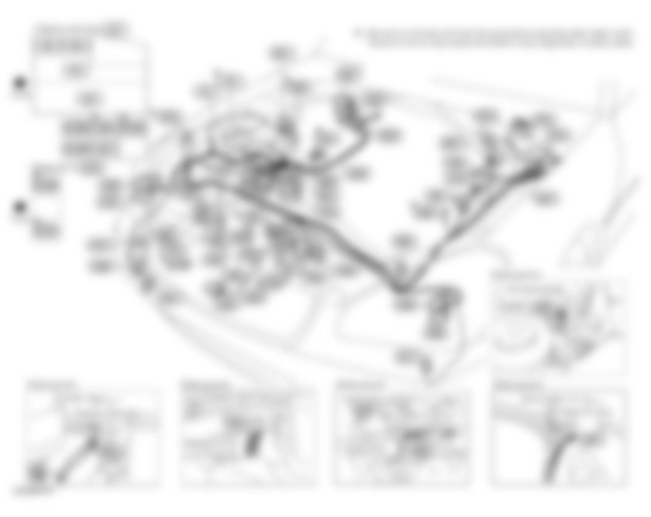
Fig. 3: Infiniti Q45 2005 - Component Locations - Dash
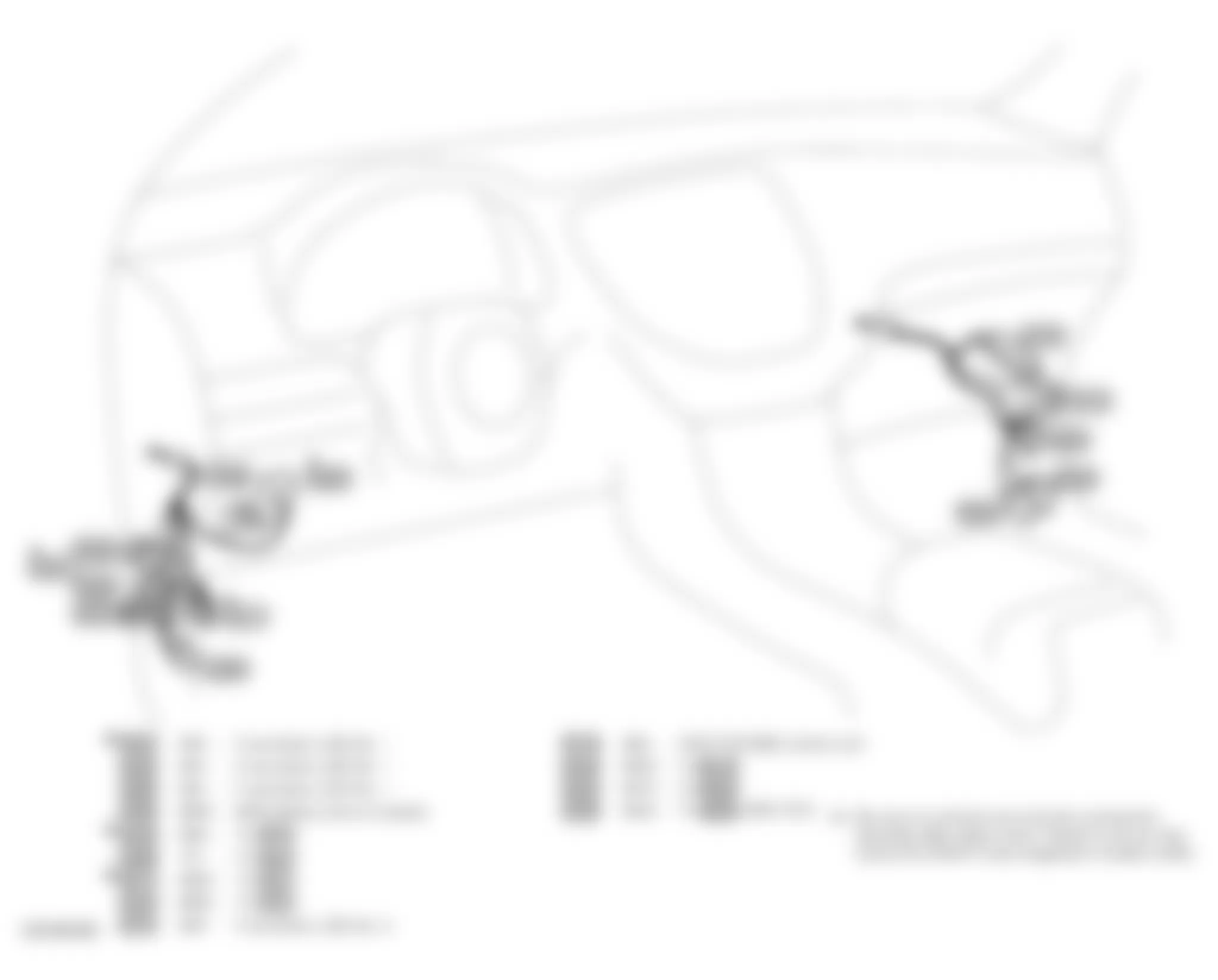
Fig. 4: Infiniti Q45 2005 - Component Locations - Engine
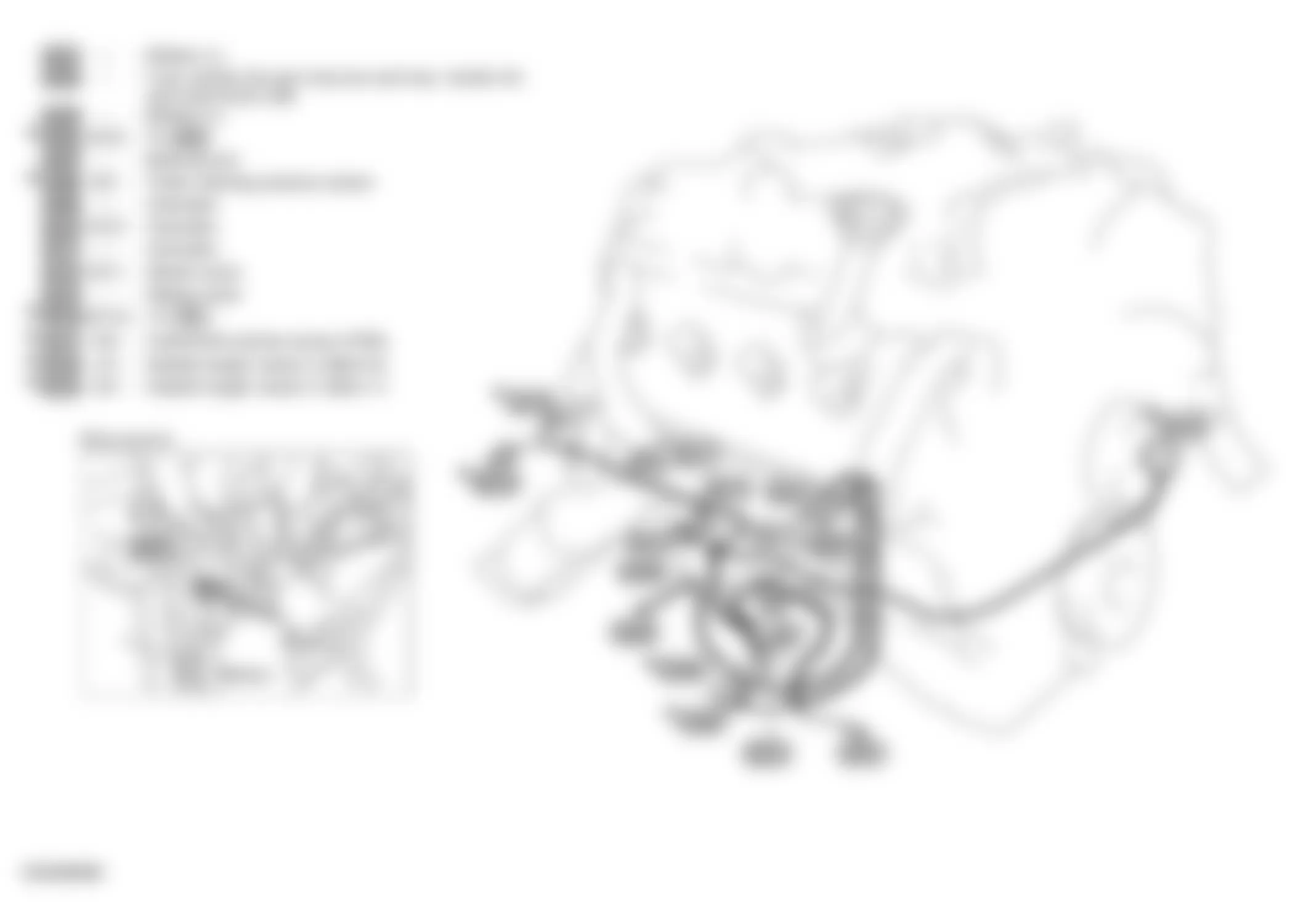
Fig. 5: Infiniti Q45 2005 - Component Locations - Engine Compartment
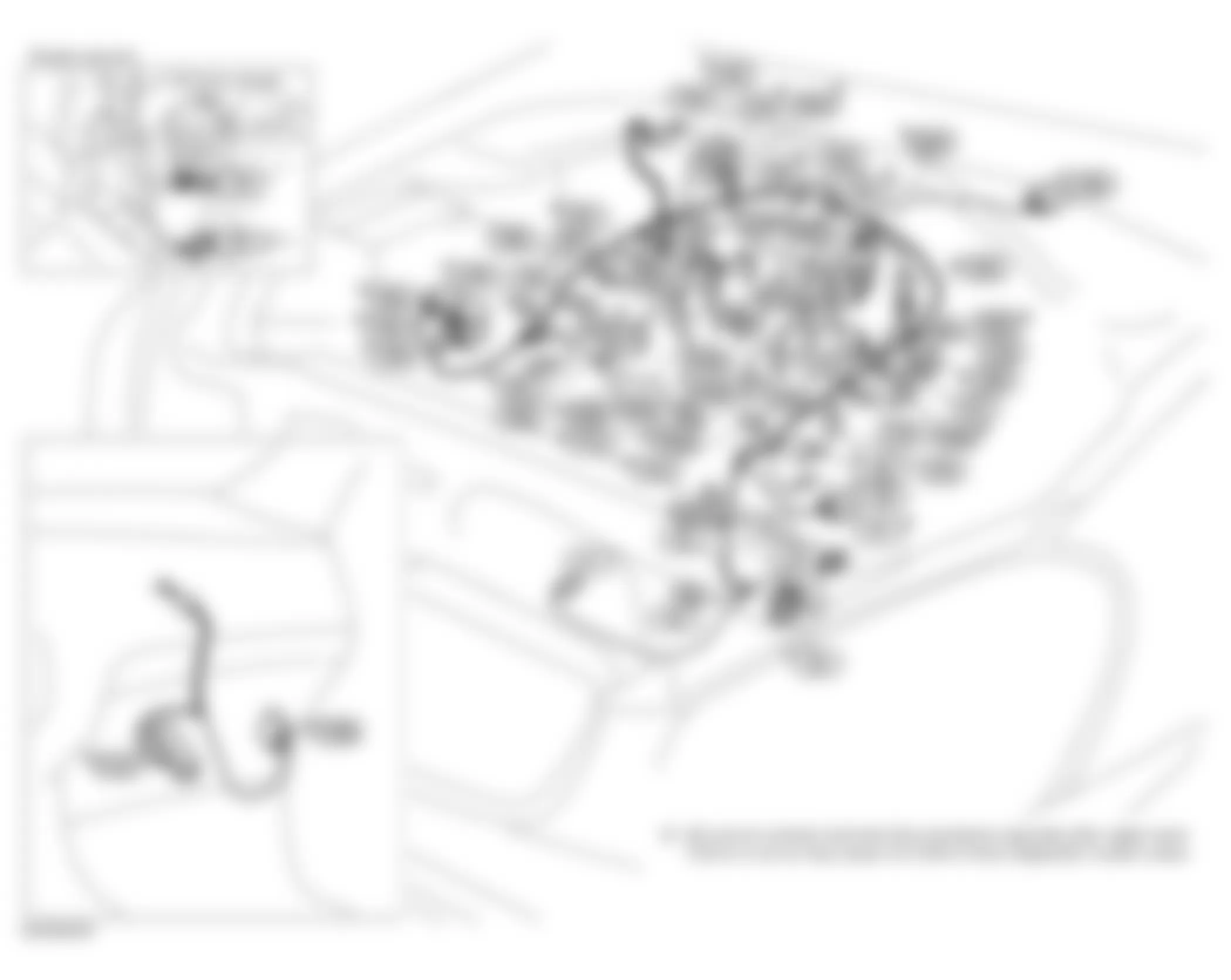
Fig. 6: Infiniti Q45 2005 - Component Locations - Vehicle Overview
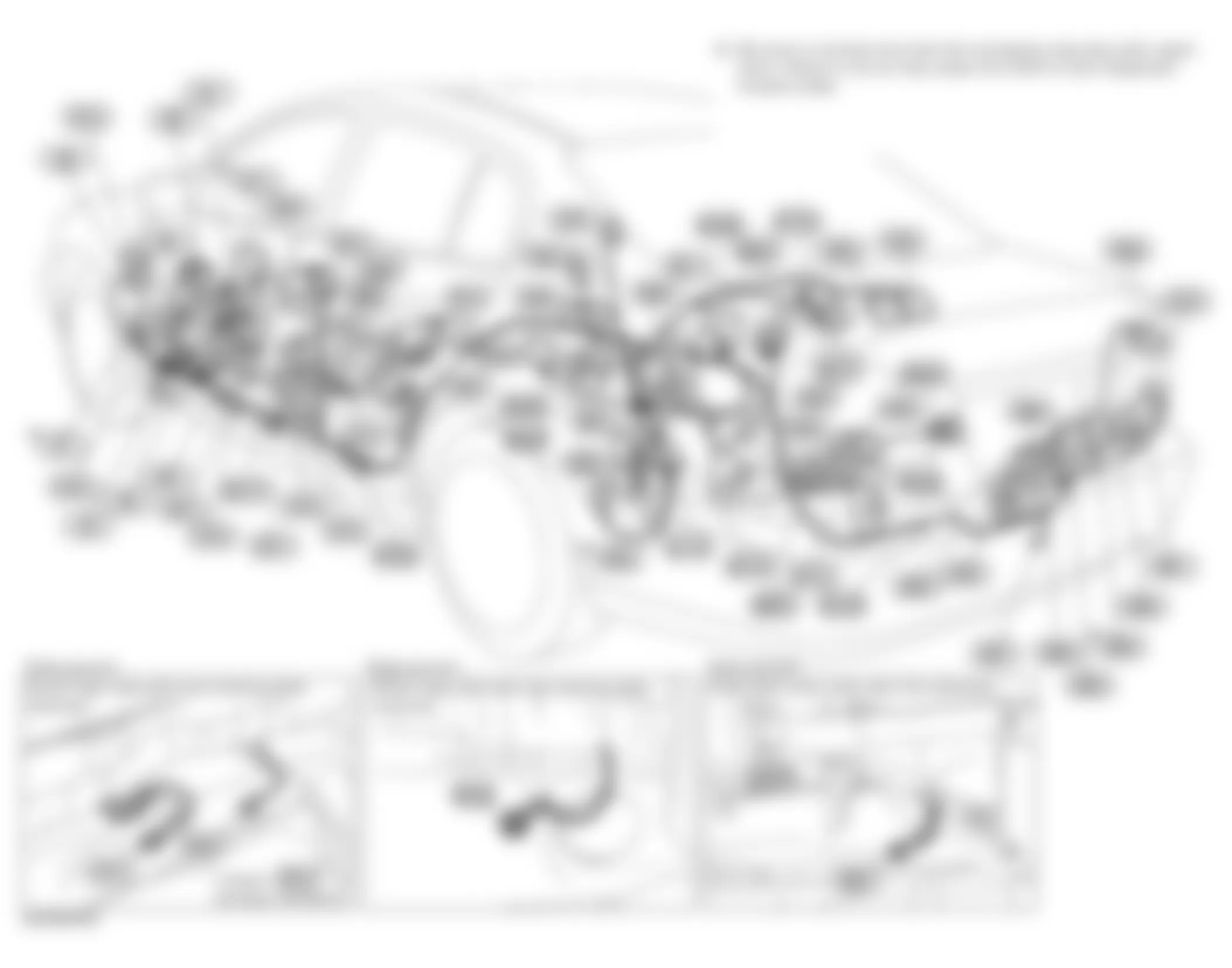
Fig. 7: Infiniti Q45 2005 - Component Locations - Vehicle Overview
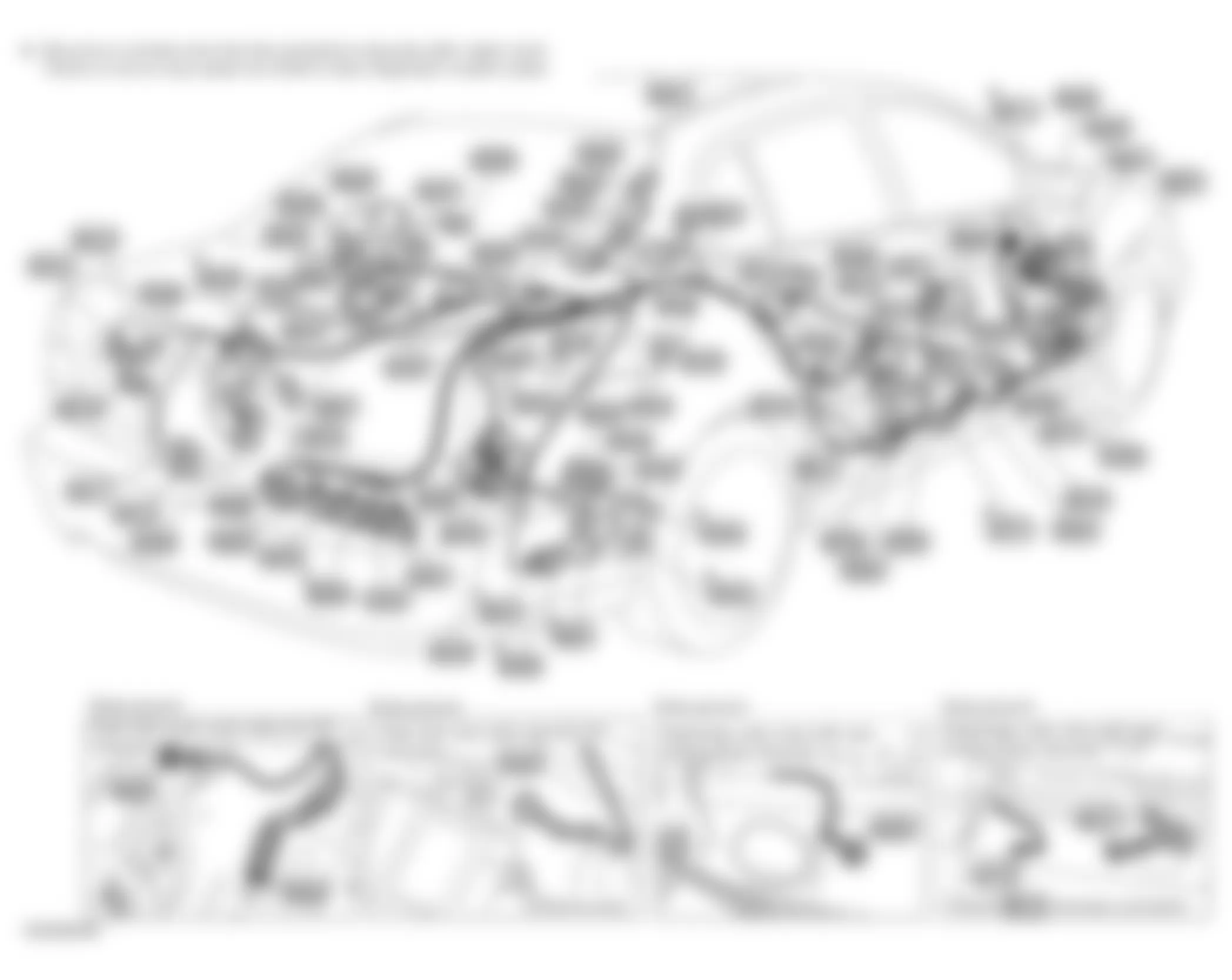
Fig. 8: Infiniti Q45 2005 - Component Locations - Vehicle Overview
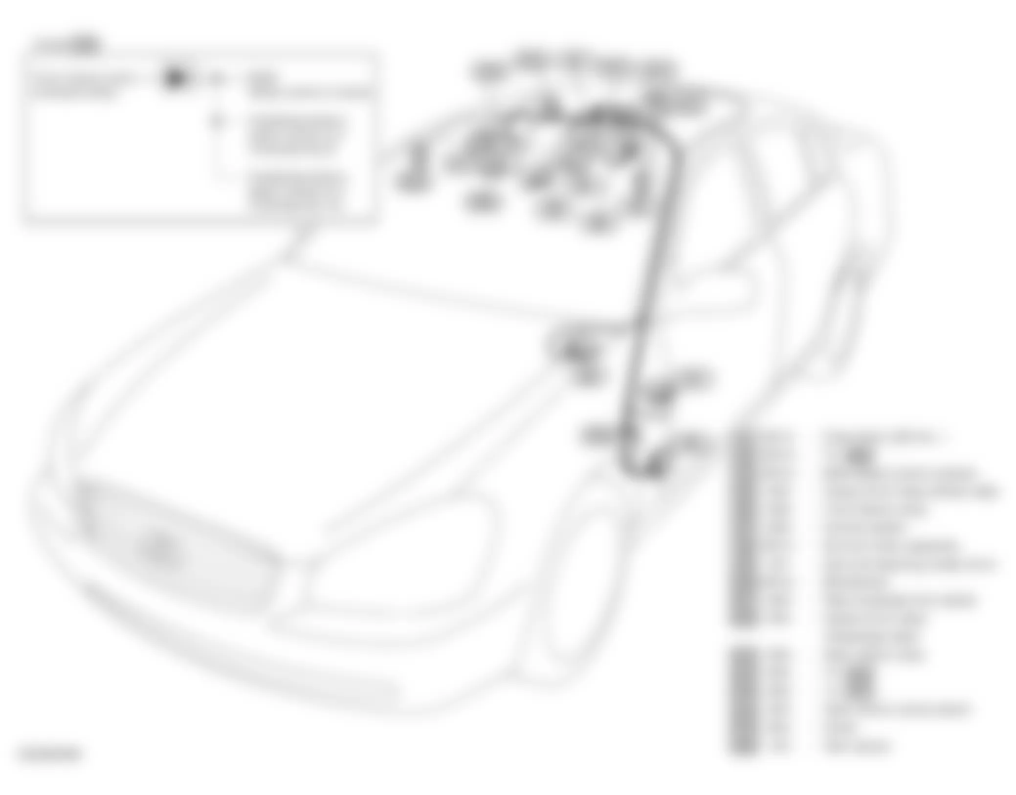
Fig. 9: Infiniti Q45 2005 - Component Locations - Left Front Door
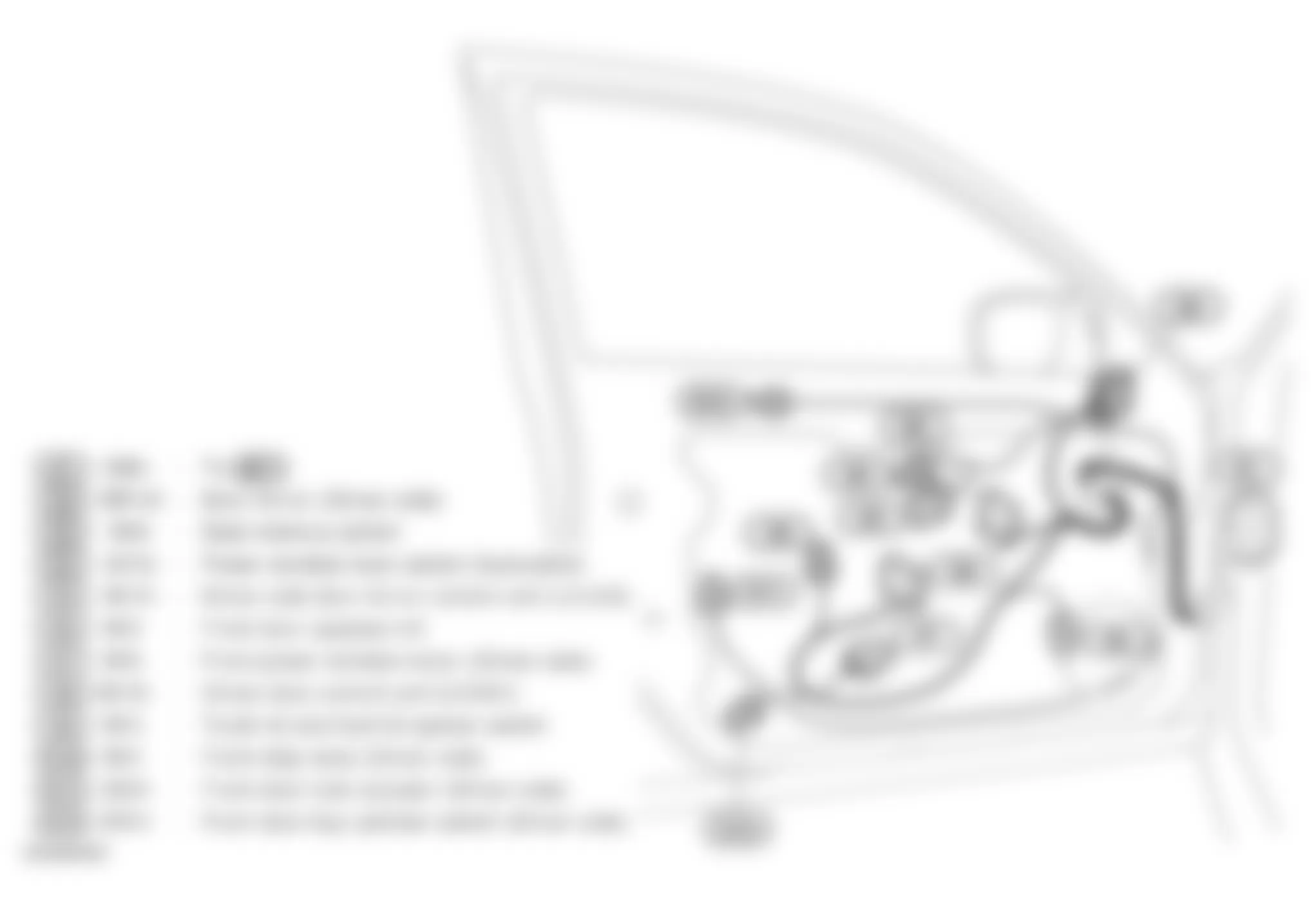
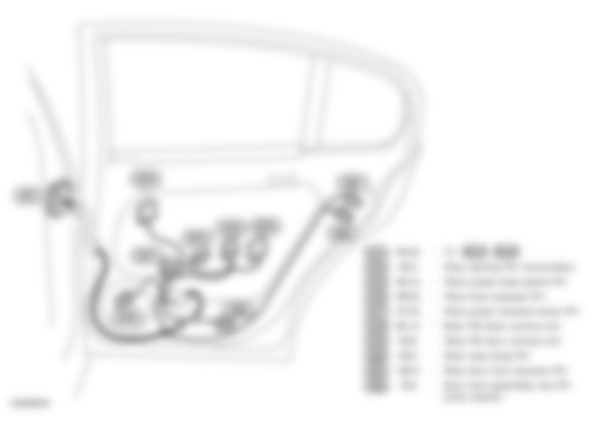
Fig. 10: Infiniti Q45 2005 - Component Locations - Left Rear Door
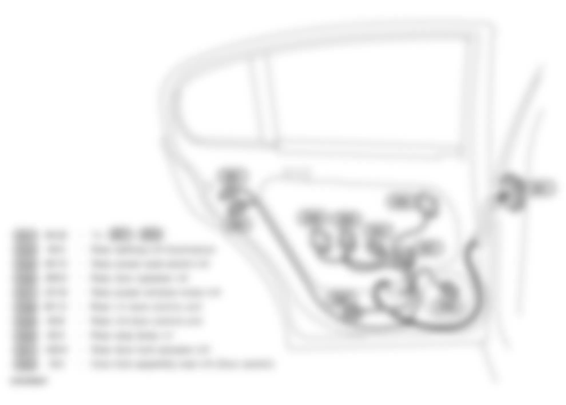
Fig. 11: Infiniti Q45 2005 - Component Locations - Vehicle Overview
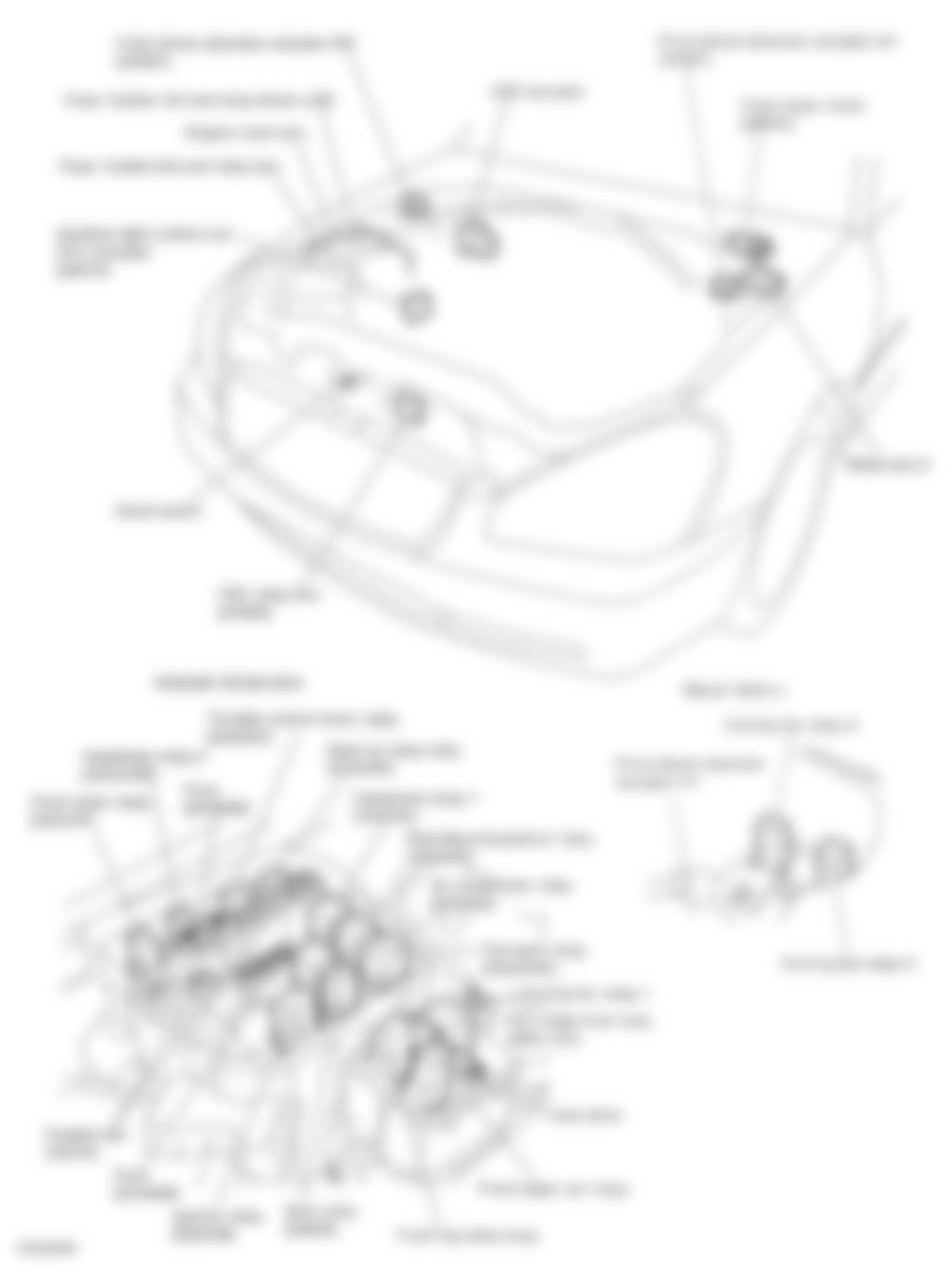
Fig. 12: Infiniti Q45 2005 - Component Locations - Vehicle Overview
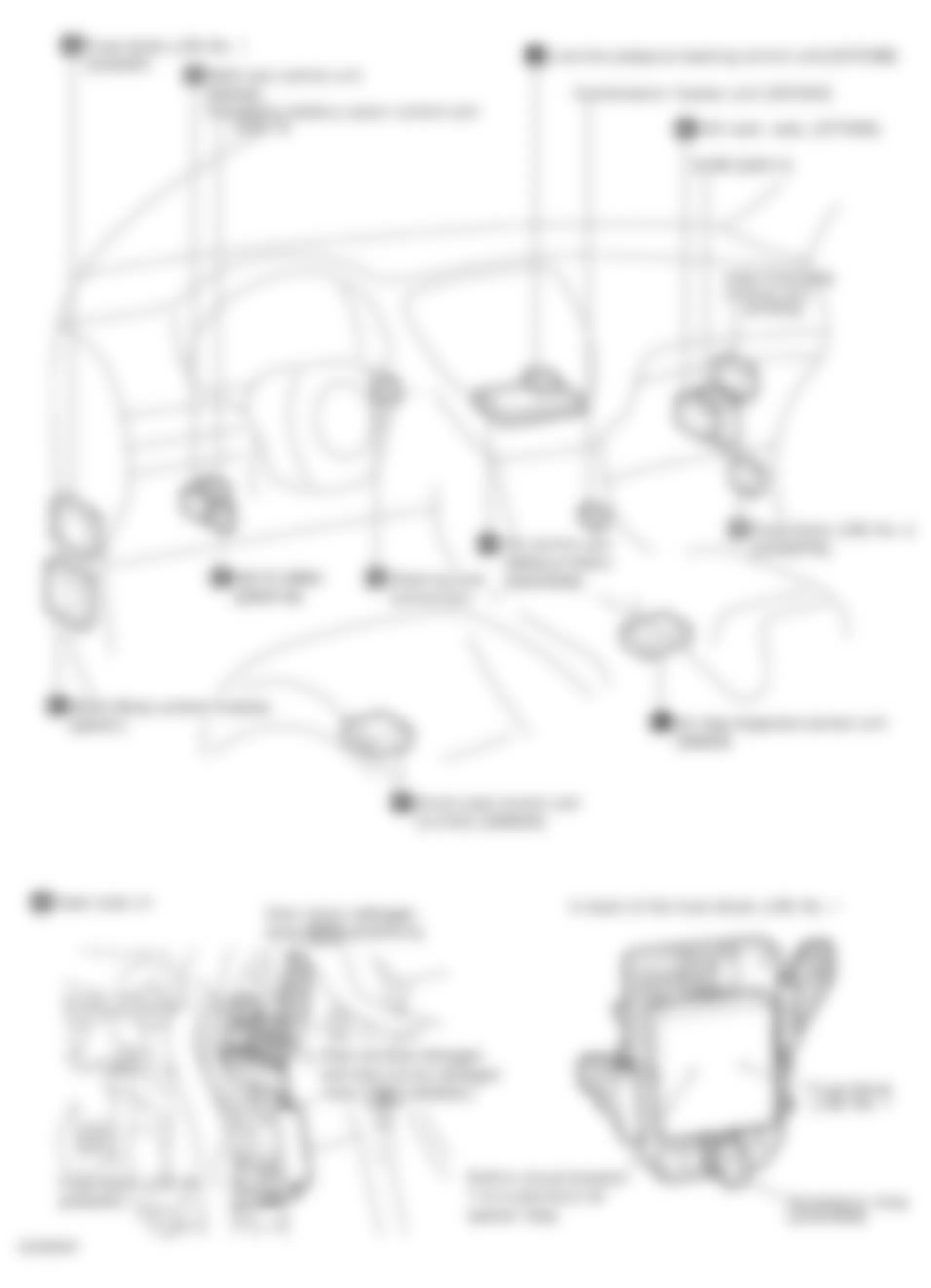
Fig. 13: Infiniti Q45 2005 - Component Locations - Vehicle Overview
Fig. 14: Infiniti Q45 2005 - Component Locations - Rear Seats
Fig. 15: Infiniti Q45 2005 - Component Locations - Rear Of Vehicle
Fig. 16: Infiniti Q45 2005 - Component Locations - Fuse Block (J/B) No. 1
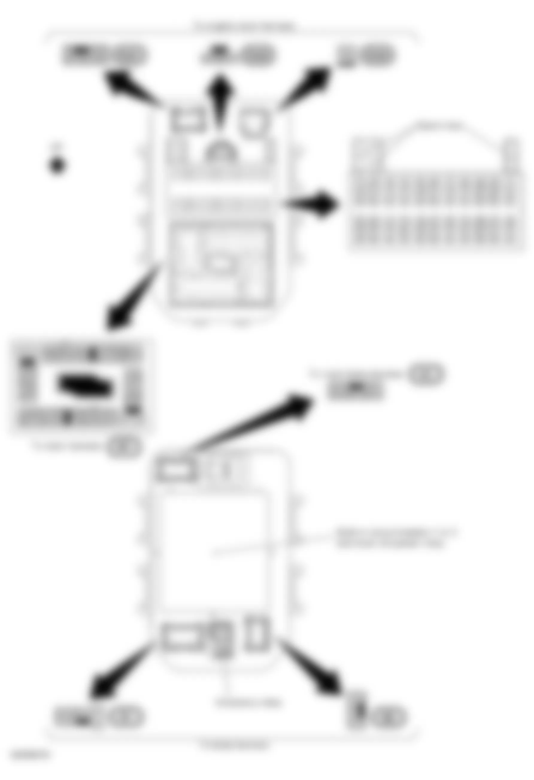
Fig. 17: Infiniti Q45 2005 - Component Locations - Fuse Block (J/B) No. 2
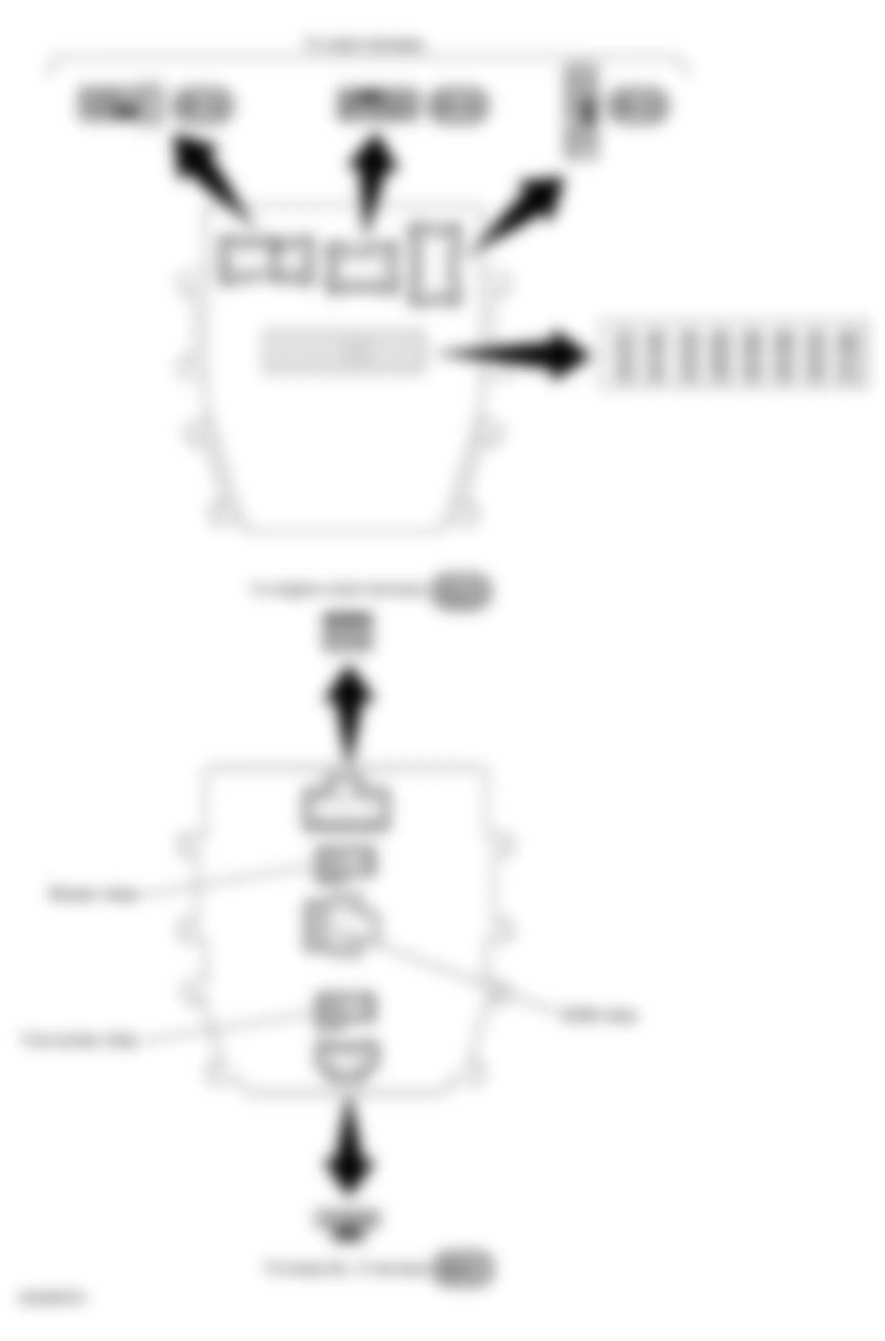
Fig. 18: Infiniti Q45 2005 - Component Locations - Fuse, Fusible Link & Relay Block (J/B)
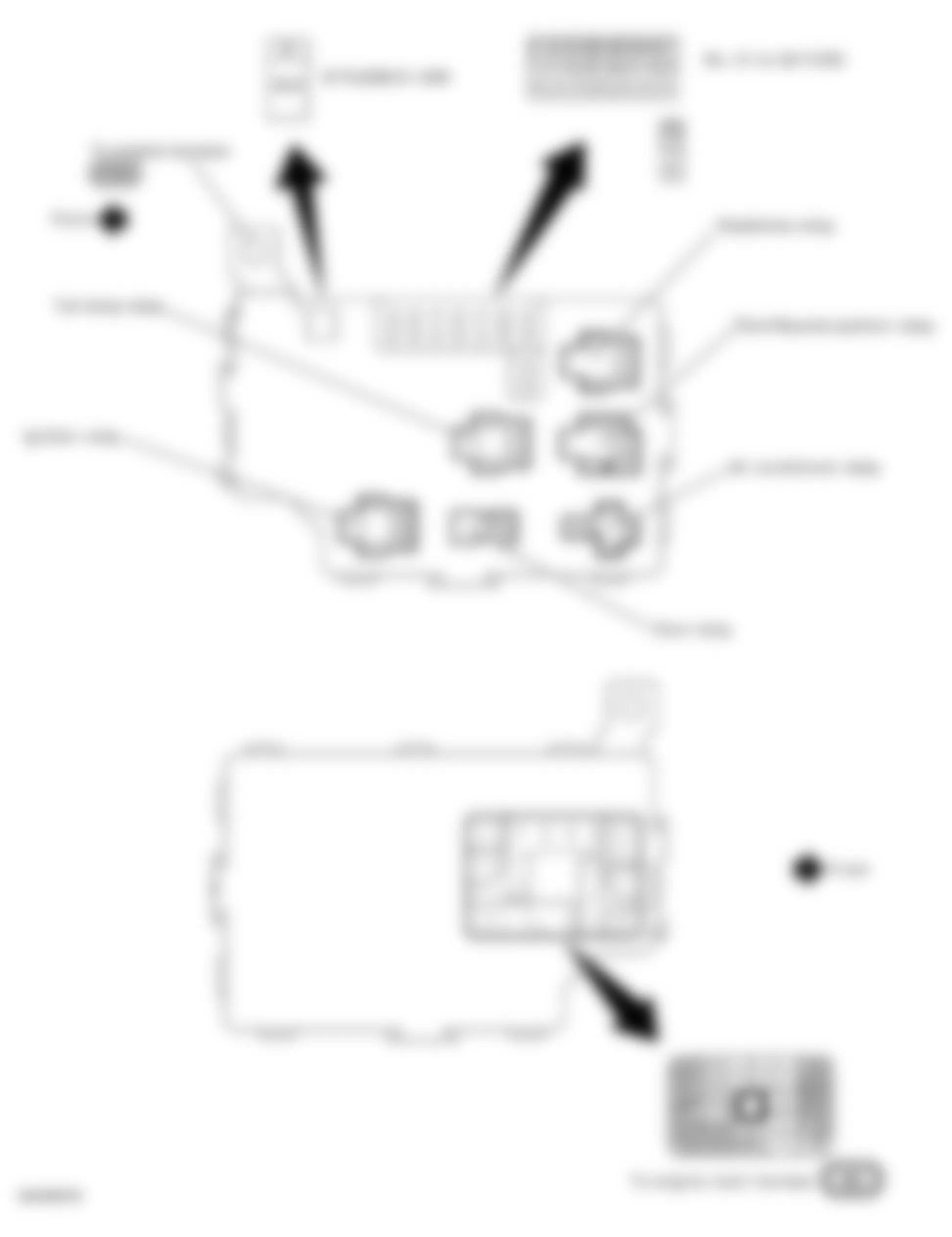
Fig. 19: Infiniti Q45 2005 - Component Locations - Fuse, Fusible Link & Relay Box
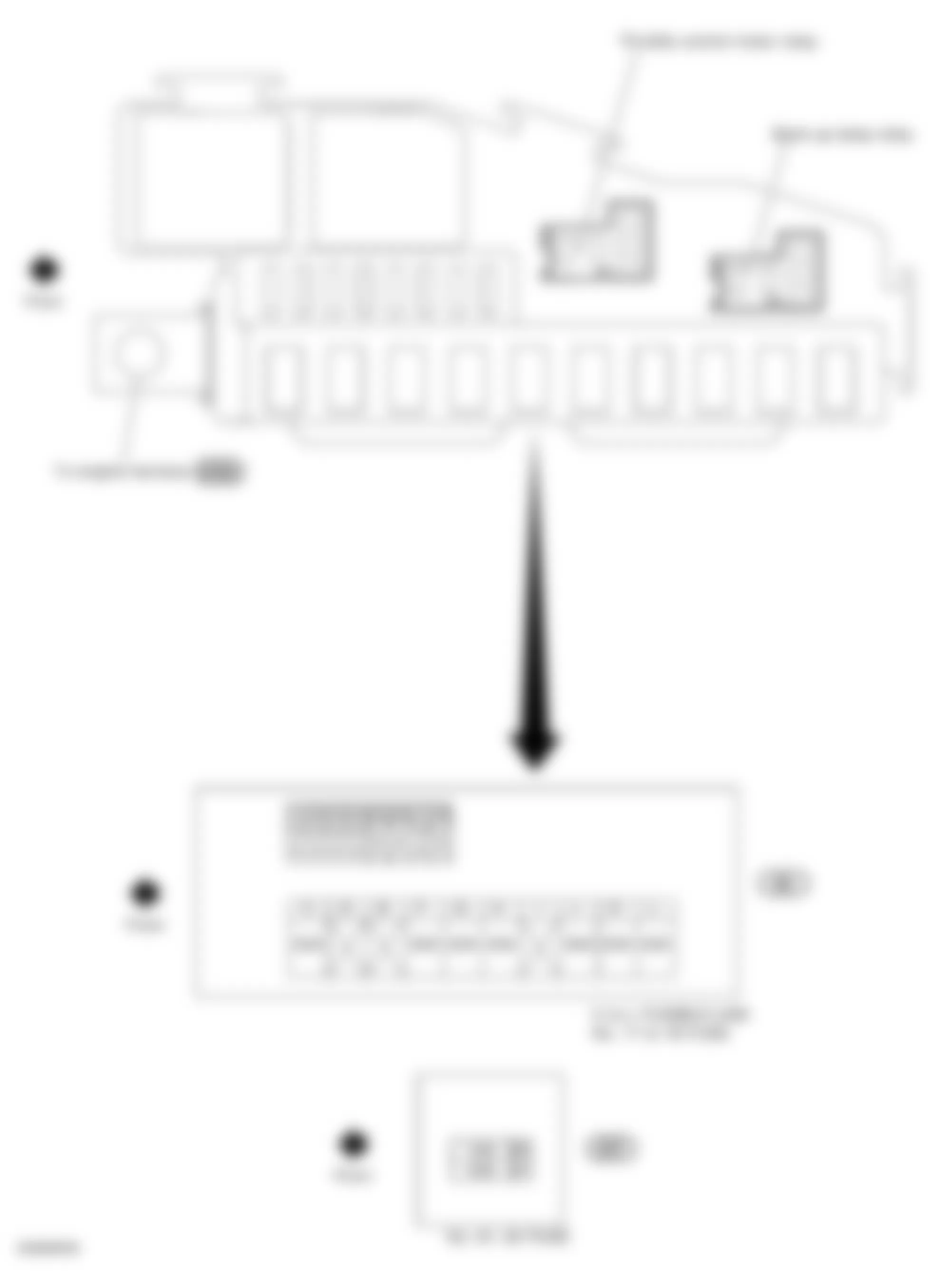
Fig. 20: Infiniti Q45 2005 - Component Locations - Right Front Door
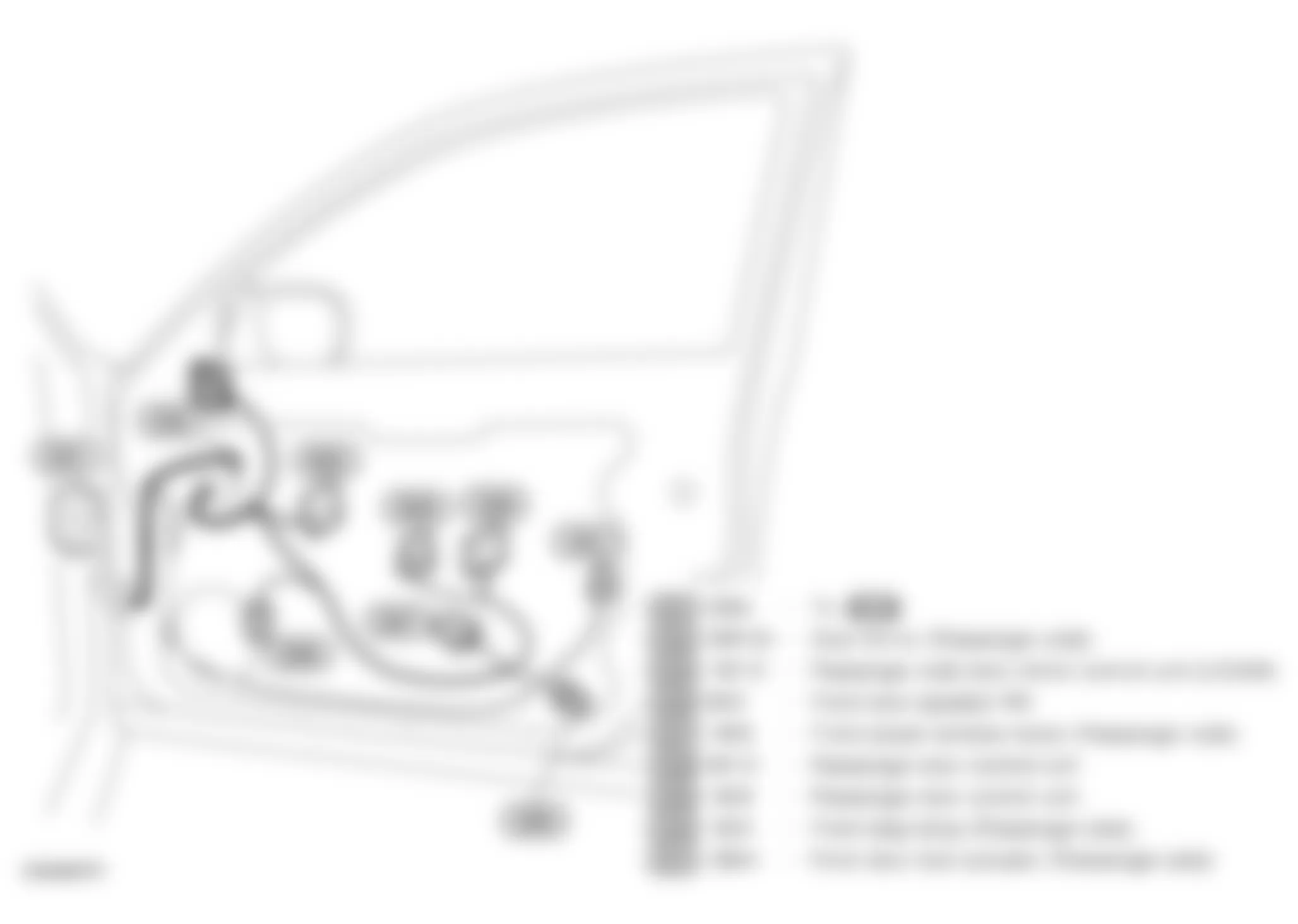
Fig. 21: Infiniti Q45 2005 - Component Locations - Right Rear Passenger's Door