2010 INFINITI FX35 & FX50
Infiniti FX35 2010 - BUZZERS, RELAYS & TIMERS
Infiniti FX35 2010 BUZZERS, RELAYS & TIMERS LOCATION
Component Location Accessory Relay In fuse block (J/B). See Fig. 15. Accessory Relay - 2 Right side of dash. See Fig. 1. Back-Up Lamp Relay (M69) Right side of dash. See Fig. 1. Blower Relay In fuse block (J/B). See Fig. 15. Buzzer (B231) Right "C" pillar. See Fig. 8. Climate Controlled Seat Relay (M64) Center of dash. See Fig. 1. Cooling Fan Relay 1 (E15) Right rear of engine compartment. See Fig. 2. Cooling Fan Relay 2 In fuse & fusible link block. See Fig. 16. Horn Relays 1 & 2 In fuse & fusible link block. See Fig. 16. ICC Brake Hold Relay In fuse & fusible link block. See Fig. 16. Ignition Relay In fuse block (J/B). See Fig. 15. Intelligent Key Warning Buzzer (Engine Room) (E80) Right front of engine compartment. See Fig. 2. Lane Departure Warning Buzzer (M45) Lower center of dash. See Fig. 1. RAS Motor Relay (B36) Left side of luggage compartment. See Fig. 7. Rear Window Defogger Relay In fuse block (J/B). See Fig. 15. Shift Lock Relay In fuse & fusible link block. See Fig. 16. Starter Control Relay In IPDM E/R (intelligent power distribution module engine room). See Fig. 17. VVEL Actuator Motor Relay (E90) Right rear of engine compartment. See Fig. 2.
Infiniti FX35 2010 - CIRCUIT PROTECTION DEVICES
Infiniti FX35 2010 CIRCUIT PROTECTION DEVICES LOCATION
Component Location Circuit Breaker (M62) Center of dash. See Fig. 1. Fuse Block (J/B) (M1) Left kick panel. See Fig. 1. Fuse & Fusible Link Block (E12) Right rear of engine compartment. See Fig. 2. Fusible Link Holder (E1) Right rear of engine compartment. See Fig. 2. IPDM E/R (Intelligent Power Distribution Module Engine Room) (E4) Right rear of engine compartment. See Fig. 2.
Infiniti FX35 2010 - CONTROL UNITS
Infiniti FX35 2010 CONTROL UNITS LOCATION
Component Location ABS Actuator & Electric Unit (Control Unit) (E41) Left rear of engine compartment. See Fig. 1. AFS Control Unit (M16) Left end of dash. See Fig. 1. Around View Monitor Control Unit (B46) Under driver's seat. See Fig. 7. Automatic Drive Positioner Control Unit (M52) Left center of dash. See Fig. 1. AWD Control Unit (M105) Right end of dash. See Fig. 1. Back Door Control Unit (D123) Lower left side of back door. See Fig. 14. BCM (Body Control Module) (3) Right end of dash. See Fig. 20. Brake Booster Control Unit (B251) Right side of luggage compartment. See Fig. 8. Camera Control Unit (B50) Under driver's seat. See Fig. 7. CAN Gateway (M125) Right end of dash. See Fig. 1. Cooling Fan Control Module-1 On cooling fan 1 assembly. See Fig. 23. Cooling Fan Control Module-2 On cooling fan 2 assembly. See Fig. 23. Cooling Fan Control Module Top center of radiator. See Fig. 22. ECM (Engine Control Module) (F101) Right end of dash. See Fig. 1. E-Suspension Control Unit (B38) Left side of luggage compartment. See Fig. 7. Fuel Pump Control Module (B31) Left "C" pillar. See Fig. 7. Low Tire Pressure Warning Control Unit (M96) Right side of dash. See Fig. 1. Occupant Detection System Control Unit (11) Under front passenger's seat. See Fig. 21. Power Steering Control Unit (M108) Right side of dash. See Fig. 1. Pre-Crash Seat Belt Control Unit (Driver Side) (1) Base of left "B" pillar. See Fig. 20. Pre-Crash Seat Belt Control Unit (Passenger Side) (2) Base of right "B" pillar. See Fig. 20. Remote Keyless Entry Receiver (M104) Right end of dash. See Fig. 1. Side Support Unit (Driver/Passenger) In respective front seat back. TCM (Transmission Control Module) On automatic transmission. Total Illumination Control Unit (M129) Right side of dash. See Fig. 1. VVEL Control Module Right rear of engine compartment. See Fig. 23.
Infiniti FX35 2010 - MOTORS
Infiniti FX35 2010 MOTORS LOCATION
Component Location Air Mix Door Motor (Driver Side) (4) Left side of dash. See Fig. 19. Air Mix Door Motor (Passenger Side) (2) Left side of HVAC unit. See Fig. 19. Back Door Lock Assembly (D122) Lower center of back door. See Fig. 14. Blower Motor (9) Lower right side of dash. See Fig. 19. Climate Controlled Seat Blower Motor (Driver/Passenger) Under respective front seat. Cooling Fan Motor-1 (3.5L) Behind left side of radiator. See Fig. 22. Cooling Fan Motor-1 (5.0L) Behind right side of radiator. See Fig. 23. Cooling Fan Motor-2 (3.5L) Behind right side of radiator. See Fig. 22. Cooling Fan Motor-2 (5.0L) Behind left side of radiator. See Fig. 23. Door Lock Assembly (Driver) (D15) Rear of driver's door. See Fig. 10. Door Lock Assembly (Left Rear) (D55) Rear of left rear door. See Fig. 12. Door Lock Assembly (Passenger) (D45) Rear of front passenger's door. See Fig. 11. Door Lock Assembly (Right Rear) (D75) Rear of right rear door. See Fig. 13. Door Mirror (Driver) (D3) Front of driver's door. See Fig. 10. Door Mirror (Passenger) (D33) Front of front passenger's door. See Fig. 11. Electric Throttle Control Actuator (Bank 1) (3.5L) Top right side of engine. See Fig. 22. Electric Throttle Control Actuator (Bank 1) (5.0L) Top left side of engine. See Fig. 23. Electric Throttle Control Actuator (Bank 2) (3.5L) Top left side of engine. See Fig. 22. Electric Throttle Control Actuator (Bank 2) (5.0L) Top right side of engine. See Fig. 23. Front & Rear Washer Pump Right front of engine compartment. Front Wiper Motor (E42) Left side of firewall. See Fig. 2. Fuel Level Sensor Unit & Fuel Pump (Main) (B22) In fuel tank. See Fig. 7. Fuel Lid Lock Actuator (B242) Right side of luggage compartment. See Fig. 8. Intake Door Motor (1) Right side of HVAC unit. See Fig. 19. Mode Door Motor (3) Left side of HVAC unit. See Fig. 19. Power Seat Front Lifting Motor (Driver/Passenger) Under respective front seat. Power Seat Lumbar Support Motor (Driver/Passenger) In respective front seat back. Power Seat Rear Lifting Motor (Driver/Passenger) Under respective front seat. Power Seat Reclining Motor (Driver/Passenger) In respective front seat back. Power Seat Sliding Motor (Driver/Passenger) Under respective front seat. Power Window Motor (Driver) (D10) Center of driver's door. See Fig. 10. Power Window Motor (Left Rear) (D52) Center of left rear door. See Fig. 12. Power Window Motor (Passenger) (D40) Center of front passenger's door. See Fig. 11. Power Window Motor (Right Rear) (D72) Center of right rear door. See Fig. 13. Rear Wiper Motor (D115) Center of back door. See Fig. 14. Sunroof Motor Assembly (R4) Center front of roof. See Fig. 9. VVEL Actuator Motor (Bank 1) Rear of left cylinder bank. See Fig. 23. VVEL Actuator Motor (Bank 2) Rear of right cylinder bank. See Fig. 23.
Infiniti FX35 2010 - SENDING UNITS & SENSORS
Infiniti FX35 2010 SENDING UNITS & SENSORS LOCATION
Component Location Accelerator Pedal Position Sensor Integral to accelerator pedal assembly. Air Bag Diagnosis Sensor Unit (8) Under rear of center console. See Fig. 21. Air Fuel Ratio (A/F) Sensor 1 (Bank 1) (3.5L) (F3) Rear of right cylinder bank. See Fig. 4. Air Fuel Ratio (A/F) Sensor 1 (Bank 1) (5.0L) (F67) Right rear of engine. See Fig. 6. Air Fuel Ratio (A/F) Sensor 1 (Bank 2) (3.5L) (F20) Rear of left cylinder bank. See Fig. 4. Air Fuel Ratio (A/F) Sensor 1 (Bank 2) (5.0L) (F66) Left rear of engine. See Fig. 6. Ambient Sensor (3) Behind center of front grille. See Fig. 18. Battery Current Sensor (3.5L) On battery. See Fig. 22. Battery Current Sensor (5.0L) On battery. See Fig. 23. Brake Booster Pressure Sensor On brake booster assembly. See Fig. 23. Brake Pedal Stroke Sensor (7) On brake pedal bracket. See Fig. 20. Brake Pressure Sensor (E45) Left rear of engine compartment. See Fig. 2. Camshaft Position Sensor (Bank 1) (3.5L) Rear of right cylinder bank. See Fig. 22. Camshaft Position Sensor (Bank 1) (5.0L) Front of left cylinder bank. See Fig. 23. Camshaft Position Sensor (Bank 2) (3.5L) Rear of left cylinder bank. See Fig. 22. Camshaft Position Sensor (Bank 2) (5.0L) Front of right cylinder bank. See Fig. 23. Crankshaft Position Sensor (3.5L) Lower right rear of engine. See Fig. 22. Crankshaft Position Sensor (5.0L) Lower rear of engine. See Fig. 23. Crash Zone Sensor (10) Behind center of front grille. See Fig. 21. Engine Coolant Temperature Sensor (3.5L) Rear of engine. See Fig. 22. Engine Coolant Temperature Sensor (5.0L) Right rear of engine. See Fig. 23. Exhaust Valve Timing Control Position Sensor (Bank 1) (3.5L) Rear of right cylinder bank. See Fig. 22. Exhaust Valve Timing Control Position Sensor (Bank 1) (5.0L) Front of left cylinder bank. See Fig. 23. Exhaust Valve Timing Control Position Sensor (Bank 2) (3.5L) Rear of left cylinder bank. See Fig. 22. Exhaust Valve Timing Control Position Sensor (Bank 2) (5.0L) Front of right cylinder bank. See Fig. 23. Gas Sensor (1) Behind center of front grille. See Fig. 18. Heated Oxygen Sensor 2 (Bank 1) (3.5L) (F54) Left front of engine. See Fig. 4. Heated Oxygen Sensor 2 (Bank 1) (5.0L) (F87) Left front of engine. See Fig. 6. Heated Oxygen Sensor 2 (Bank 2) (3.5L) (F53) Left front of engine. See Fig. 4. Heated Oxygen Sensor 2 (Bank 2) (5.0L) (F88) Right front of engine. See Fig. 6. ICC Sensor Integrated Unit (6) Lower left front of engine compartment. See Fig. 20. Intake Air Temperature Sensor (Bank 1) (3.5L) In right intake air duct. See Fig. 22. Intake Air Temperature Sensor (Bank 1) (5.0L) In left intake air duct. See Fig. 23. Intake Air Temperature Sensor (Bank 2) (3.5L) In left intake air duct. See Fig. 22. Intake Air Temperature Sensor (Bank 2) (5.0L) In right air intake duct. See Fig. 23. Intake Sensor (8) Lower right center of dash. See Fig. 19. In-Vehicle Sensor (6) Left side of dash. See Fig. 19. Knock Sensor (Bank 1) (3.5L) Top center of right cylinder bank. See Fig. 22. Knock Sensor (Bank 1) (5.0L) Top center of left cylinder bank. See Fig. 23. Knock Sensor (Bank 2) (3.5L) Top center of left cylinder bank. See Fig. 22. Knock Sensor (Bank 2) (5.0L) Top center of right cylinder bank. See Fig. 23. Manifold Absolute Pressure Sensor Top center of engine. See Fig. 23. Mass Air Flow Sensor (Bank 1) (3.5L) (F31) Right front of engine compartment. See Fig. 4. Mass Air Flow Sensor (Bank 1) (5.0L) (F86) Left front of engine compartment. See Fig. 6. Mass Air Flow Sensor (Bank 2) (3.5L) (F41) Left front of engine compartment. See Fig. 4. Mass Air Flow Sensor (Bank 2) (5.0L) (F85) Right front of engine compartment. See Fig. 6. Occupant Detection System Seat Sensors (12) Under front passenger's seat. See Fig. 21. Rain Sensor (R9) Center front of roof. See Fig. 9. Refrigerant Pressure Sensor (2) Center front of engine compartment. See Fig. 18. Steering Angle Sensor (5) On steering column. See Fig. 20. Sunload Sensor (5) Top left side of dash. See Fig. 19. VVEL Control Shaft Position Sensor (Bank 1) Rear of left cylinder bank. See Fig. 23. VVEL Control Shaft Position Sensor (Bank 2) Rear of right cylinder bank. See Fig. 23. Yaw Rate/Side G Sensor (M143) Under rear of center console. See Fig. 1.
Infiniti FX35 2010 - SOLENOIDS & SOLENOID VALVES
Infiniti FX35 2010 SOLENOIDS & SOLENOID VALVES LOCATION
Component Location Compressor (Magnet Clutch) (4) Left front of engine. See Fig. 18. EVAP Canister Vent Control Valve (B253) Under right rear of vehicle. See Fig. 8. Exhaust Valve Timing Control Solenoid Valve (Bank 1) Front of left cylinder bank. See Fig. 23. Exhaust Valve Timing Control Solenoid Valve (Bank 2) Front of right cylinder bank. See Fig. 23. Fuel Injector No. 1 (3.5L) (F21) Top of right cylinder bank. See Fig. 4. Fuel Injector No. 1 (5.0L) (F123) Top of left cylinder bank. See Fig. 6. Fuel Injector No. 2 (3.5L) (F22) Top of left cylinder bank. See Fig. 4. Fuel Injector No. 2 (5.0L) (F124) Top of right cylinder bank. See Fig. 6. Fuel Injector No. 3 (3.5L) (F23) Top of right cylinder bank. See Fig. 4. Fuel Injector No. 3 (5.0L) (F125) Top of left cylinder bank. See Fig. 6. Fuel Injector No. 4 (3.5L) (F24) Top of left cylinder bank. See Fig. 4. Fuel Injector No. 4 (5.0L) (F126) Top of right cylinder bank. See Fig. 6. Fuel Injector No. 5 (3.5L) (F25) Top of right cylinder bank. See Fig. 4. Fuel Injector No. 5 (5.0L) (F127) Top of left cylinder bank. See Fig. 6. Fuel Injector No. 6 (3.5L) (F26) Top of left cylinder bank. See Fig. 4. Fuel Injector No. 6 (5.0L) (F128) Top of right cylinder bank. See Fig. 6. Fuel Injector No. 7 (F129) Top of left cylinder bank. See Fig. 6. Fuel Injector No. 8 (F130) Top of right cylinder bank. See Fig. 6. Intake Valve Timing Control Solenoid Valve (Bank 1) (3.5L) (F28) Front of right cylinder bank. See Fig. 4. Intake Valve Timing Control Solenoid Valve (Bank 1) (5.0L) (F47) Front of left cylinder bank. See Fig. 6. Intake Valve Timing Control Solenoid Valve (Bank 2) (3.5L) (F29) Front of left cylinder bank. See Fig. 4. Intake Valve Timing Control Solenoid Valve (Bank 2) (5.0L) (F61) Front of right cylinder bank. See Fig. 6. Steering Lock Unit (M40) On steering column. See Fig. 1.
Infiniti FX35 2010 - SWITCHES
Infiniti FX35 2010 SWITCHES LOCATION
Component Location ASCD Brake Switch (E109) On brake pedal bracket. See Fig. 3. Front Door Switch (Driver) (B16) Left "B" pillar. See Fig. 7. Front Door Switch (Passenger) (B216) Right "B" pillar. See Fig. 8. Hood Switch (E30) Right front of engine compartment. See Fig. 2. ICC Brake Switch (E114) On brake pedal bracket. See Fig. 3. Rear Door Switch (Left) (B23) Left "C" pillar. See Fig. 7. Rear Door Switch (Right) (B223) Right "C" pillar. See Fig. 8. Seat Belt Buckle Switch (Driver) (8) In driver's seat belt buckle assembly. See Fig. 20. Seat Belt Buckle Switch (Passenger) (9) In front passenger's seat belt buckle assembly. See Fig. 20. Stop Lamp Switch (E110) On brake pedal bracket. See Fig. 3.
Infiniti FX35 2010 - MISCELLANEOUS
Infiniti FX35 2010 MISCELLANEOUS LOCATION
Component Location Accelerator Pedal Actuator (E115) Left side of dash. See Fig. 3. Air Bag Module (Driver) (2) In steering wheel. See Fig. 21. Air Bag Module (Front Passenger) (3) Right side of dash. See Fig. 21. Alternator (3.5L) (F36) Right front of engine. See Fig. 4. Alternator (5.0L) (F36) Right front of engine. See Fig. 6. A/T Assembly (3.5L) (F51) On transmission. See Fig. 4. A/T Assembly (5.0L) (F51) On transmission. See Fig. 6. BOSE Amplifier (B42) Left rear of luggage compartment. See Fig. 7. Brake Booster (E44) Left rear corner of engine compartment. See Fig. 2. Compressor (ECV) (5) Left front of engine. See Fig. 18. Condenser (3.5L) (F8) Top right side of engine. See Fig. 4. Condenser (5.0L) (F43) Left front of engine compartment. See Fig. 6. Data Link Connector (M24) Left side of dash. See Fig. 1. Exhaust Valve Timing Control Magnet Retarder (Bank 1) (3.5L) Front of right cylinder bank. See Fig. 22. Exhaust Valve Timing Control Magnet Retarder (Bank 2) (3.5L) Front of left cylinder bank. See Fig. 22. Horn (High) (E69) Behind left side of front grille. See Fig. 2. Horn (Low) (E61) Behind right side of front grille. See Fig. 2. ICC Warning Chime (M17) Left end of dash. See Fig. 1. Ignition Coil No. 1 (W/Power Transistor) (3.5L) (F11) Top of right cylinder bank. See Fig. 4. Ignition Coil No. 1 (W/Power Transistor) (5.0L) (F75) Top of left cylinder bank. See Fig. 6. Ignition Coil No. 2 (W/Power Transistor) (3.5L) (F12) Top of left cylinder bank. See Fig. 4. Ignition Coil No. 2 (W/Power Transistor) (5.0L) (F76) Top of right cylinder bank. See Fig. 6. Ignition Coil No. 3 (W/Power Transistor) (3.5L) (F13) Top of right cylinder bank. See Fig. 4. Ignition Coil No. 3 (W/Power Transistor) (5.0L) (F77) Top of left cylinder bank. See Fig. 6. Ignition Coil No. 4 (W/Power Transistor) (3.5L) (F14) Top of left cylinder bank. See Fig. 4. Ignition Coil No. 4 (W/Power Transistor) (5.0L) (F78) Top of right cylinder bank. See Fig. 6. Ignition Coil No. 5 (W/Power Transistor) (3.5L) (F15) Top of right cylinder bank. See Fig. 4. Ignition Coil No. 5 (W/Power Transistor) (5.0L) (F79) Top of left cylinder bank. See Fig. 6. Ignition Coil No. 6 (W/Power Transistor) (3.5L) (F16) Top of left cylinder bank. See Fig. 4. Ignition Coil No. 6 (W/Power Transistor) (5.0L) (F80) Top of right cylinder bank. See Fig. 6. Ignition Coil No. 7 (W/Power Transistor) (F81) Top of left cylinder bank. See Fig. 6. Ignition Coil No. 8 (W/Power Transistor) (F82) Top of right cylinder bank. See Fig. 6. Inside Key Antenna (Console) (M146) Under center console. See Fig. 1. Inside Key Antenna (Instrument Center) (M131) Center of dash. See Fig. 1. Inside Key Antenna (Luggage Room) (B228) Center front of luggage compartment. See Fig. 8. Ionizer (M57) Left side of dash. See Fig. 1. Lane Camera Unit (R8) Center front of roof. See Fig. 9. Option Connector (B59) Left "C" pillar. See Fig. 7. Outside Key Antenna (Back Door) (D118) Lower right side of back door. See Fig. 14. Outside Key Antenna (Left/Right Front) Integral to respective front door handle assembly. Satellite Radio Tuner (B236) Right rear of luggage compartment. See Fig. 8. Side Air Bag Curtain Module (Left/Right) (9) In respective roof rails. See Fig. 21. Side Air Bag Module (Left/Right Front) (4) In respective outer side of front seat backs. See Fig. 21. TEL Adapter Unit (B237) Right rear of luggage compartment. See Fig. 8. Unified Meter & A/C Amplifier (7) Center of dash. See Fig. 19. Video Distributor (M99) Right side of dash. See Fig. 1.
Infiniti FX35 2010 - CONNECTORS
Infiniti FX35 2010 CONNECTORS LOCATION
Component Location B1 (White, 100 Pin) Left kick panel. See Fig. 7. B2 (White, 16 Pin) Left kick panel. See Fig. 7. B3 (White, 2 Pin) Left kick panel. See Fig. 7. B4 (White, 12 Pin) Left kick panel. See Fig. 7. B5 (White, 40 Pin) Left kick panel. See Fig. 7. B8 (Brown, 12 Pin) Left kick panel. See Fig. 7. B11 (White, 16 Pin) Under driver's seat. See Fig. 7. B14 (White, 12 Pin) Under center console. See Fig. 7. B27 (White, 6 Pin) Top of left "C" pillar. See Fig. 7. B28 (White, 24 Pin) Top of left "C" pillar. See Fig. 7. B66 (White, 60 Pin) Left rear of luggage compartment. See Fig. 7. B67 (White, 8 Pin) Left rear of luggage compartment. See Fig. 7. B201 (White, 100 Pin) Right kick panel. See Fig. 8. B241 (White, 8 Pin) Center rear of luggage compartment. See Fig. 8. B243 (White, 40 Pin) Center rear of luggage compartment. See Fig. 8. D1 (White, 55 Pin) Left kick panel. See Fig. 10. D31 (White, 55 Pin) Right kick panel. See Fig. 11. D51 (White, 18 Pin) Left "B" pillar. See Fig. 12. D71 (White, 18 Pin) Right "B" pillar. See Fig. 13. D101 (White, 6 Pin) Top of left "C" pillar. See Fig. 14. D102 (White, 24 Pin) Top of left "C" pillar. See Fig. 14. E3 (Black, 48 Pin) Right rear of engine compartment. See Fig. 2. E10 (Black, 52 Pin) Right rear of engine compartment. See Fig. 2. E66 (Black, 8 Pin) Behind left side of front fascia. See Fig. 2. E104 (White, 12 Pin) Left end of dash. See Fig. 3. E106 (White, 100 Pin) Left end of dash. See Fig. 3. E121 (White, 2 Pin) Left end of dash. See Fig. 3. E122 (Brown, 12 Pin) Left end of dash. See Fig. 3. E151 (Black, 8 Pin) Behind left side of front fascia. See Fig. 2. F1 (3.5L) (Black, 48 Pin) Right rear of engine compartment. See Fig. 4. F10 (Black, 52 Pin) Right rear of engine compartment. See Fig. 6. F60 (Black, 6 Pin) Left side of engine. See Fig. 6. F69 (Black, 6 Pin) Right rear of engine. See Fig. 6. F103 (White, 46 Pin) Right end of dash. See Fig. 5. F104 (White, 8 Pin) Right end of dash. See Fig. 5. F105 (White, 8 Pin) Right end of dash. See Fig. 5. F121 (Black, 6 Pin) Left side of engine. See Fig. 6. F122 (Black, 6 Pin) Right rear of engine. See Fig. 6. M4 (White, 40 Pin) Left kick panel. See Fig. 1. M5 (White, 55 Pin) Left kick panel. See Fig. 1. M6 (White, 100 Pin) Left end of dash. See Fig. 1. M7 (White, 100 Pin) Left end of dash. See Fig. 1. M25 (White, 16 Pin) Left end of dash. See Fig. 1. M106 (White, 18 Pin) Left end of dash. See Fig. 1. M110 (White, 16 Pin) Left end of dash. See Fig. 1. M116 (White, 100 Pin) Right end of dash. See Fig. 1. M117 (White, 100 Pin) Right end of dash. See Fig. 1. M124 (White, 55 Pin) Right end of dash. See Fig. 1. M139 (White, 32 Pin) Under center console. See Fig. 1. M144 (White, 12 Pin) Under center console. See Fig. 1. M181 (White, 32 Pin) Under center console. See Fig. 1. R1 (White, 18 Pin) Base of left "A" pillar. See Fig. 9. R2 (White, 24 Pin) Left front of roof. See Fig. 9. R7 (White, 16 Pin) Base of left "A" pillar. See Fig. 9. R11 (White, 24 Pin) Left front of roof. See Fig. 9.
Infiniti FX35 2010 - GROUNDS
Infiniti FX35 2010 GROUNDS LOCATION
Component Location B7 Left kick panel. See Fig. 7. B17 Left "B" pillar. See Fig. 7. B24 Left "C" pillar. See Fig. 7. B61 Left side of luggage compartment. See Fig. 7. B62 Left rear of luggage compartment. See Fig. 7. B63 Behind rear seat. See Fig. 7. B202 Right kick panel. See Fig. 8. B217 Right "B" pillar. See Fig. 8. B224 Right "C" pillar. See Fig. 8. D103 Center rear of roof. See Fig. 14. D124 Top of left "C" pillar. See Fig. 14. E22 Right side of engine compartment. See Fig. 2. E23 Right side of engine compartment. See Fig. 2. E43 Left rear of engine compartment. See Fig. 2. E46 Left rear of engine compartment. See Fig. 2. F33 (3.5L) Right front of engine. See Fig. 4. F33 (5.0L) Left front of engine. See Fig. 6. F34 (3.5L) Right front of engine. See Fig. 4. F34 (5.0L) Left front of engine. See Fig. 6. M11 Left end of dash. See Fig. 1. M55 Left side of dash. See Fig. 1. M95 Right side of dash. See Fig. 1.
Infiniti FX35 2010 - COMPONENT LOCATION GRAPHICS
NOTE:
Fig.res may show multiple component locations. - appropriate table for proper figure references.

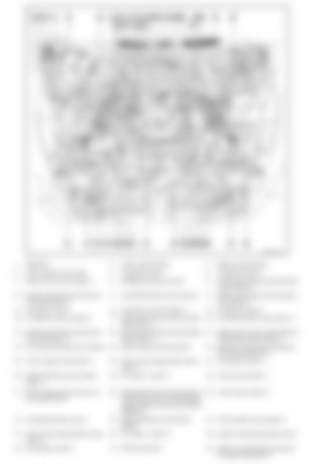
Fig. 1: Infiniti FX35 2010 - Component Locations - Dash & Center Console
Fig. 2: Infiniti FX35 2010 - Component Locations - Engine Compartment
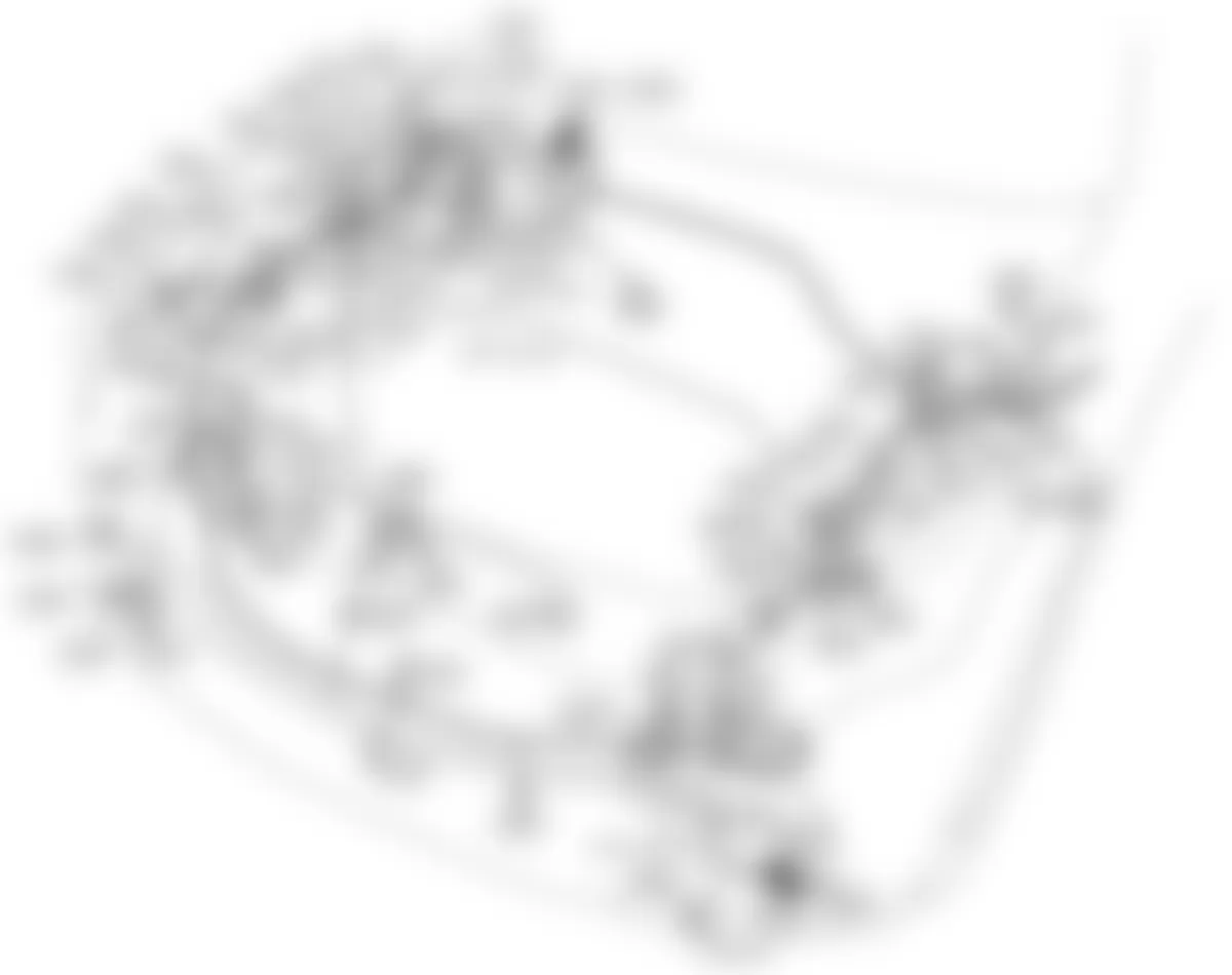
Fig. 3: Infiniti FX35 2010 - Component Locations - Left Side Of Dash

Fig. 4: Infiniti FX35 2010 - Component Locations - Engine (3.5L)

Fig. 5: Infiniti FX35 2010 - Component Locations - Right Side Of Dash

Fig. 6: Infiniti FX35 2010 - Component Locations - Engine (5.0L)

Fig. 7: Infiniti FX35 2010 - Component Locations - Left Side & Rear Of Vehicle

Fig. 8: Infiniti FX35 2010 - Component Locations - Right Side Of Vehicle

Fig. 9: Infiniti FX35 2010 - Component Locations - Roof

Fig. 10: Infiniti FX35 2010 - Component Locations - Driver's Door

Fig. 11: Infiniti FX35 2010 - Component Locations - Front Passenger's Door

Fig. 12: Infiniti FX35 2010 - Component Locations - Left Rear Door
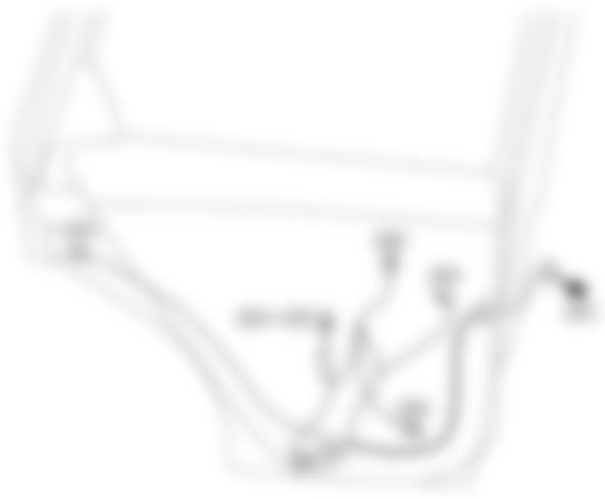
Fig. 13: Infiniti FX35 2010 - Component Locations - Right Rear Door

Fig. 14: Infiniti FX35 2010 - Component Locations - Back Door
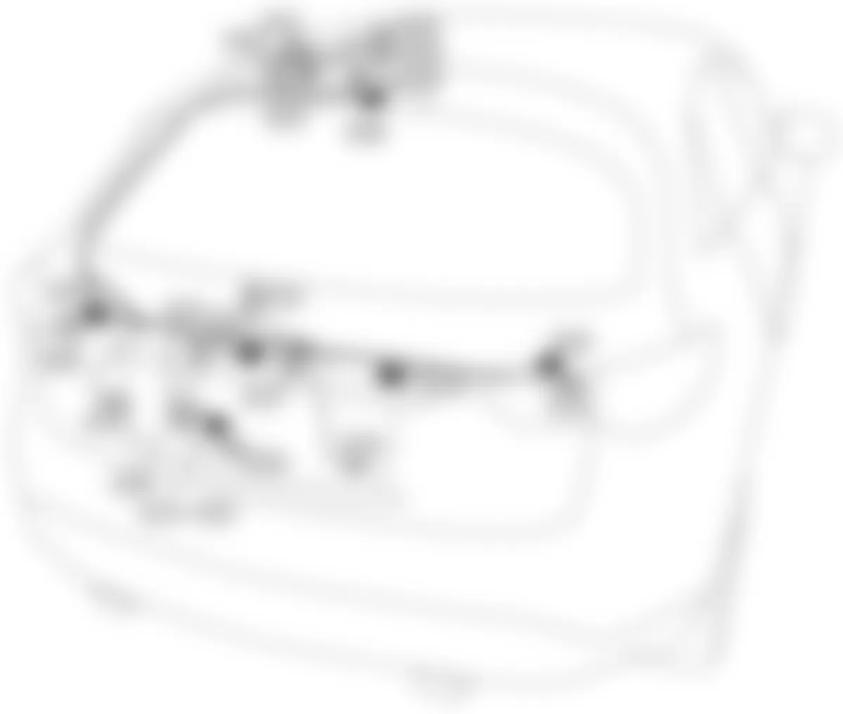
Fig. 15: Infiniti FX35 2010 - Component Locations - Fuse Block - Junction Box (J/B)
Fig. 16: Infiniti FX35 2010 - Component Locations - Fuse & Fusible Link Block
Fig. 18: Infiniti FX35 2010 - Component Locations - Engine Compartment
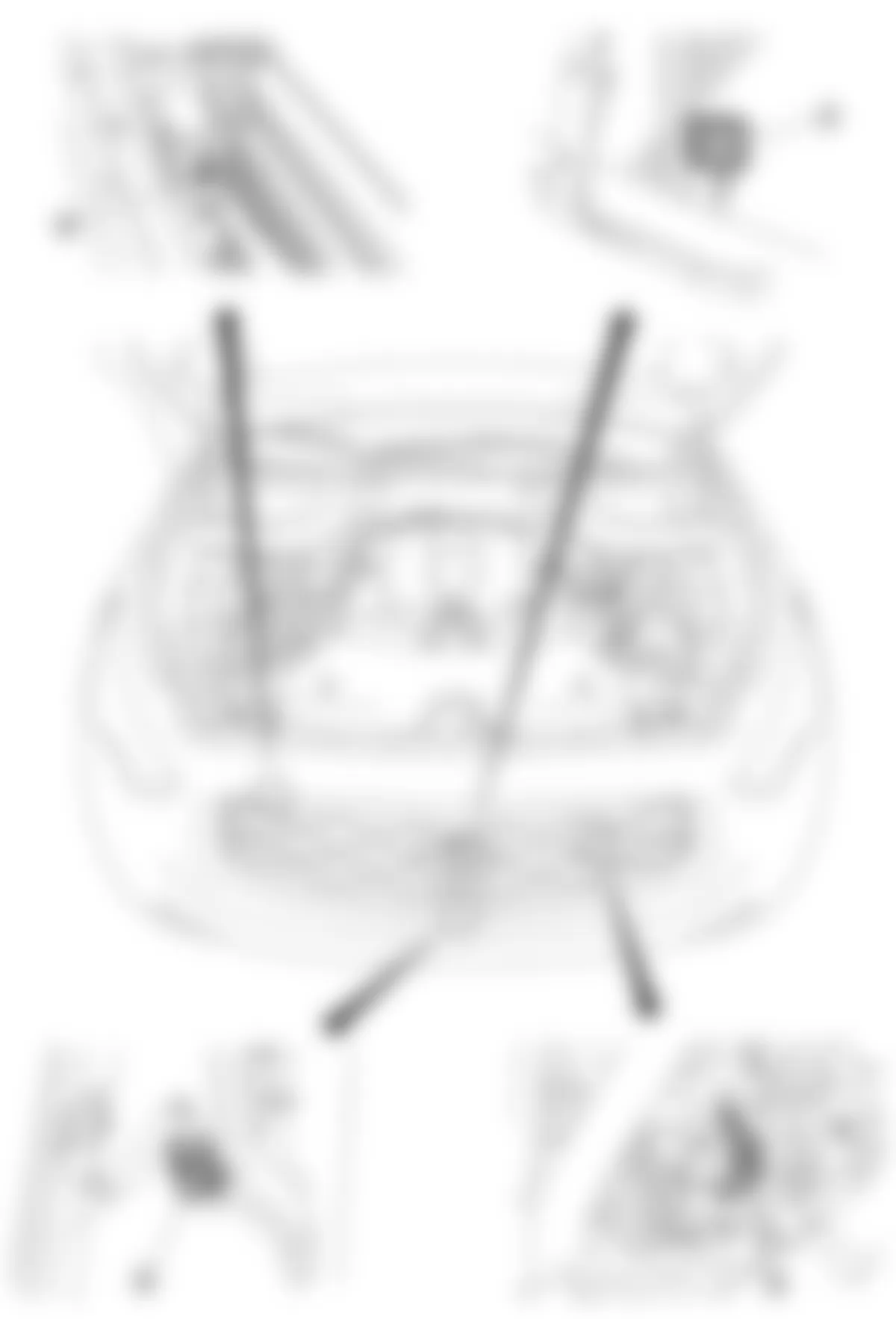
Fig. 19: Infiniti FX35 2010 - Component Locations - Dash
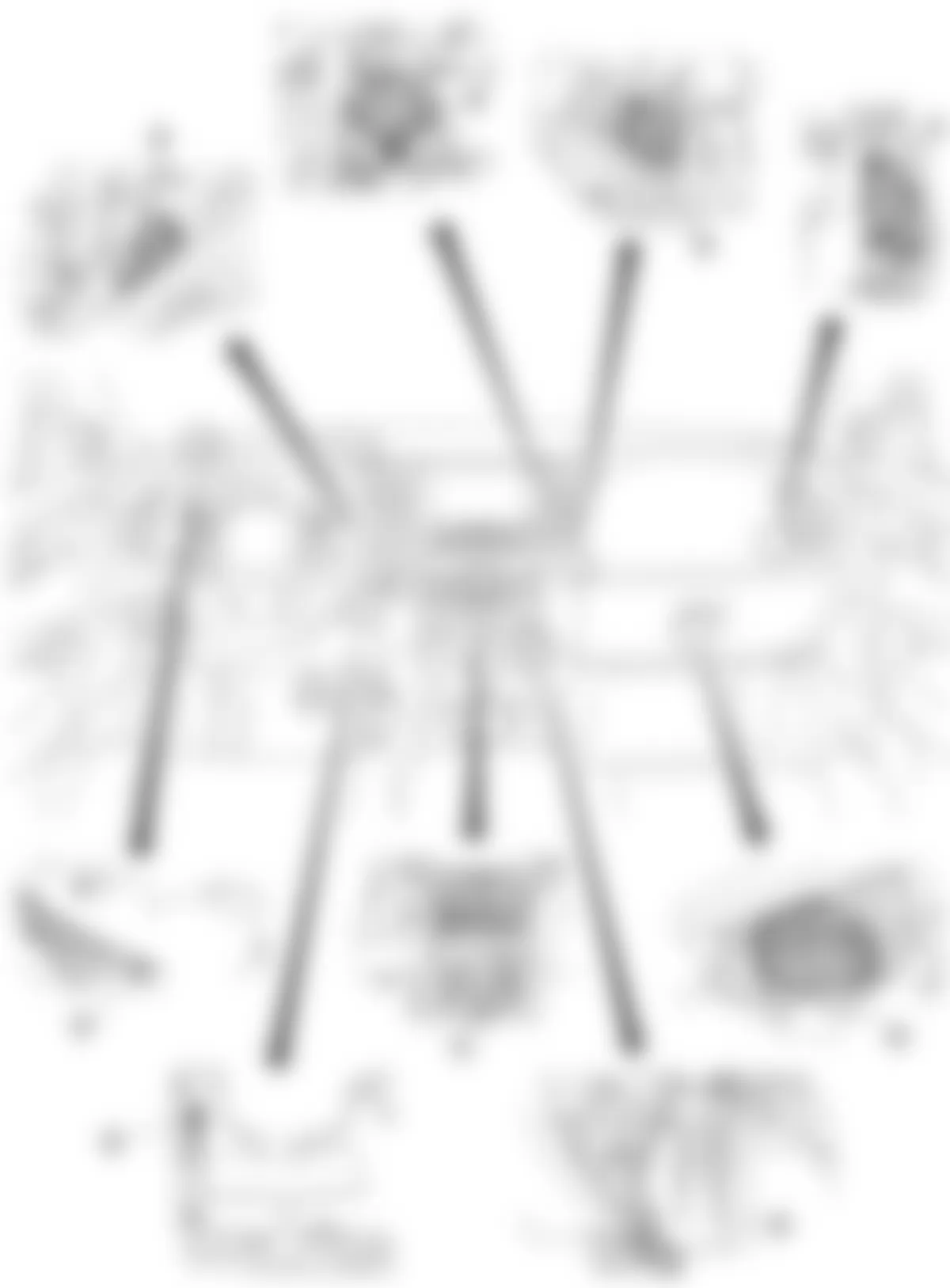
Fig. 20: Infiniti FX35 2010 - Component Locations - Seat Belt System Overview
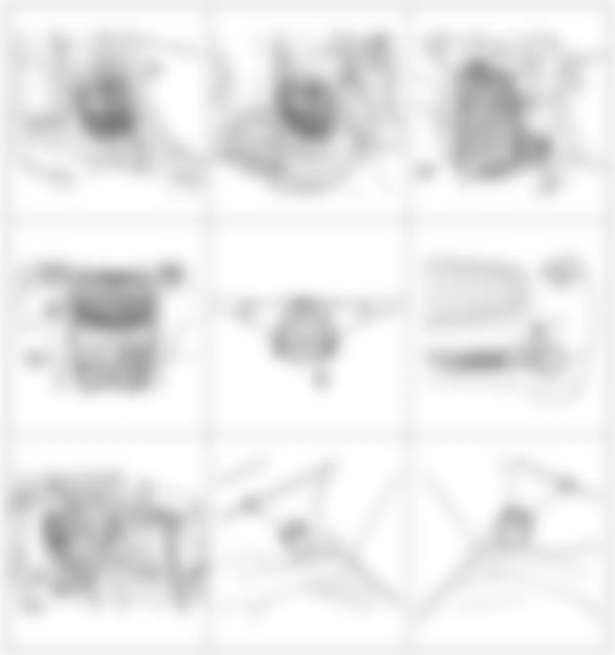
Fig. 21: Infiniti FX35 2010 - Component Locations - SRS System Overview
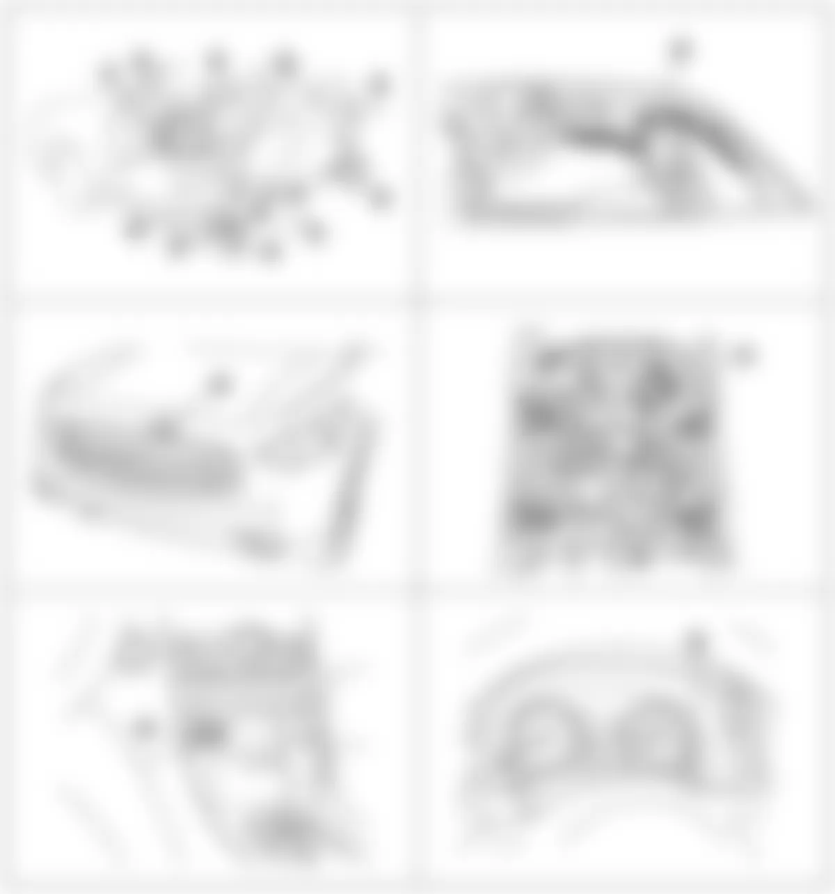
Fig. 22: Infiniti FX35 2010 - Component Locations - Engine (3.5L)
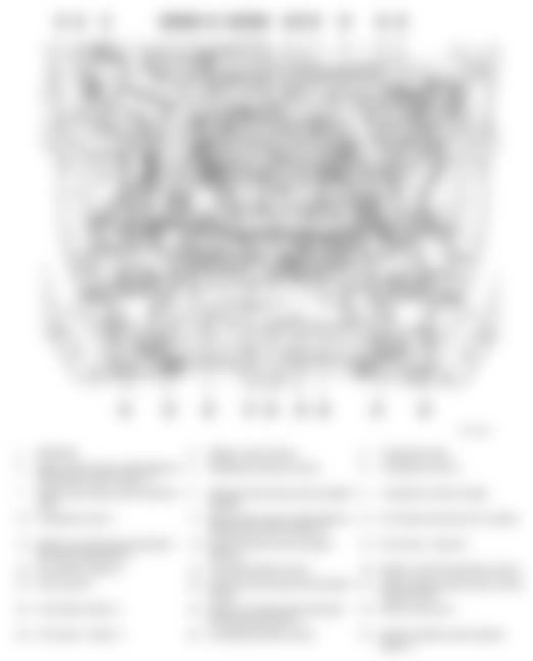
Fig. 23: Infiniti FX35 2010 - Component Locations - Engine (5.0L)