ANTI-LOCK BRAKES
Anti-lock Brake Wiring Diagrams for Jaguar XJ12 1996
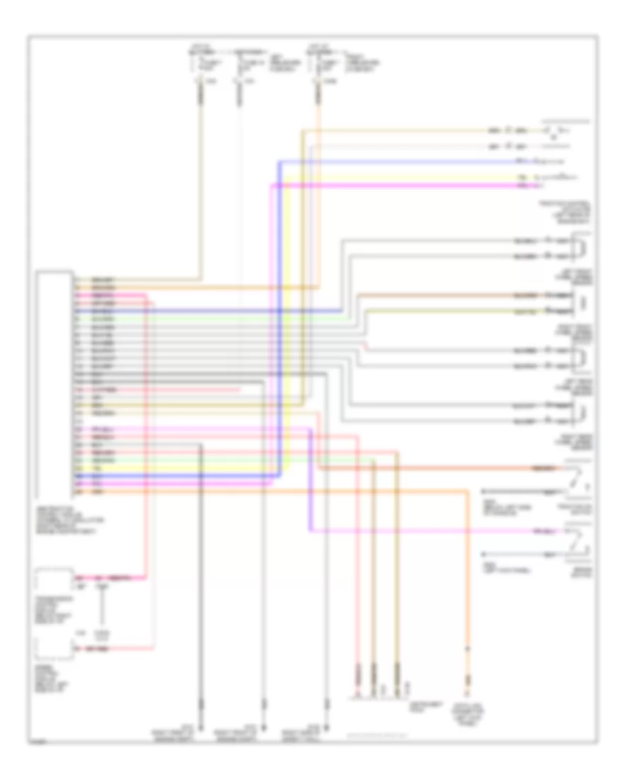
List of elements for Anti-lock Brake Wiring Diagrams for Jaguar XJ12 1996:
- Abs/traction control module (integral w/ modulator) (right rear of engine compartment)
- Brake switch
- Ca1
- Ca2
- Ca36
- Cc48
- Cc7
- Data link connector (left kick panel)
- Fc10
- Fc9
- Fuse 16 5a
- Fuse 7 30a
- G101 (right front of engine compt)
- G123 (right side of safety wall)
- G200 (left kick panel)
- G302 (below left side of console)
- Hot at all times
- Hot in run
- Instrument pack
- Left front wheel speed sensor
- Left heelboard fuse box
- Left rear wheel speed sensor
- Nca
- Right front wheel speed sensor
- Right heelboard fuse box
- Right rear wheel speed sensor
- Speed control module (below left side of i/p)
- Traction control actuator (left rear of engine bay)
- Traction on switch
- Transmission control module (below right side of i/p)
- Xj6
- Xjr & xj12
 Čeština
 Dansk
Dansk Deutsch
 Ελληνικά
 English
 English
 Español
 Suomi
Suomi Français
 Français
 עברית
עברית Hrvatski
 Magyar
 Italiano
 日本語
日本語 한국어
한국어 Nederlands
 Polski
 Português
 Português
 Română
 Slovenčina
 Slovenščina
 Svenska
 Türkçe
 中文 (中国)
 Русский