CRUISE CONTROL
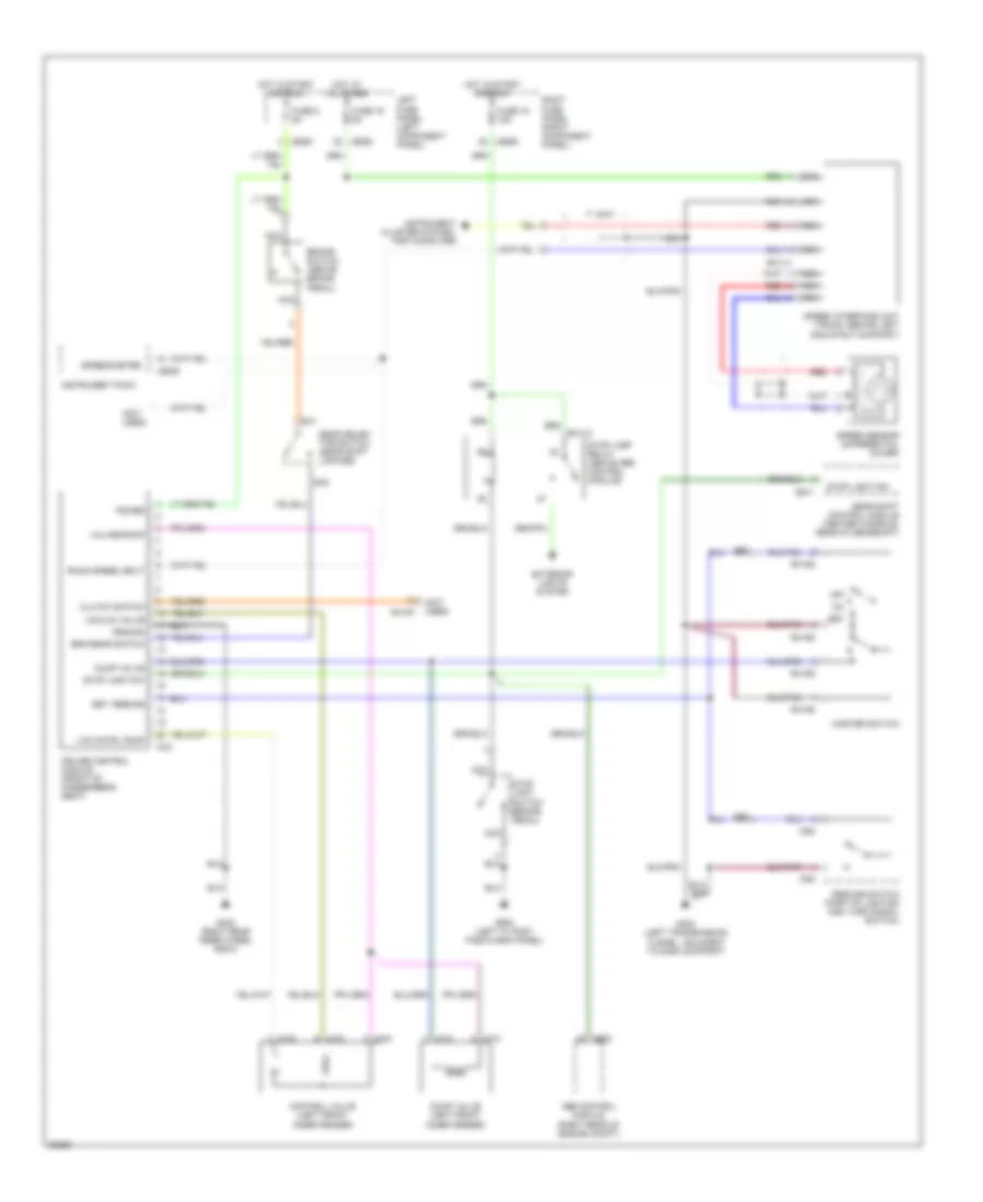
Cruise Control Wiring Diagram for Jaguar XJS 1996
List of elements for Cruise Control Wiring Diagram for Jaguar XJS 1996:
- (not used)
- Ab20
- Abs control module (right rear of engine compt)
- Brake switch (above brake pedal)
- Brk/gear switch
- Cc2
- Clutch switch
- Control valve (left front inner fender)
- Cruise control module (front of passenger's seat)
- Cs2
- Dump valve
- Dump valve (left front inner fender)
- Exterior lights system
- Fuse 16 5a
- Fuse 19 15a
- Fuse 2 5a
- G302 (left transmission tunnel, adjacent to dash support)
- G403 (right rear inner wheel arch)
- G900 (left "a" post fascia end panel)
- Gear selec- tor switch (gear shift linkage)
- Gear shift control module (center console, rear of gearshift)
- Gh1
- Gh2
- Ground
- Gs11
- Hot at all times
- Hot in start and run
- Instrument cluster system, trip computer
- Instrument pack
- Lb246
- Lb263
- Lb268
- Left fuse panel (left component panel)
- Lf13
- Lf16
- Master switch
- Nca
- Off
- Power
- Red
- Resume switch (part of lighting and turn signal switch)
- Rh113
- Rh114
- Rh197
- Rh198
- Right fuse panel (right component panel)
- Road speed input
- Set
- Set, resume
- Speed interface unit (trunk, behind left gas strut support)
- Speed sensor (differential cover)
- Speedometer
- Stop lamp relay (above abs control module)
- Stop light sw
- Stop light switch (brake pedal)
- Vac cntrl pump
- Vacuum valve
- Valves/pump
 Dansk
Dansk Deutsch
 Ελληνικά
 English
 English
 Español
 Suomi
Suomi Français
 Français
 עברית
עברית Hrvatski
 Magyar
 Italiano
 日本語
日本語 한국어
한국어 Nederlands
 Polski
 Português
 Português
 Română
 Русский
 Slovenčina
 Slovenščina
 Svenska
 Türkçe
 中文 (中国)
 Čeština