GROUND DISTRIBUTION
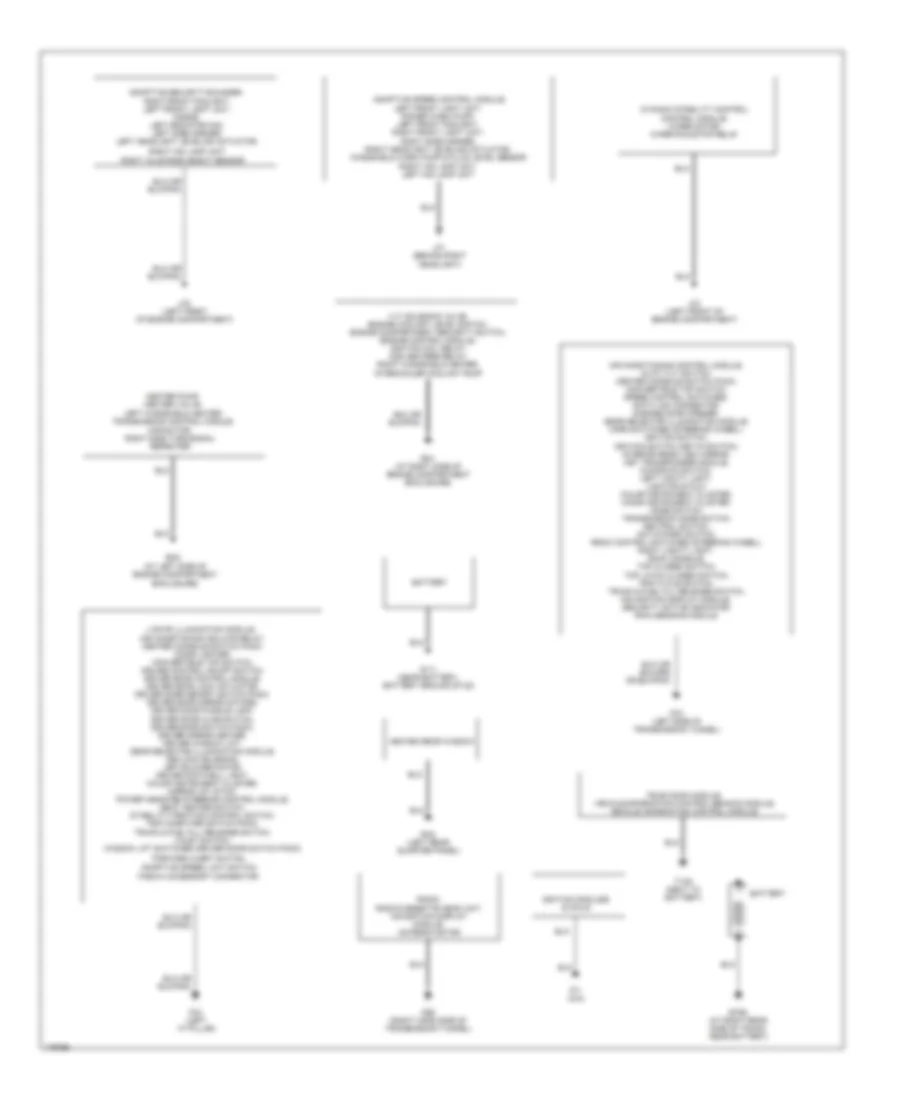
Ground Distribution Wiring Diagram (1 of 2) for Jaguar XKR 2005
List of elements for Ground Distribution Wiring Diagram (1 of 2) for Jaguar XKR 2005:
- (at left side of engine compartment enclosure)
- Adaptive security sounder, right front foglight, left front light unit, horns, left radiator fan, left side marker, left headlight leveling actuator,
- Adaptive speed control module, left front light unit, power wash pump, left front foglight, right front light unit,
- Adaptive speed limit switch,
- Air conditioning control module, auto tilt switch, center console switch pack, convertible top switch, speed control switches, data link connector, garage door opener, gear selector illumination module, horn switches (steering wheel), ignition switch, ignition switch (key-in switch), interior rear view mirror, key transponder module, kickdown switch, left vanity light, lighting stalk, major instrument cluster, minor instrument cluster, mode switch, transmission mode switch, neutral switch, not-in-park switch, radio control switches (steering wheel), right vanity light, roof console, top closed switch, top latch closed switch, trip cycle switch, trunk & fuel fill release switch, navigation display module, security active indicator, rain sensing module
- Battery
- Bt68 (at right rear side of trunk, near battery)
- Capacitor, right side turn signal repeater
- Ce2 (right hand side of transmission tunnel)
- Dynamic stability control control module, wiper motor, wiper run/stop relay
- Em1 (at right side of engine compartment enclosure)
- Em2
- Fascia accessory connector
- Fc3 (left side of transmission tunnel)
- Fc4 (left "a" pillar)
- Forward alert switch,
- G111 (near battery, battery ground stud)
- Heated rear window
- Heater pump, heater valve, left windshield heater, transmission control module,
- Ignition modules & coils
- J gate illumination module, air conditioning isolate relay, center console switch pack, cigar lighter, convertible top switch, cruise control on/off switch, driver door control module, driver door lock actuator, driver door memory switch pack, driver door mirror motors, driver door puddle lamp, driver door ajar switch, driver door switch pack, driver mirror heater, driver window lift, gear selector illumination module, keylock solenoid, left blower motor, driver footwell light, major instrument cluster, mirror joy stick, power assisted steering control module, seat heater switch, stability/traction control switch, trip computer switch pack, trunk & fuel fill release switch, valet switch, window lift switches (driver door switch pack)
- Lf1 (behind right headlight)
- Lf2 (left front of engine compartment)
- Lf3 (left front of engine compartment)
- Pi1 (n/a)
- Radio, radio/cassette head unit, navigation display module, antenna motor
- Rh2 (left rear quarter panel)
- Right axle ride height sensor
- Right hid lamp unit
- Right hid lamp unit, left hid lamp unit
- Right side marker, right headlight leveling actuator, windshield wash pump & fluid level sensor
- Television module, vehicle information control beacon module, vehicle information control module,
- Tv38 (next to battery)
- Vvt solenoid valve, engine coolant level switch, engine compartment security switch, engine control module, ignition coil relay, o2s heaters relay, right windshield heater, intercooler coolant pump
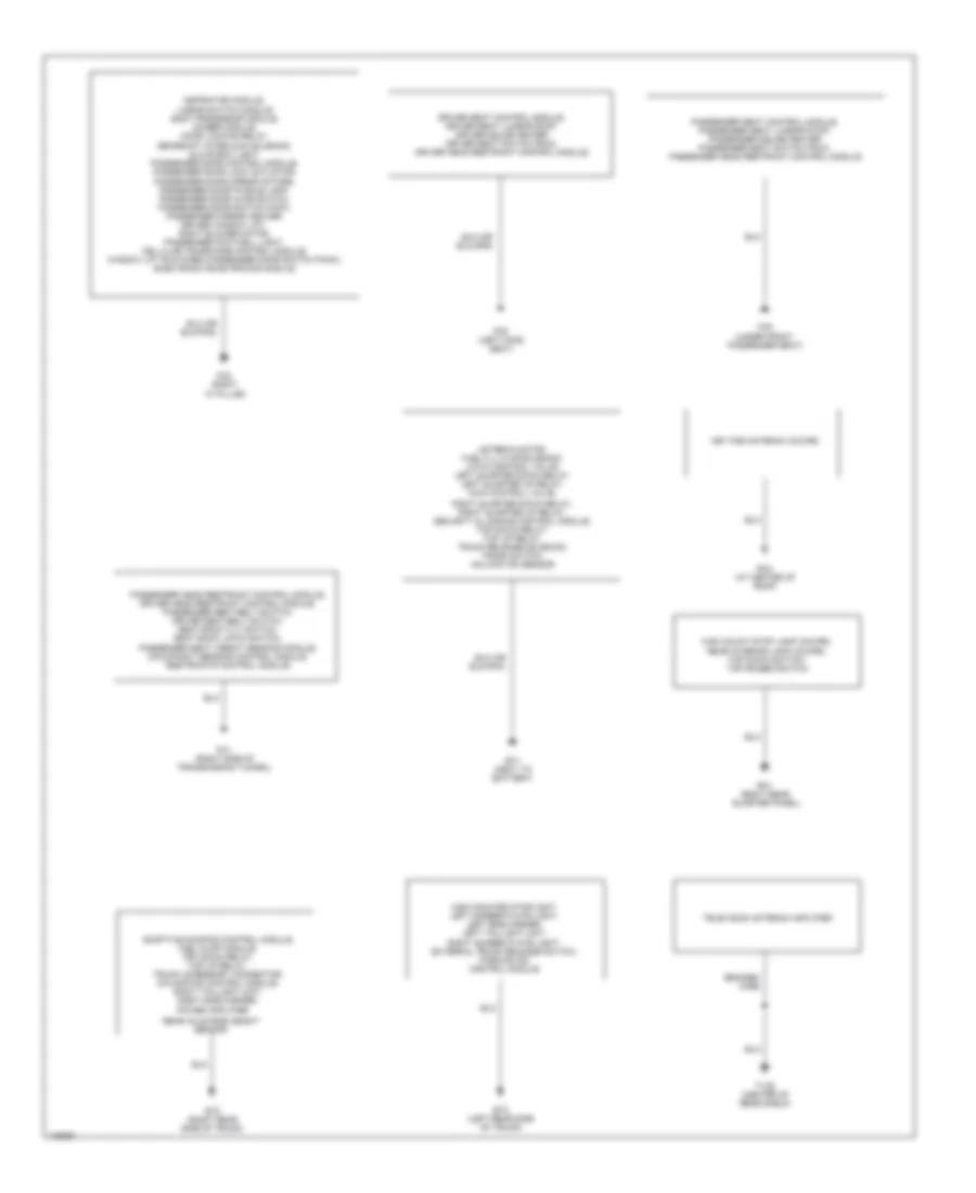
Ground Distribution Wiring Diagram (2 of 2) for Jaguar XKR 2005
List of elements for Ground Distribution Wiring Diagram (2 of 2) for Jaguar XKR 2005:
- Adaptive damping control module, fuel pump module, top down relay, top up relay, trunk accessory connector, navigation control module, right taillight unit, right side marker,
- Antenna motor, fuel fill flap solenoid, latch control valve, left quarter down relay, left quarter up relay, main control valve,
- Aspirator module, linear switch module body processor module, dimmer module, door locking relay,
- Braided wire
- Bt1 (next to battery)
- Bt2 (right rear side of trunk)
- Bt3 (left rear side of trunk)
- Driver seat control module, driver seat lumbar pump, driver squab heater driver seat switch pack, driver head restraint control module
- Fc1 (right side of transmission tunnel)
- Fc2 (right "a" pillar)
- Fc5 (under front passenger seat)
- Fc6 (left hand seat)
- Gearshift interlock solenoid, glove box light, passenger door control module, passenger door lock actuator, passenger door mirror motors, passenger door puddle lamp, passenger door ajar switch, passenger door switch pack, passenger mirror heater, driver window lift, right blower motor, passenger footwell light, cellular telephone control module, window lift switches (passenger door switch pack), electronic road pricing module
- High mount stop lamp (coupe), rear interior lamp (coupe), top down switch, top raised switch
- High mounted stoplight, left number plate light, left side marker, left taillight unit, right number plate light, external trunk release switch, parking aid control module
- Key fob antenna (coupe)
- Passenger head restraint control module, driver head restraint control module, passenger seat belt switch, driver seat belt switch, seat back tilt switch, seat back latch switch, passenger seat weight sensing module, occupancy sensing control module, restraints control module
- Passenger seat control module, passenger seat lumbar pump, passenger squab heater passenger seat switch pack, passenger head restraint control module
- Power amplifier
- Rear axle ride height sensor
- Rh1 (right rear quarter panel)
- Rh3 (at center of roof)
- Right quarter down relay, right quarter up relay, security & locking control module, top down relay, top up relay, trunk release solenoid, trunk switch, inclination sensor
- Television antenna amplifier
- Tv36 (center of rear shelf)

 Čeština
 Dansk
Dansk Deutsch
 Ελληνικά
 English
 English
 Español
 Suomi
Suomi Français
 Français
 עברית
עברית Magyar
 Italiano
 日本語
日本語 한국어
한국어 Nederlands
 Polski
 Português
 Português
 Română
 Русский
 Slovenčina
 Slovenščina
 Svenska
 Türkçe
 中文 (中国)