POWER DISTRIBUTION
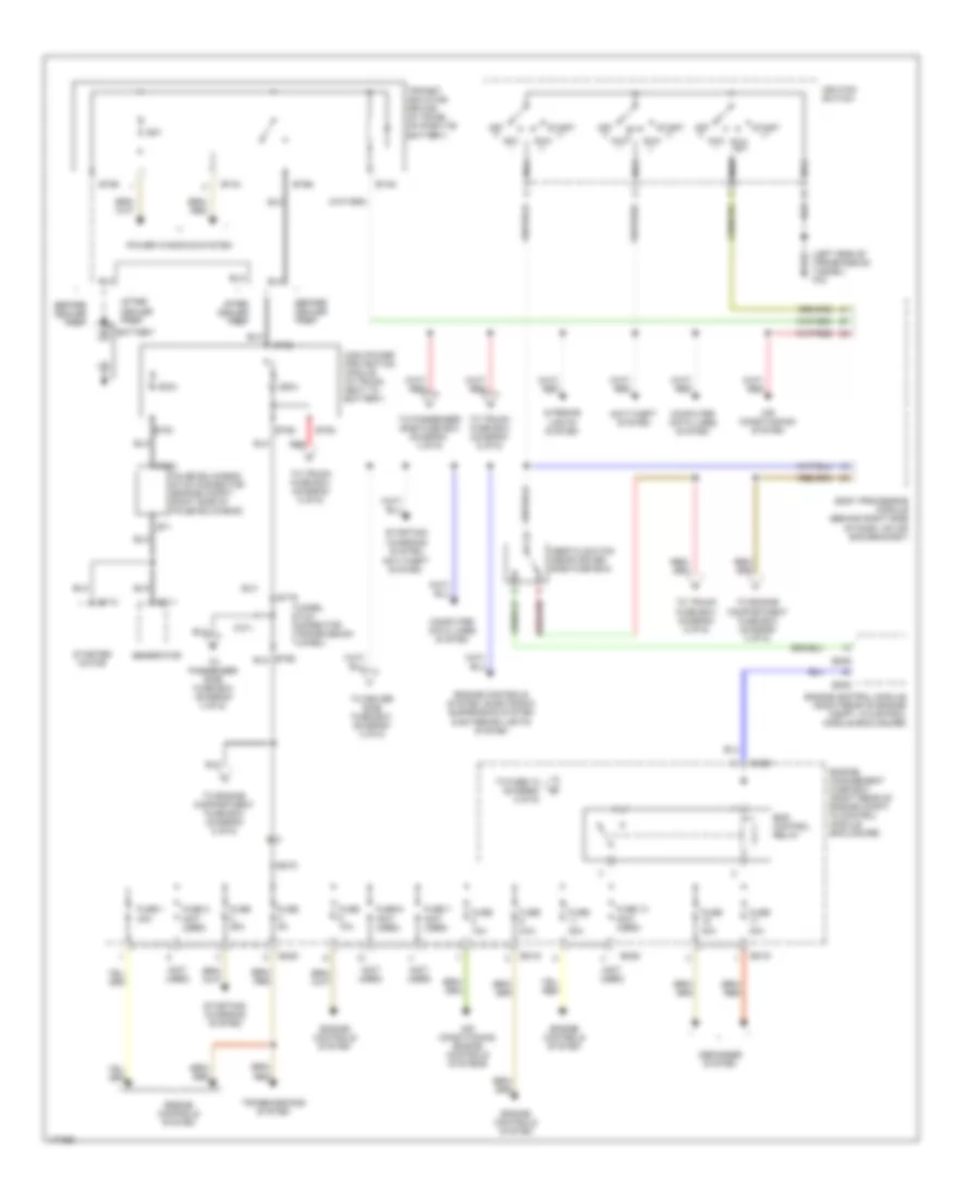
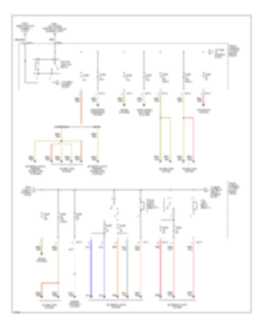
Power Distribution Wiring Diagram (1 of 6) for Jaguar XK8 2005
List of elements for Power Distribution Wiring Diagram (1 of 6) for Jaguar XK8 2005:
- (left side of transmission tunnel) fc3
- (not used)
- 250a
- 25a
- 500a
- Acc
- After dealer prep
- Air conditioning system
- Air conditioning, engine controls systems
- Anti-theft system
- Battery
- Before dealer prep
- Body processor module (behind right side of dash, on air bag bracket)
- Bt44
- Bt49
- Bt60
- Bt61
- Bt62
- Bt63
- Bt65
- Bt66
- Bt79
- Bt80
- Computer data lines system
- Defogger system
- Em19
- Em20
- Em70
- Em80
- Ems control relay
- Engine control module (right rear of engine compt, in control module enclosure)
- Engine controls system
- Engine controls system, electronic suspension system & exterior lights system
- Engine management fuse box (right rear of engine compt, in control module enclosure)
- False bulkhead stud connector (engine compt, right side of false bulkhead)
- Fc71
- Fuse 1 30a
- Fuse 10a
- Fuse 13 (not used)
- Fuse 2 (not used)
- Fuse 20a
- Fuse 25a
- Fuse 30a
- Fuse 5a
- Fuse 6 (not used)
- Fuse 7 (not used)
- Generator
- High power protection module (in trunk, next to battery)
- Ignition switch
- Iii
- Inertia switch (near dirver side fuse box)
- Interior lights system
- Nca
- Off
- Power windows system
- Red
- Run
- St1
- St10
- St11
- Start
- Starter motor
- Starting/ charging system
- Starting/ charging system,
- To driver side fuse box (diagram 3 of 6)
- To engine compartment fuse box (diagram 2 of 6)
- To fuse 10 (diagram 2 of 6)
- To passenger side fuse box (diagram 4 of 6)
- To passenger side fuse box (diagram 4 of 6)
- To trunk fuse box (diagram 6 of 6)
- To trunk fuse box (diagram 5 of 6)
- To trunk fuse box diagram 5 of 6)
- Transit isolation device (in trunk, on positive battery)
- Transmissions system
- Tunnel stud connector (transmission tunnel)
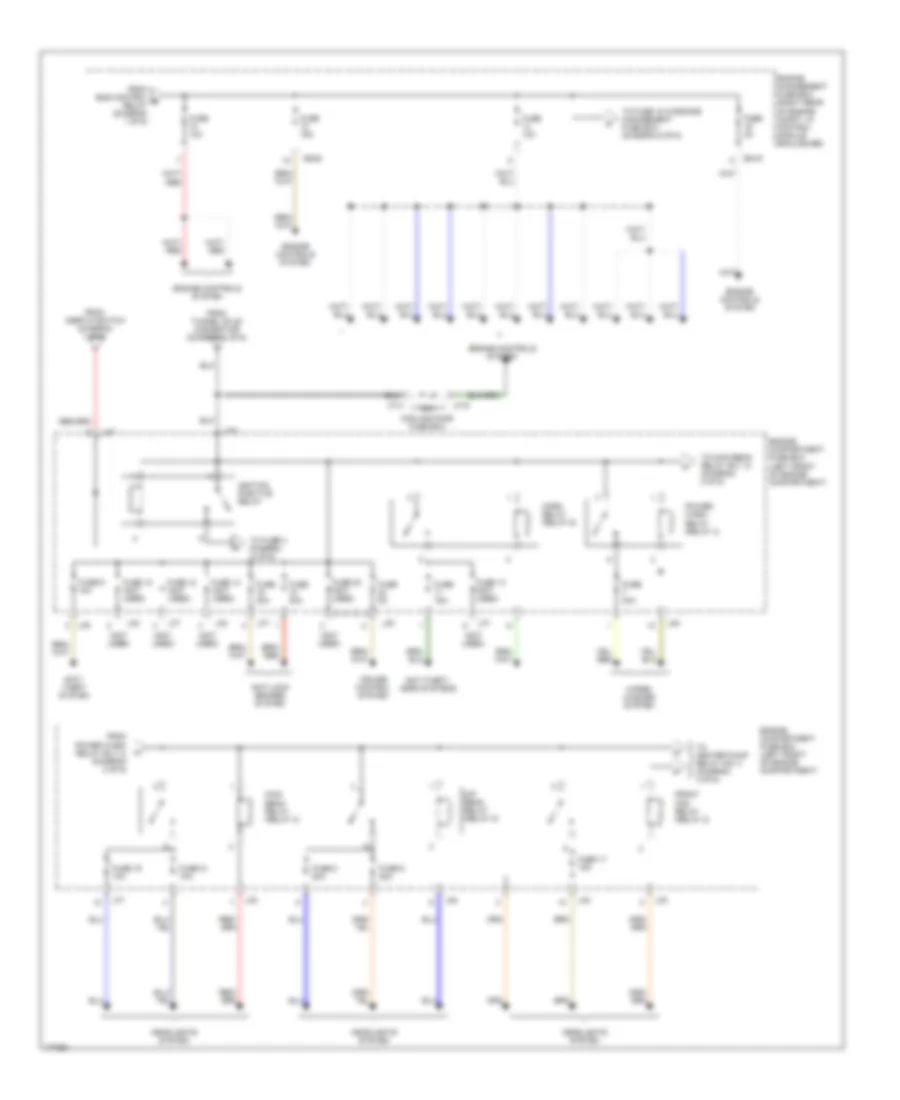
Power Distribution Wiring Diagram (2 of 6) for Jaguar XK8 2005
List of elements for Power Distribution Wiring Diagram (2 of 6) for Jaguar XK8 2005:
- (not used)
- 80a
- Anti- theft system
- Anti-lock brakes system
- Anti-theft, horn systems
- Cooling fans fuse box
- Cruise control system
- Dip beam relay (relay 5)
- Em19
- Em20
- Engine compartment fuse box (left front of engine compartment)
- Engine controls system
- Engine management fuse box (right rear of engine compt, in control module enclosure)
- From ems control e relay (diagram 1 of 6)
- From inertia switch (diagram 1 of 6)
- From power wash relay (rly 4) (diagram 2 of 6)
- From tunnel stud connector (diagram 1 of 6)
- Front fog relay (relay 2)
- Fuse 10 (not used)
- Fuse 10a
- Fuse 12 (not used)
- Fuse 13 (not used)
- Fuse 14 (not used)
- Fuse 15a
- Fuse 17 15a
- Fuse 19 10a
- Fuse 20 (not used)
- Fuse 21 10a
- Fuse 30a
- Fuse 5a
- Fuse 6 20a
- Fuse 8 20a
- Fuse 9 10a
- Headlights system
- Horn relay (relay 6)
- Ignition positive relay
- Lf14
- Lf15
- Lf5
- Lf6
- Lf7
- Lf70
- Lf8
- Main beam relay (relay 3)
- Power- wash relay (relay 4)
- To fuse 18 in engine management fuse box (diagram 6 of 6)
- To fuse 3 diagram (3 of 6)
- To heater pump relay (no 1) (diagram 3 of 6)
- To main beam relay (rly 3) (diagram 2 of 6)
- Wiper/ washer system
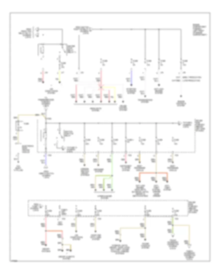
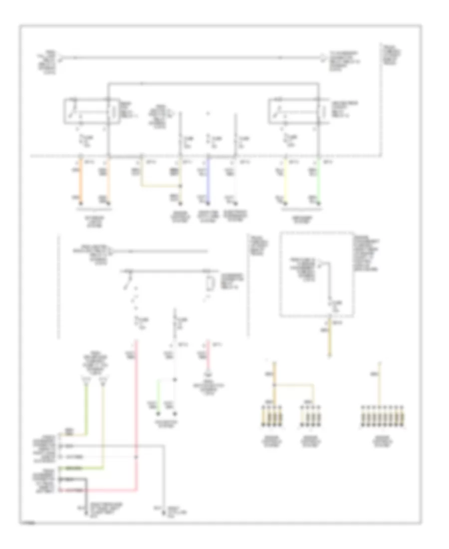
Power Distribution Wiring Diagram (3 of 6) for Jaguar XK8 2005
List of elements for Power Distribution Wiring Diagram (3 of 6) for Jaguar XK8 2005:
- (not used)
- Air conditioning system
- Anti- theft system
- Anti- theft system, garage door opener
- Anti-lock brakes system
- Anti-lock brakes, headlights, exterior lights, memory & seats systems
- Body processor module
- Computer data lines system
- Cruise control system
- Defogger system
- Driver side fuse box (behind left side of dash)
- Electronic road pricing module
- Engine compartment fuse box (left front of engine compartment)
- Engine controls system
- Fascia accessory connector (diagram 6 of 6)
- Fc2 (right "a" pillar)
- Fc5
- Fc6
- Fc92
- From front fog relay (rly 2) (diagram 2 of 6)
- From fuse 7 r (diagram 3 of 6)
- From ignition positive relay n (diagram 2 of 6)
- From inertia switch (diagram 1 of 6)
- Fuse
- Fuse 10a
- Fuse 15a
- Fuse 20a
- Fuse 25a
- Fuse 30a
- Fuse 4 5a
- Fuse 5a
- Fuse 9 (not used)
- Headlights system
- Heater pump relay (relay 1)
- Ignition positive relay
- Instrument cluster system
- Interior lights, memory, door locks, anti-theft, power windows, mirrors systems
- Lf5
- Lf6
- Lf7
- Lf8
- Memory & seats system
- Memory systems
- Mirrors, seats & memory systems
- Power windows system
- Red
- Starting/ charging system
- To fuse 10 (diagram 4 of 6)
- To fuse 8 (diagram 3 of 6)
- To passenger side fuse box (diagram 4 of 6)
- Transmissions system
- Trunk accessory connector (diagram 6 of 6)
- Wiper/washer system
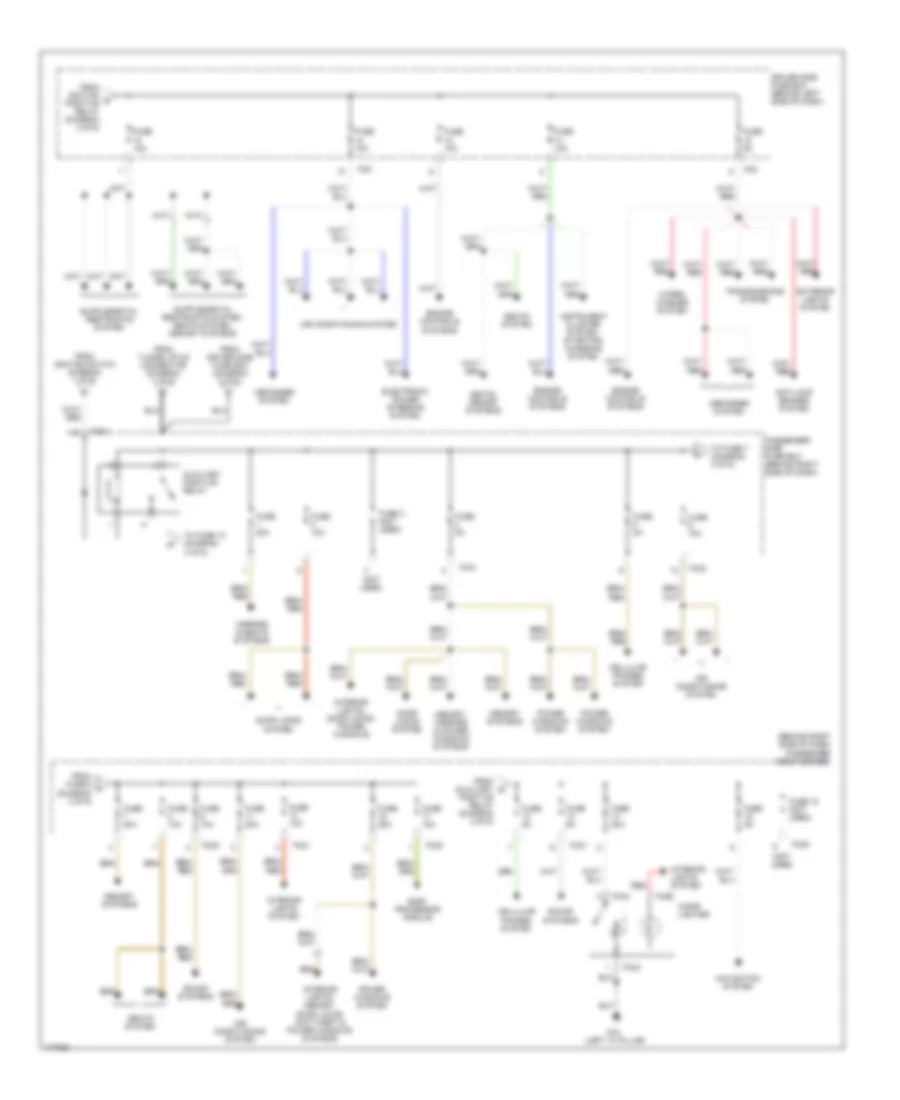
Power Distribution Wiring Diagram (4 of 6) for Jaguar XK8 2005
List of elements for Power Distribution Wiring Diagram (4 of 6) for Jaguar XK8 2005:
- (behind right side of dash) passenger side fuse box
- (left "a" pillar)
- (not used)
- Air conditioning system
- Anti-lock brakes system
- Auxiliary positive relay
- Body processor module
- Cellular phones system
- Cigar lighter
- Defogger system
- Door locks system
- Driver side fuse box (behind left side of dash)
- Electronic power steering system
- Engine controls systems
- Exterior lights system
- Fc20
- Fc21
- Fc4
- Fc42
- Fc5
- Fc59
- Fc6
- From auxiliary s
- From driver side fuse box (diagram 3 of 6)
- From fuse 6 t (diagram 4 of 6)
- From ignition q positive relay (diagram 3 of 6)
- From ignition switch (diagram 1 of 6)
- From tunnel stud connector (diagram 1 of 6)
- Fuse 10a
- Fuse 15a
- Fuse 18 (not used)
- Fuse 20a
- Fuse 25a
- Fuse 3 (not used)
- Fuse 5a
- Instrument cluster system, starting/ charging system
- Interior lights system
- Interior lights, door locks, power windows
- Interior lights, memory, door locks, anti-theft & power windows systems
- Memory systems
- Memory, mirrors & power windows systems
- Mirrors & seats systems
- Navigation system
- Passenger side fuse box (behind right side of dash)
- Positive relay (diagram 4 of 6)
- Power windows system
- Red
- Seats system
- Seats, memory systems
- Sound systems
- To fuse 10 (diagram 4 of 6)
- To fuse 7 (diagram 4 of 6)
- Transmissions system
- Wiper/ washer system
Power Distribution Wiring Diagram (5 of 6) for Jaguar XK8 2005
List of elements for Power Distribution Wiring Diagram (5 of 6) for Jaguar XK8 2005:
- Bt10
- Bt11
- Bt12
- Bt13
- Bt64
- Convertible
- Coupe
- Door locks & anti-theft systems
- Electronic suspension system
- Engine controls system
- Exterior lights system
- Exterior lights, mirrors, power tops systems
- From fuse 16 (diagram 5 of 6)
- From high power protection module (diagram 1 of 6)
- From inertia switch diagram (1 of 6)
- Fuse 10a
- Fuse 20a
- Fuse 20a (conv)
- Fuse 30a
- Fuse 40a (conv)
- Fuse 5a
- Ignition positive relay
- Navigation system
- Power tops system
- Red
- Sound systems
- Stop lamp relay (relay 5)
- Tail lamp relay (relay 3)
- To fuse (diagram 5 of 6)
- To fuse 3 diagram (6 of 6)
- To rear fog relay (relay 1) (diagram 6 of 6)
- Trunk fuse box (at right side of trunk)
Power Distribution Wiring Diagram (6 of 6) for Jaguar XK8 2005
List of elements for Power Distribution Wiring Diagram (6 of 6) for Jaguar XK8 2005:
- (relay 5) (diagram 5 of 6)
- (right "a" pillar) fc2
- (right rear side of trunk, next to battery) bt2
- Accessory connector relay (relay 6)
- Bt10
- Bt11
- Bt12
- Bt13
- Computer data lines system
- Defogger system
- Electronic suspension system
- Em19
- Engine controls system
- Engine management fuse box (right rear of engine compt, in control module enclosure)
- Exterior lights system
- Fascia accessory connector (near to right hand side of glove box)
- From driver side fuse box (fuse 17, 10a) (diagram 3 of 6)
- From fuse 16 in engine z management fuse box (diagram 2 of 6)
- From heated backlight relay x (relay 2) (diagram 6 of 6)
- From ignition positive u
- From ignition switch (diagram 1 of 6)
- From tail lamp relay w
- Fuse 10a
- Fuse 25a
- Fuse 30a
- Fuse 5a
- Heated rear window relay (relay 2)
- Navigation system
- Rear fog relay (relay 1)
- Relay (diagram 5 of 6)
- To accessory connector relay (relay 6) (diagram 6 of 6)
- Trunk accessory connector (in trunk, near to battery)
- Trunk fuse box (at right side of trunk)

 Čeština
 Dansk
Dansk Deutsch
 Ελληνικά
 English
 English
 Español
 Suomi
Suomi Français
 Français
 עברית
עברית Hrvatski
 Magyar
 日本語
日本語 한국어
한국어 Nederlands
 Polski
 Português
 Português
 Română
 Русский
 Slovenčina
 Slovenščina
 Svenska
 Türkçe
 中文 (中国)