STARTING/CHARGING
4.0L
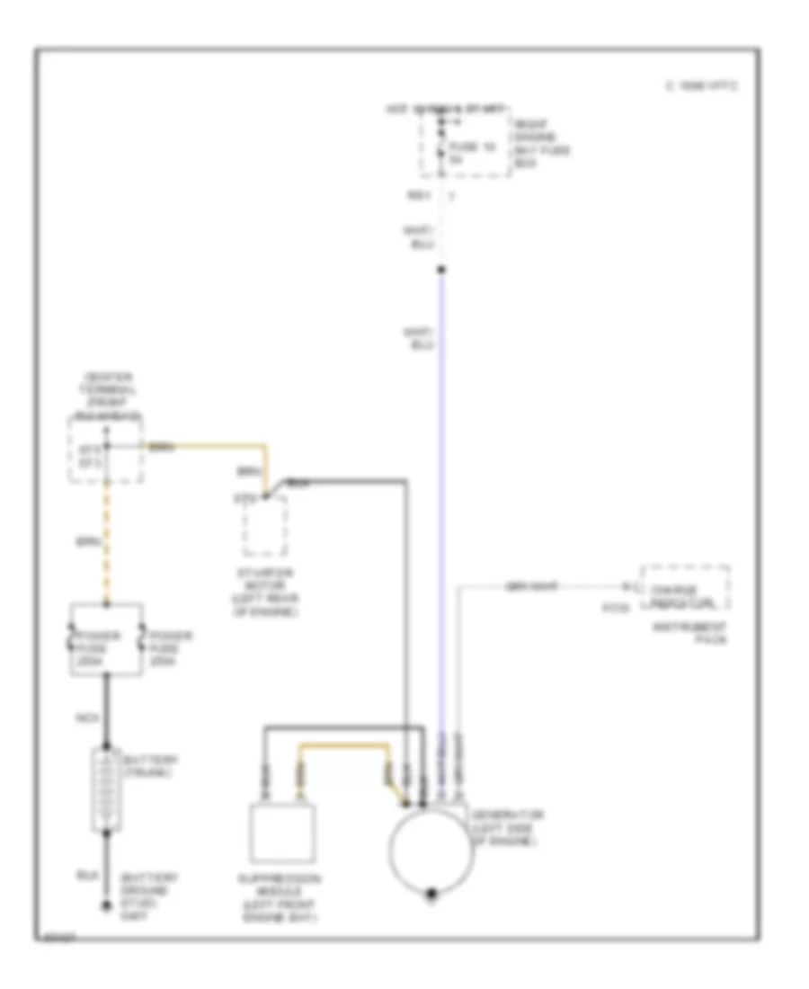
4.0L, Charging Wiring Diagram for Jaguar XJ6 Vanden Plas 1995
List of elements for 4.0L, Charging Wiring Diagram for Jaguar XJ6 Vanden Plas 1995:
- (battery ground stud) g401
- 1996 vftc c
- Battery (trunk)
- Center terminal (front bulkhead)
- Charge indicator
- Fc10
- Fuse 10 5a
- Generator (left side of engine)
- Hot in run & start
- Instrument pack
- Nca
- Power fuse 250a
- Right engine bay fuse box
- Rs1
- St2
- St5 st3
- Starter motor (left rear of engine)
- Suppression module (left front engine bay)
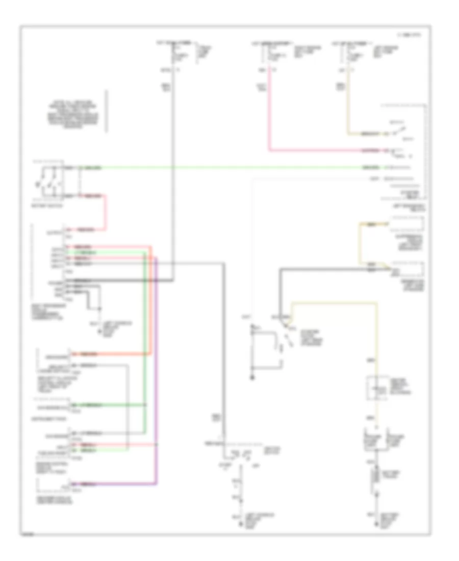
4.0L, Starting Wiring Diagram for Jaguar XJ6 Vanden Plas 1995
List of elements for 4.0L, Starting Wiring Diagram for Jaguar XJ6 Vanden Plas 1995:
- (battery ground stud) g401
- (left console ground stud) g206
- 1996 vftc c
- Acc
- An1/ st4
- Arm/disarm
- Battery (trunk)
- Body processor module (passenger's underscuttle)
- Bt35
- Ca21
- Cc13
- Center terminal (front bulkhead)
- Chk engine
- Chk engine (mil)
- Data
- Decoder module (center console)
- Engine control module (right "a" post)
- Fc1
- Fc10
- Fc2
- Fc3
- Fueling inhibit
- Fuse 12 10a
- Fuse 3 25a
- Fuse 5 10a
- Generator (left side of engine)
- Gnd
- Hot at all times
- Hot in run & start
- Ignition switch
- Iii
- Input
- Instrument pack
- Left engine bay fuse box
- Left engine bay relays
- Ls1
- Nca
- Note: all vehicles require "check engine" signal input to body processor module before body processor module enables engine cranking
- Off
- Output
- P,n
- Pi104
- Pi105
- Power
- Power fuse 250a
- Right engine bay fuse box
- Rotary switch
- Rs1
- Run
- Security & locking control module (left front of trunk)
- Security immobilization
- St1
- St2
- St5 st3
- Start
- Starter motor (left rear of engine)
- Starter relay
- Suppression module (left front engine bay)
- Trunk fuse box

 Čeština
 Dansk
Dansk Deutsch
 Ελληνικά
 English
 Español
 Suomi
Suomi Français
 Français
 עברית
עברית Hrvatski
 Magyar
 Italiano
 日本語
日本語 한국어
한국어 Nederlands
 Polski
 Português
 Português
 Română
 Русский
 Slovenčina
 Slovenščina
 Svenska
 Türkçe
 中文 (中国)