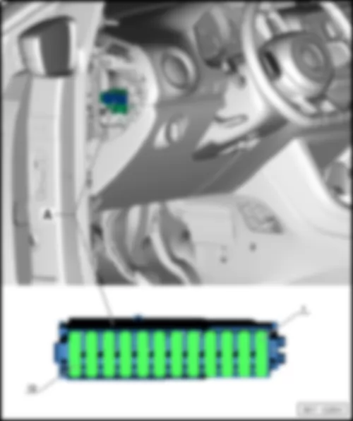
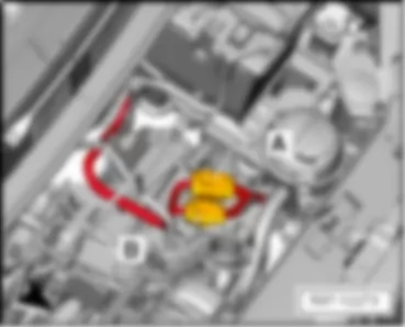
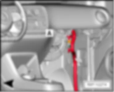
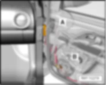
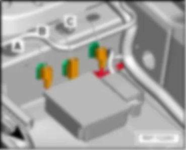
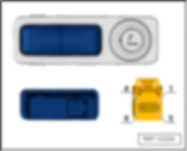
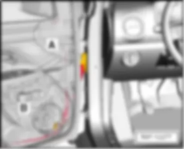
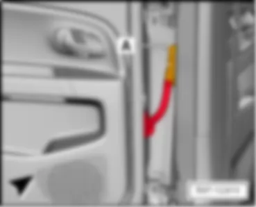
Wiring Diagram VW UP 2012 - Rotary light switch - Heater control unit - Fresh air blower series resistor with overheating fuse - Fresh air blower

E1 | Light switch |
EX1 | Rotary light switch |
E9 | Fresh air blower switch |
J162 | Heater control unit |
J519 | Onboard supply control unit |
N24 | Fresh air blower series resistor with overheating fuse |
SC4 | Fuse 4 on fuse holder C |
SC37 | Fuse 37 on fuse holder C |
T2bh | 2-pin connector |
T2bk | 2-pin connector |
T4s | 4-pin connector |
T5b | 5-pin connector |
T16g | 16-pin connector |
T17 | 17-pin connector |
T73b | 73-pin connector |
V2 | Fresh air blower |
43 | Earth point, lower part of right A-pillar |
44 | Earth point, lower part of left A-pillar |
383 | Earth connection 18, in main wiring harness |
386 | Earth connection 21, in main wiring harness |
A19 | Connection (58d), in dash panel wiring harness |
L77 | Connection, in fresh air blower wiring harness |
* | Only models with start/stop system |
*2 | From May 2012 |
*3 | Only models with no start/stop system |
VW UP 2012
VW UP 2012 Overview of control units
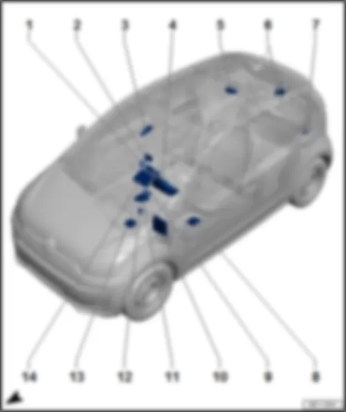
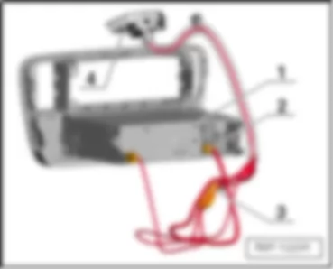
Overview of control units1 - | Heater control unit -J162- |
q | Fitting location → Chapter |
1 - | Air conditioning system control unit -J301- |
q | Fitting location → Chapter |
2 - | PID (portable navigation and infotainment system) -J982- |
q | Fitting location → Chapter |
3 - | Emergency braking function sensor unit -J939- |
q | Fitting location → Chapter |
4 - | Control unit in dash panel insert -J285- |
q | Fitting location → Chapter |
5 - | Sliding sunroof control unit -J245- |
q | Fitting location → Chapter |
6 - | Rear window wiper motor -V12- |
q | Fitting location → Chapter |
7 - | Parking aid control unit -J446- |
q | Fitting location → Chapter |
8 - | DC/DC voltage converter -A19- |
q | Fitting location → Chapter |
9 - | Amplifier -R12- |
q | Fitting location → Chapter |
10 - | Onboard supply control unit -J519- |
q | Fitting location left-hand drive → Chapter |
q | Fitting location, right-hand drive → Anchor |
11 - | Power steering control unit -J500- |
q | Fitting location left-hand drive → Chapter |
q | Fitting location, right-hand drive → Anchor |
12 - | Heated front seats control unit -J774- |
q | Fitting location left-hand drive → Chapter |
q | Fitting location, right-hand drive → Anchor |
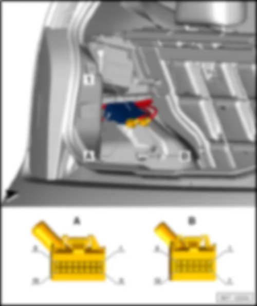
13 - | Airbag control unit -J234- |
q | Fitting location → Chapter |
14 - | Radio -R- |
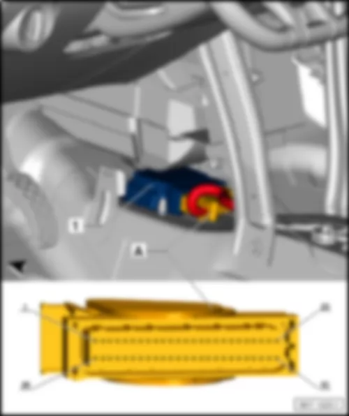
VW UP 2012 Airbag control unit -J234-
|
1 - | Airbag control unit -J234- |
q | -A- 50-pin connector, -T50- |
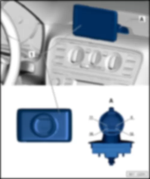
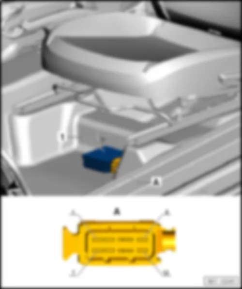
VW UP 2012 PID (portable navigation and infotainment system) -J982-
|
1 - | PID (portable navigation and infotainment system) -J982- |
q | -A- 16-pin connector -T16e- |
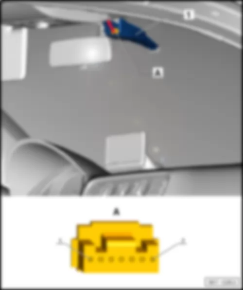
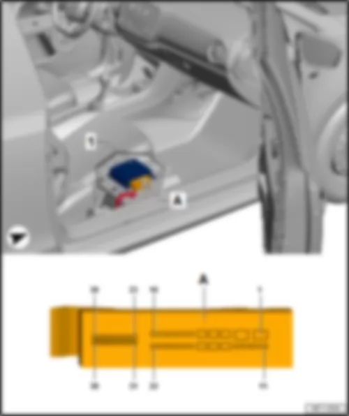
VW UP 2012 Emergency braking function sensor unit -J939-
|
1 - | Emergency braking function sensor unit -J939- |
q | -A- 7-pin connector -T7c- |
|
-T7c- | Designation |
1 | -- |
2 | -- |
3 | Powertrain CAN low |
4 | Powertrain CAN, high |
5 | Terminal 15 |
6 | -- |
7 | Terminal 31 |
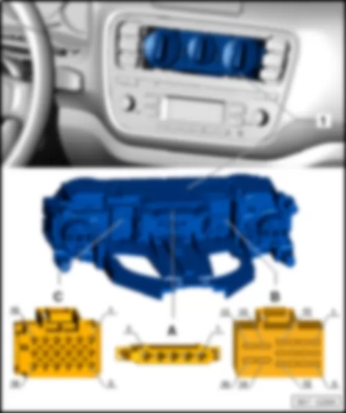
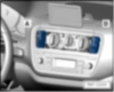
VW UP 2012 Heater control unit -J162-
|
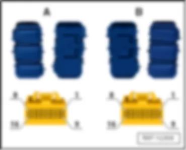
1 - | Heater control unit -J162- |
q | -A- 5-connector -T5b- |
q | -B- 16-pin connector -T16g- |
q | -C- 18-pin connector -T18- |
|
-T5b- | Designation | -T16g- | Designation | -T18- | Designation | ||
1 | 4th blower speed | 1 | -- | 1 | -- | ||
2 | 3rd blower speed | 2 | -- | 2 | -- | ||
3 | 2nd blower speed | 3 | -- | 3 | -- | ||
4 | 1st blower speed | 4 | -- | 4 | -- | ||
5 | Supply +12V | 5 | -- | 5 | -- | ||
6 | -- | 6 | -- | ||||
7 | -- | 7 | -- | ||||
8 | -- | 8 | -- | ||||
9 | -- | 9 | -- | ||||
10 | Terminal 31 | 10 | -- | ||||
11 | -- | 11 | -- | ||||
12 | Terminal 58d | 12 | -- | ||||
13 | -- | 13 | -- | ||||
14 | -- | 14 | -- | ||||
15 | -- | 15 | -- | ||||
16 | -- | 16 | -- | ||||
17 | -- | ||||||
18 | -- |
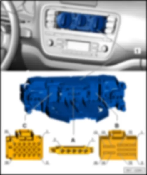
VW UP 2012 Air conditioning system control unit -J301-
|
1 - | Air conditioning system control unit -J301- |
q | -A- 5-connector -T5b- |
q | -B- 16-pin connector -T16g- |
q | -C- 18-pin connector -T18- |
|
-T5b- | Designation | -T16g- | Designation | -T18- | Designation | ||
1 | 4th blower speed | 1 | AC signal | 1 | -- | ||
2 | 3rd blower speed | 2 | Evaporator earth | 2 | -- | ||
3 | 2nd blower speed | 3 | Evaporator signal | 3 | Evaporator temperature sensor signal | ||
4 | 1st blower speed | 4 | -- | 4 | Evaporator temperature sensor earth | ||
5 | Supply +12V | 5 | -- | 5 | -- | ||
6 | -- | 6 | -- | ||||
7 | -- | 7 | -- | ||||
8 | -- | 8 | -- | ||||
9 | -- | 9 | -- | ||||
10 | Terminal 31 | 10 | -- | ||||
11 | Terminal 15 | 11 | -- | ||||
12 | Terminal 58d | 12 | -- | ||||
13 | -- | 13 | -- | ||||
14 | -- | 14 | -- | ||||
15 | -- | 15 | -- | ||||
16 | -- | 16 | -- | ||||
17 | -- | ||||||
18 | -- |
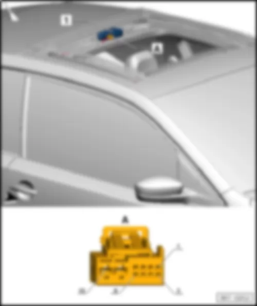
VW UP 2012 Sliding sunroof control unit -J245-
|
1 - | Sliding sunroof control unit -J245- |
q | -A- 10-pin connector -T10a- |
|
-T10a- | Designation |
1 | LIN |
2 | Sliding sunroof adjustment regulator supply |
3 | Sliding sunroof adjustment regulator slider |
4 | Sliding sunroof adjustment regulator earth |
5 | -- |
6 | -- |
7 | Sunroof button, pull/push |
8 | -- |
9 | Terminal 31 |
10 | Terminal 30 |
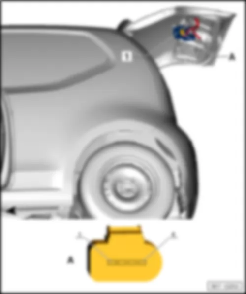
VW UP 2012 Rear window wiper motor -V12-
|
1 - | Rear window wiper motor -V12- |
q | -A- 4-pin connector -T4a- |
|
-T4a- | Designation |
1 | Terminal 31 |
2 | Steering column switch, intermittent |
3 | Steering column switch, rear wash |
4 | Terminal 75 |
VW UP 2012 Parking aid control unit -J446-
|
1 - | Parking aid control unit -J446- |
q | A = 16-pin connector -T16- |
q | B - 12-pin connector -T12c- |
|
-T16- | Designation | -T12c- | Designation | |
1 | Terminal 15 | 1 | -- | |
2 | Rear sound sender signal | 2 | -- | |
3 | -- | 3 | Rear, centre sensor signal | |
4 | -- | 4 | Rear, right sensor signal | |
5 | -- | 5 | Rear, left sensor signal | |
6 | Powertrain CAN, high | 6 | -- | |
7 | -- | 7 | -- | |
8 | Terminal 31 | 8 | Rear sensor earth | |
9 | -- | 9 | -- | |
10 | Rear sound sender supply | 10 | -- | |
11 | -- | 11 | Rear sensor current | |
12 | -- | 12 | -- | |
13 | -- | |||
14 | -- | |||
15 | Powertrain CAN low | |||
16 | -- |
VW UP 2012 Heated front seats control unit -J774-
Note
|
1 - | Heated front seats control unit -J774- |
q | -A- 16-pin connector -T16a- |
Note
|
1 - | Heated front seats control unit -J774- |
q | -A- 16-pin connector -T16a- |
|
-T16a- | Designation | Designation | ||
1 | LED, stage 1, right | 9 | Terminal 31 | |
2 | LED, stage 2, left | 10 | -- | |
3 | LED, stage 2, right | 11 | -- | |
4 | LED, stage 1, left | 12 | Button for right seat heating | |
5 | Seat heating authorisation, BCM | 13 | Terminal 75 | |
6 | Button for left seat heating | 14 | Terminal 75 | |
7 | -- | 15 | Seat heating left | |
8 | -- | 16 | Seat heater right |
VW UP 2012
|
1 - | DC/DC voltage converter -A19- |
q | -A- 12-pin connector -T12a- |
|
-T12a- | Designation |
1 | Terminal 30 |
2 | Terminal 31 |
3 | Terminal 15 |
4 | Terminal 50 |
5 | -- |
6 | -- |
7 | Terminal 30 stab |
8 | -- |
9 | -- |
10 | -- |
11 | -- |
12 | -- |
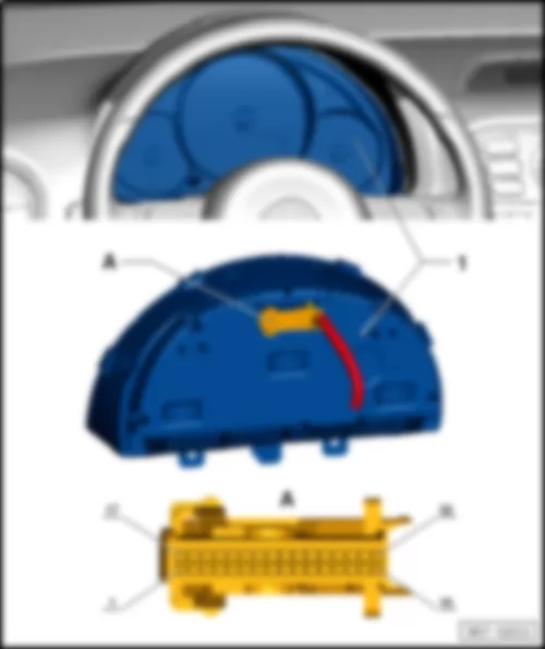
VW UP 2012 Control unit in dash panel insert -J285-
|
1 - | Control unit in dash panel insert -J285- |
q | A- 32-pin connector -T32- |
|
-T32- | Designation | Designation | ||
1 | Tank sender 1 full | 17 | -- | |
2 | Tank sender 1 empty | 18 | Low coolant level | |
3 | -- | 19 | Ambient temperature | |
4 | -- | 20 | Terminal 31 sensor earth | |
5 | -- | 21 | MFD to | |
6 | -- | 22 | MFD from | |
7 | Transponder 1 | 23 | MFD OK/Reset | |
8 | Transponder 2 | 24 | Belt latch | |
9 | Speedometer output | 25 | Parking brake/EPB | |
10 | Speedometer input | 26 | Brakes, general | |
11 | -- | 27 | Oil pressure | |
12 | -- | 28 | Powertrain CAN, high | |
13 | Rear fog light | 29 | Powertrain CAN low | |
14 | Main beam | 30 | -- | |
15 | -- | 31 | Terminal 15 | |
16 | Terminal 31 | 32 | Terminal 30 |
VW UP 2012 Power steering control unit -J500-
Note
|
1 - | Power steering control unit -J500- |
q | -A- 2-pin connector -T2aq- |
q | -B- 3-pin connector -T3p- |
q | -C- 6-pin connector -T6i- |
q | -D- 6-pin connector -T6j- |
Note
|
1 - | Power steering control unit -J500- |
q | -A- 2-pin connector -T2aq- |
q | -B- 3-pin connector -T3p- |
q | -C- 6-pin connector -T6i- |
q | -D- 6-pin connector -T6j- |
|
-T2aq- | Designation | -T3p- | Designation | |
1 | Terminal 31 | 1 | Powertrain CAN low | |
2 | Terminal 30A | 2 | Powertrain CAN, high | |
3 | Terminal 15 |
VW UP 2012 Amplifier R12
|
1 - | Amplifier -R12- |
q | -A- 38-pin connector -T38a- |
|
-T38a- | Designation | Designation | ||
1 | Terminal 31 | 20 | Front left treble loudspeaker -R20- , - | |
2 | Terminal 30 | 21 | Rear left loudspeaker -R4- , - | |
3 | Front right loudspeaker -R3- , - | 22 | Rear right loudspeaker -R5- , + | |
4 | -- | 23 | Convenience CAN bus high | |
5 | -- | 24 | -- | |
6 | Front left loudspeaker -R2- , - | 25 | -- | |
7 | Front right treble loudspeaker -R22- , - | 26 | -- | |
8 | Front left treble loudspeaker -R20- , + | 27 | LR IN, - | |
9 | Rear left loudspeaker -R4- , + | 28 | RR IN, - | |
10 | Rear right loudspeaker -R5- , - | 29 | LF IN, - | |
11 | Subwoofer -R211- , - | 30 | RF IN,- | |
12 | Subwoofer -R211- , + | 31 | Convenience CAN bus low | |
13 | Subwoofer -R211- , + | 32 | -- | |
14 | Subwoofer -R211- , - | 33 | -- | |
15 | Front right loudspeaker -R3- , + | 34 | -- | |
16 | -- | 35 | LR IN. + | |
17 | -- | 36 | RR IN, + | |
18 | Front left loudspeaker -R2- , + | 37 | LF IN, + | |
19 | Front right treble loudspeaker -R22- , + | 38 | RF IN, + |
VW UP 2012 Onboard supply control unit -J519-
Note
|
1 - | Onboard supply control unit -J519- |
q | -A- 73-pin connector -T73a-, black |
q | -B- 73-pin connector -T73b-, white |
Note
|
1 - | Onboard supply control unit -J519- |
q | -A- 73-pin connector -T73a-, black |
q | -B- 73-pin connector -T73b-, white |
|
-T73a- | Designation | -T73b- | Designation | |
1 | -- | 1 | -- | |
2 | Left dipped beam | 2 | Right dipped beam | |
3 | -- | 3 | Left daytime running lights | |
4 | Interior light dimmer | 4 | 58D supply | |
5 | Right daytime running lights | 5 | -- | |
6 | Rear fog light | 6 | -- | |
7 | Fog light, lighting rotary switch | 7 | Number plate light | |
8 | -- | 8 | -- | |
9 | Emergency braking function button | 9 | Left fog light with cornering light | |
10 | Central locking authorisation motor, rear lid | 10 | Right fog light with cornering light | |
11 | Central locking, lock motor, driver | 11 | Terminal 30 reversing lights, dipped beam | |
12 | Central locking, common motor, driver | 12 | Reversing light | |
13 | Central locking, safe, driver | 13 | Terminal 30 left turn signal/brake light | |
14 | Terminal 31 central locking | 14 | Left turn signal | |
15 | Central locking motor front passenger | 15 | Right turn signal | |
16 | Terminal 30 central locking | 16 | Brake light | |
17 | -- | 17 | -- | |
18 | -- | 18 | Powertrain CAN low | |
19 | Driver door rotary latch | 19 | Powertrain CAN high | |
20 | Passenger door rotary latch | 20 | Convenience CAN high | |
21 | Central locking status lock, front passenger | 21 | Convenience CAN low | |
22 | Central locking status lock, driver | 22 | CAN diagnosis low | |
23 | Unlock rear lid | 23 | CAN diagnosis high | |
24 | Central locking lock position, driver | 24 | LIN 2, roof | |
25 | Central locking unlock button | 25 | -- | |
26 | -- | 26 | -- | |
27 | Bonnet contact | 27 | Front wipers 1st stage, steering column lock switch | |
28 | Hazard warning button | 28 | Central locking lock position, front passenger | |
29 | Horn button | 29 | Rotary light switch - zero position | |
30 | Rear lid main latch | 30 | -- | |
31 | Rear lid first latch | 31 | Heated rear window button | |
32 | Right turn signal, steering column switch | 32 | Front wiper, end switch | |
33 | Left turn signal, steering column switch | 33 | -- | |
34 | -- | 34 | -- | |
35 | -- | 35 | -- | |
36 | Seat heating authorisation | 36 | -- | |
37 | -- | 37 | LIN, alternator | |
38 | Heated exterior mirror | 38 | Terminal 31 electronics | |
39 | Terminal 31 signal earth | 39 | Terminal 30 electronics | |
40 | Right side light | 40 | Terminal 31 signal earth | |
41 | Left side light | 41 | -- | |
42 | Terminal S ignition switch | 42 | -- | |
43 | Brake light sensor | 43 | Rear fog light, rotary light switch | |
44 | Terminal 15 ignition switch | 44 | CCS set, steering column switch | |
45 | Side light, rotary light switch | 45 | CCS E/A, steering column switch | |
46 | -- | 46 | CCS RES, steering column switch | |
47 | -- | 47 | CCS cancel, steering column switch | |
48 | -- | 48 | Reversing light switch | |
49 | -- | 49 | Terminal L | |
50 | -- | 50 | Terminal 50 ignition/starter switch | |
51 | -- | 51 | Terminal X ignition switch | |
52 | Fuel pump relay | 52 | Dip beam position, rotary light switch | |
53 | -- | 53 | Front wipers 2nd stage, steering column lock switch | |
54 | Terminal X relay | 54 | -- | |
55 | Starter inhibitor relay | 55 | Starter inhibitor signal | |
56 | Hazard warning light button LED | 56 | Central locking status lock, rear lid | |
57 | -- | 57 | -- | |
58 | LED Safe LED | 58 | Heated exterior mirror switch | |
59 | LED lock/unlock button | 59 | Terminal 30, reference | |
60 | Heated rear window LED | 60 | Terminal 31 reference | |
61 | -- | 61 | Steering column switch, washer pump | |
62 | Main beam, steering column switch | 62 | Steering column switch, front wiper intermittent | |
63 | Terminal 30, left main/dipped beam, daytime driving lights | 63 | Heated rear window | |
64 | Terminal 30 heated exterior mirror | 64 | -- | |
65 | Terminal 30G | 65 | -- | |
66 | Terminal 30, interior light/30G | 66 | -- | |
67 | -- | 67 | Terminal 30 heated rear window | |
68 | Terminal 30 windscreen wiper | 68 | Terminal 30, right main/dipped beam, daytime driving lights | |
69 | Front wipers 1st stage | 69 | -- | |
70 | Brake earth, front wiper | 70 | -- | |
71 | Front wipers 2nd stage | 71 | -- | |
72 | Horn | 72 | -- | |
73 | Terminal 30 horn | 73 | -- |
|
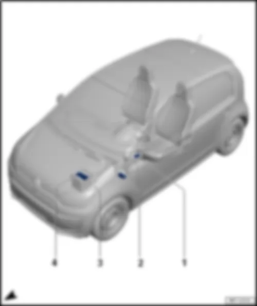
VW UP 2012 Overview of fuse holder
Overview of fuse holder1 - | Fuse holder D -SD- |
q | Only models with start/stop system |
q | Fitting location → Chapter |
q | Fuse assignment, from August 2011 → Chapter |
q | Fuse assignment from May 2013 → Chapter |
2 - | Fuse holder C -SC- |
q | Fitting location left-hand drive → Chapter |
q | Fitting location right-hand drive → Chapter |
q | Fuse assignment, from August 2011 → Chapter |
q | Fuse assignment from May 2013 → Chapter |
q | Fuse assignment from November 2014 → Chapter |
3 - | Fuse holder B -SB- |
q | Fitting location → Chapter |
q | Fuse assignment, from August 2011 → Chapter |
q | Fuse assignment from May 2013 → Chapter |
4 - | Fuse holder A -SA- |
q | Fitting location → Chapter |
q | Fuse assignment, from August 2011 → Chapter |
q | Fuse assignment from May 2013 → Chapter |
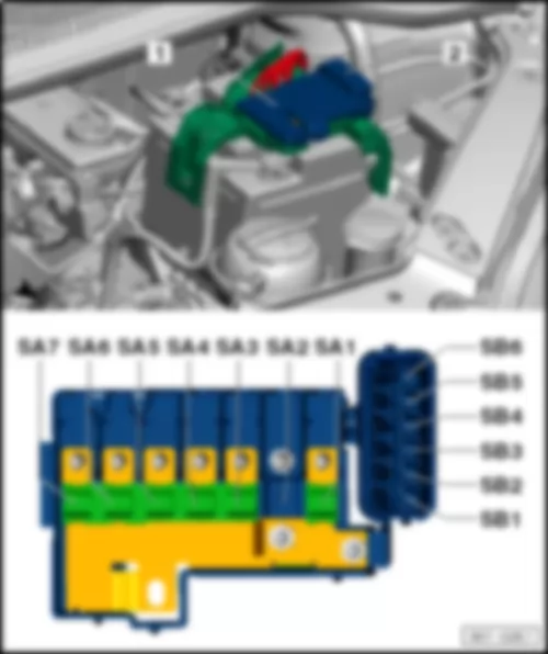
VW UP 2012 Fitting location fuse holder A SA
|
1 - | Fuse holder A (SA) |
⇒ Electrical system, Repair Group 97, Removing and installing fuse holders |
Multifuse strip fuse |
Note
The strip fuse (Multifuse) must be replaced as a complete unit. |
Back to overview → Chapter |
VW UP 2012
Fuse assignment fuse holder A -SA- , from August 2011 |
No. | Current Flow Diagram designation | Nominal value | Function/component | Terminal | |
SA1 | B1 | Fuse 1 on fuse holder A -SA1- | 150 A 175 A 2 | Alternator -C- | 30 |
SA2 | C1 | ||||
SA3 | D1 | Fuse 3 on fuse holder A -SA3- | 110A | Fuse holder C -SC- | 30 |
Main relay -J271- | |||||
Terminal 75 voltage supply relay 1 -J680- | |||||
SA4 | E1 | Fuse 4 on fuse holder A -SA4- | 40A | Power steering control unit -J500- | 30 |
SA5 | F1 | Fuse 5 on fuse holder A -SA5- | 40A | ABS control unit -J104- | 30 |
SA6 | G1 | Fuse 6 on fuse holder A -SA6- | 40A | Radiator fan control unit -J293- | 30 |
SA7 | H1 | Fuse 7 on fuse holder A -SA7- | 50A | Automated manual gearbox control unit -J514-1 | 30 |
1 Depends on equipment |
2 Only models with start/stop system |
Back to overview → Chapter |
VW UP 2012
Fuse assignment fuse holder A -SA- , from May 2013 |
No. | Current Flow Diagram designation | Nominal value | Function/component | Terminal | |
SA1 | B1 | Fuse 1 on fuse holder A -SA1- | 150 A 175 A 2 | Alternator -C- | 30 |
SA2 | C1 | Fuse 2 on fuse holder A -SA2- | 30A | Amplifier -R12- | 30 |
SA3 | D1 | Fuse 3 on fuse holder A -SA3- | 110A | Fuse holder C -SC- | 30 |
Main relay -J271- | |||||
Terminal 75 voltage supply relay 1 -J680- | |||||
SA4 | E1 | Fuse 4 on fuse holder A -SA4- | 50A | Power steering control unit -J500- | 30 |
SA5 | F1 | Fuse 5 on fuse holder A -SA5- | 40A | ABS control unit -J104- | 30 |
SA6 | G1 | Fuse 6 on fuse holder A -SA6- | 40A | Radiator fan control unit -J293- | 30 |
SA7 | H1 | Fuse 7 on fuse holder A -SA7- | 50A | Automated manual gearbox control unit -J514-1 | 30 |
1 Depends on equipment |
2 Only models with start/stop system |
Back to overview → Chapter |
VW UP 2012 Fitting location fuse holder B SB
|
2 - | Fuse holder B (SB) |
- | Fuse colours |
50A - red |
40A - orange |
30A - light-green |
25A - natural (white) |
20A - yellow |
15A - light blue |
10A - red |
7.5A - brown |
5A - light-brown |
3 A - violet |
Back to overview → Chapter |
VW UP 2012
Fuse assignment fuse holder B -SB- , from August 2011 |
No. | Current Flow Diagram designation | Nominal value | Function/component | Terminal | |||
SB1 | J1 | Fuse 1 on fuse holder B -SB1- | 25A | ABS control unit -J104- | 30 | ||
SB2 | J2 | Fuse 2 on fuse holder B -SB2- | 30A | Radiator fan thermal switch -F18- | 30 | ||
Radiator fan control unit -J293- | |||||||
SB3 | J3 | Fuse 3 on fuse holder B -SB3- | 5A | Radiator fan control unit -J293- | 30 | ||
Terminal S ignition/starter switch -D- | |||||||
SB4 | J4 | Fuse 4 on fuse holder B -SB4- | 10A | ABS control unit -J104- | 30 | ||
SB5 | J5 | Fuse 5 on fuse holder B -SB5- | 5A | Onboard supply control unit -J519- | 30 | ||
| |||||||
SB6 | J6 | Fuse 6 on fuse holder B -SB6- | 30A | Fuse holder C -SC- Ignition/starter switch -D- | 30 |
|
VW UP 2012
Fuse assignment fuse holder B -SB- , from May 2013 |
No. | Current Flow Diagram designation | Nominal value | Function/component | Terminal | |||
SB1 | J1 | Fuse 1 on fuse holder B -SB1- | 30A | ABS control unit -J104- | 30 | ||
SB2 | J2 | Fuse 2 on fuse holder B -SB2- | 30A | Radiator fan thermal switch -F18- | 30 | ||
Radiator fan control unit -J293- | |||||||
SB3 | J3 | Fuse 3 on fuse holder B -SB3- | 7.5 A | Radiator fan control unit -J293- | 30 | ||
Terminal S ignition/starter switch -D- | |||||||
SB4 | J4 | Fuse 4 on fuse holder B -SB4- | 10A | ABS control unit -J104- | 30 | ||
SB5 | J5 | Fuse 5 on fuse holder B -SB5- | 7.5 A | Onboard supply control unit -J519- | 30 | ||
| |||||||
SB6 | J6 | Fuse 6 on fuse holder B -SB6- | 30A | Fuse holder C -SC- Ignition/starter switch -D- | 30 |
|
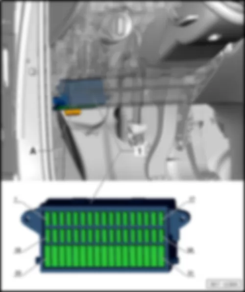
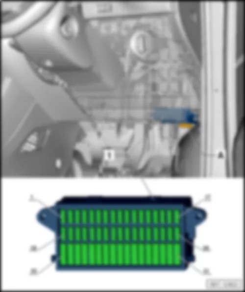
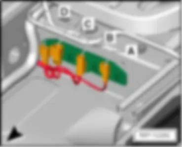
VW UP 2012 Fuse holder C SC
Fuse holder C -SC- |
Fitting location fuse holder C -SC- , left-hand drive models |
1 - | Fuse holder C -SC- |
- | Fuse colours |
50A - red |
40A - orange |
30A - light-green |
25A - natural (white) |
20A - yellow |
15A - light blue |
10A - red |
7.5A - brown |
5A - light-brown |
3 A - violet |
|
Fitting location fuse holder C -SC- , right-hand drive models |
- | Fuse holder C -SC- |
- | Fuse colours |
50A - red |
40A - orange |
30A - light-green |
25A - natural (white) |
20A - yellow |
15A - light blue |
10A - red |
7.5A - brown |
5A - light-brown |
3 A - violet |
|
Fuse assignment fuse holder C -SC- , from August 2011 |
No. | Current Flow Diagram designation | Nominal value | Function/component | Terminal | |||||||
1 | - | Fuse 1 on fuse holder C -SC1- | 5A | Dash panel insert -K- | 15 | ||||||
Engine control unit -J623- | |||||||||||
Radiator fan control unit -J293- | |||||||||||
2 | - | Fuse 2 on fuse holder C -SC2- | 15A | Air conditioning system relay -J32- | 15 | ||||||
Air conditioning system control unit -J301- | |||||||||||
Diagnostic connection -U31- | |||||||||||
High-pressure sender -G65- | |||||||||||
3 | - | Fuse 3 on fuse holder C -SC3- | 7.5A | Brake light switch -F- | 87 | ||||||
Clutch pedal switch -F36- | |||||||||||
Camshaft control valve 1 -N205- | |||||||||||
4 | - | Fuse 4 on fuse holder C -SC4- | 7.5A | Onboard supply control unit -J519- | 58 | ||||||
| |||||||||||
5 | - | Fuse 5 on fuse holder C -SC5- | 5A | Onboard supply control unit -J519-
| 15 | ||||||
CCS switch -E45- | |||||||||||
6 | - | Fuse 6 on fuse holder C -SC6- | 5A | Headlight range control regulator -E102- | 15 | ||||||
Left headlight range control motor -V48- | |||||||||||
Right headlight range control motor -V49- | |||||||||||
Mirror adjustment switch -E43- | |||||||||||
7 | - | Fuse 7 on fuse holder C -SC7- | 10A | Selector lever -E313- | 30 | ||||||
8 | - | Fuse 8 on fuse holder C -SC8- | 7.5A | Automated manual gearbox control unit -J514- | 15 | ||||||
Selector lever -E313- | |||||||||||
9 | - | Fuse 9 on fuse holder C -SC9- | 7.5A | Airbag control unit -J234- | 15 | ||||||
Centre switch module 2 in dash panel -EX35- | |||||||||||
10 | - | Fuse 10 on fuse holder C -SC10- | 5A | Parking aid control unit -J446- | 15 | ||||||
11 | - | Fuse 11 on fuse holder C -SC11- | 10A | Right headlight dipped beam bulb -M31- | 56b | ||||||
12 | - | Fuse 12 on fuse holder C -SC12- | 5A | Dash panel insert -K- | 75 | ||||||
Rear left fog light bulb -L46- | |||||||||||
13 | - | Fuse 13 on fuse holder C -SC13- | 10A | Left headlight dipped beam bulb -M29- | 56b | ||||||
14 | - | Fuse 14 on fuse holder C -SC14- | 15A | Rear window wiper motor -V12- | 75 | ||||||
15 | - | Fuse 15 on fuse holder C -SC15- | 15A | Light switch -E1- | 30 | ||||||
16 | - | Fuse 16 on fuse holder C -SC16- | 5A | Terminal 15 voltage supply relay -J329- | 15 | ||||||
Power steering control unit -J500- | |||||||||||
17 | - | Fuse 17 on fuse holder C -SC17- | 15A | Washer pump switch (automatic wash/wipe and headlight washer system) -E44- | 15 | ||||||
18 | - | Fuse 18 on fuse holder C -SC18- | 7.5A | Reversing light switch -F4- | 30 | ||||||
19 | - | Fuse 19 on fuse holder C -SC19- | 15A | Injector, cylinder 1 -N30- | 87 | ||||||
Injector, cylinder 2 -N31- | |||||||||||
Injector, cylinder 3 -N32- | |||||||||||
20 | - | Fuse 20 on fuse holder C -SC20- | 5A | ABS control unit -J104- | 15 | ||||||
Emergency braking function sensor unit -J939- | |||||||||||
Steering angle sender -G85- | |||||||||||
21 | - | Fuse 21 on fuse holder C -SC21- | 5A | Right side light bulb -M3- | 58 | ||||||
Right tail light bulb -M2- | |||||||||||
Number plate light -X- | |||||||||||
Onboard supply control unit -J519- | |||||||||||
| |||||||||||
22 | - | Fuse 22 on fuse holder C -SC22- | 10A | Left daytime running light bulb -L174- | 58 | ||||||
Right daytime running light bulb -L175- | |||||||||||
23 | - | Fuse 23 on fuse holder C -SC23- | 5A | Left side light bulb -M1- | 58 | ||||||
Left tail light bulb -M4- | |||||||||||
24 | - | Fuse 24 on fuse holder C -SC24- | 15A | Headlight flasher switch -E5- | 30 | ||||||
25 | - | Fuse 25 on fuse holder C -SC25- | 10A | Windscreen and rear window washer pump -V59- | 53c | ||||||
26 | - | Fuse 26 on fuse holder C -SC26- | 5A | Main relay -J271- | 30 | ||||||
Dash panel insert -K- | |||||||||||
Steering angle sender -G85- | |||||||||||
27 | - | Fuse 27 on fuse holder C -SC27- | 7.5A | Onboard supply control unit -J519- | 30 | ||||||
| |||||||||||
28 | - | Fuse 28 on fuse holder C -SC28- | 5A | Diagnostic connection -U31- | 30 | ||||||
29 | - | Fuse 29 on fuse holder C -SC29- | 7.5A | Onboard supply control unit -J519- | 30 | ||||||
30 | - | Fuse 30 on fuse holder C -SC30- | 5A | Onboard supply control unit -J519- | 30 | ||||||
| |||||||||||
31 | - | Fuse 31 on fuse holder C -SC31- | 10A | Lambda probe -G39- | 87 | ||||||
Lambda probe after catalytic converter -G130- | |||||||||||
Activated charcoal filter solenoid valve 1 -N80- | |||||||||||
32 | - | Fuse 32 on fuse holder C -SC32- | 15A | Onboard supply control unit -J519- | 30 | ||||||
| |||||||||||
33 | - | Fuse 33 on fuse holder C -SC33- | 10A | Right headlight main beam bulb -M32- | 56a | ||||||
34 | - | Fuse 34 on fuse holder C -SC34- | 10A | Left headlight main beam bulb -M30- | 56a | ||||||
Dash panel insert -K- | |||||||||||
35 | - | Fuse 35 on fuse holder C -SC35- | |||||||||
36 | - | Fuse 36 on fuse holder C -SC36- | 15A | Cigarette lighter -U1- | 75 | ||||||
37 | - | Fuse 37 on fuse holder C -SC37- | 30A | Air conditioning system control unit -J301- | 75 | ||||||
Heater control unit -J162- | |||||||||||
38 | - | Fuse 38 on fuse holder C -SC38- | 15A | Radio -R- | 30 | ||||||
39 | - | Fuse 39 on fuse holder C -SC39- | 30A | Sliding sunroof adjustment control unit -J245- | 30 | ||||||
40 | - | Fuse 40 on fuse holder C -SC40- | 15A | Engine control unit -J623- | 87 | ||||||
41 | - | Fuse 41 on fuse holder C -SC41- | 25A | Onboard supply control unit -J519- | 30 | ||||||
| |||||||||||
42 | - | Fuse 42 on fuse holder C -SC42- | 25A | Ignition coil 1 with output stage -N70- | 87 | ||||||
Ignition coil 2 with output stage -N127- | |||||||||||
Ignition coil 3 with output stage -N291- | |||||||||||
43 | - | Fuse 43 on fuse holder C -SC43- | 20A | Heated front seats control unit -J774- | 75 | ||||||
Switch module in centre of dash panel -EX22- | |||||||||||
Centre switch module 2 in dash panel -EX35- | |||||||||||
44 | - | Fuse 44 on fuse holder C -SC44- | 15A | Fuel pump relay -J17- | 30 | ||||||
45 | - | Fuse 45 on fuse holder C -SC45- | 20A | Light switch -E1- | 15 | ||||||
46 | - | Fuse 46 on fuse holder C -SC46- | 30A | Onboard supply control unit -J519- | 30 | ||||||
| |||||||||||
47 | - | Fuse 47 on fuse holder C -SC47- | 25A | Front right window regulator switch -E41- | 15 | ||||||
48 | - | Fuse 48 on fuse holder C -SC48- | 20A | Onboard supply control unit -J519- | 30 | ||||||
| |||||||||||
49 | - | Fuse 49 on fuse holder C -SC49- | 20A | Onboard supply control unit -J519- | 30 | ||||||
| |||||||||||
50 | - | Fuse 50 on fuse holder C -SC50- | 15A | Left fog light bulb -L22- | 55 | ||||||
Right fog light bulb -L23- | |||||||||||
51 | - | Fuse 51 on fuse holder C -SC51- | 25A | Front left window regulator switch -E40- | 15 |
|
Fuse assignment fuse holder C -SC- , from May 2013 |
No. | Current Flow Diagram designation | Nominal value | Function/component | Terminal | |||||||
1 | - | Fuse 1 on fuse holder C -SC1- | 7.5A | Dash panel insert -K- | 15 | ||||||
Engine control unit -J623- | |||||||||||
Radiator fan control unit -J293- | |||||||||||
2 | - | Fuse 2 on fuse holder C -SC2- | 15A | Air conditioning system relay -J32- | 15 | ||||||
Air conditioning system control unit -J301- | |||||||||||
Diagnostic connection -U31- | |||||||||||
High-pressure sender -G65- | |||||||||||
3 | - | Fuse 3 on fuse holder C -SC3- | 7.5A | Brake light switch -F- | 87 | ||||||
Clutch pedal switch -F36- | |||||||||||
Camshaft control valve 1 -N205- | |||||||||||
4 | - | Fuse 4 on fuse holder C -SC4- | 7.5A | Onboard supply control unit -J519- | 58 | ||||||
| |||||||||||
5 | - | Fuse 5 on fuse holder C -SC5- | 7.5A | Onboard supply control unit -J519-
| 15 | ||||||
CCS switch -E45- | |||||||||||
6 | - | Fuse 6 on fuse holder C -SC6- | 7.5A | Headlight range control regulator -E102- | 15 | ||||||
Left headlight range control motor -V48- | |||||||||||
Right headlight range control motor -V49- | |||||||||||
Mirror adjustment switch -E43- | |||||||||||
7 | - | Fuse 7 on fuse holder C -SC7- | 10A | Selector lever -E313- | 30 | ||||||
8 | - | Fuse 8 on fuse holder C -SC8- | 7.5A | Automated manual gearbox control unit -J514- | 15 | ||||||
Selector lever -E313- | |||||||||||
9 | - | Fuse 9 on fuse holder C -SC9- | 7.5A | Airbag control unit -J234- | 15 | ||||||
Centre switch module 2 in dash panel -EX35- | |||||||||||
10 | - | Fuse 10 on fuse holder C -SC10- | 7.5A | Parking aid control unit -J446- | 15 | ||||||
11 | - | Fuse 11 on fuse holder C -SC11- | 10A | Right headlight dipped beam bulb -M31- | 56b | ||||||
12 | - | Fuse 12 on fuse holder C -SC12- | 7.5A | Dash panel insert -K- | 55a | ||||||
Control unit in dash panel insert -J285- | |||||||||||
Rear left fog light bulb -L46- | |||||||||||
Onboard supply control unit -J519- | |||||||||||
13 | - | Fuse 13 on fuse holder C -SC13- | 10A | Left headlight dipped beam bulb -M29- | 56b | ||||||
14 | - | Fuse 14 on fuse holder C -SC14- | 15A | Rear window wiper motor -V12- | 75 | ||||||
15 | - | Fuse 15 on fuse holder C -SC15- | 15A | Light switch -E1- | 30 | ||||||
16 | - | Fuse 16 on fuse holder C -SC16- | 7.5A | Terminal 15 voltage supply relay -J329- | 15 | ||||||
Power steering control unit -J500- | |||||||||||
17 | - | Fuse 17 on fuse holder C -SC17- | 15A | Washer pump switch (automatic wash/wipe and headlight washer system) -E44- | 15 | ||||||
18 | - | Fuse 18 on fuse holder C -SC18- | 7.5A | Reversing light switch -F4- | 15 | ||||||
19 | - | Fuse 19 on fuse holder C -SC19- | 15A | Injector, cylinder 1 -N30- | 87 | ||||||
Injector, cylinder 2 -N31- | |||||||||||
Injector, cylinder 3 -N32- | |||||||||||
20 | - | Fuse 20 on fuse holder C -SC20- | 7.5A | ABS control unit -J104- | 15 | ||||||
Emergency braking function sensor unit -J939- | |||||||||||
Steering angle sender -G85- | |||||||||||
21 | - | Fuse 21 on fuse holder C -SC21- | 7.5A | Right side light bulb -M3- | 58 | ||||||
Right tail light bulb -M2- | |||||||||||
Number plate light -X- | |||||||||||
Onboard supply control unit -J519- | |||||||||||
| |||||||||||
22 | - | Fuse 22 on fuse holder C -SC22- | 10A | Left daytime running light bulb -L174- | 58 | ||||||
Right daytime running light bulb -L175- | |||||||||||
23 | - | Fuse 23 on fuse holder C -SC23- | 7.5A | Left side light bulb -M1- | 58 | ||||||
Left tail light bulb -M4- | |||||||||||
24 | - | Fuse 24 on fuse holder C -SC24- | 15A | Headlight flasher switch -E5- | 30 | ||||||
25 | - | Fuse 25 on fuse holder C -SC25- | 10A | Windscreen and rear window washer pump -V59- | 53c | ||||||
26 | - | Fuse 26 on fuse holder C -SC26- | 7.5A | Main relay -J271- | 30 | ||||||
Dash panel insert -K- | |||||||||||
Steering angle sender -G85- | |||||||||||
27 | - | Fuse 27 on fuse holder C -SC27- | 7.5A | Onboard supply control unit -J519- | 30 | ||||||
| |||||||||||
28 | - | Fuse 28 on fuse holder C -SC28- | 7.5A | Diagnostic connection -U31- | 30 | ||||||
29 | - | Fuse 29 on fuse holder C -SC29- | 7.5A | Onboard supply control unit -J519- | 30 | ||||||
30 | - | Fuse 30 on fuse holder C -SC30- | 7.5A | Onboard supply control unit -J519- | 30 | ||||||
| |||||||||||
31 | - | Fuse 31 on fuse holder C -SC31- | 10A | Lambda probe -G39- | 87 | ||||||
Lambda probe after catalytic converter -G130- | |||||||||||
Activated charcoal filter solenoid valve 1 -N80- | |||||||||||
32 | - | Fuse 32 on fuse holder C -SC32- | 15A | Onboard supply control unit -J519- | 30 | ||||||
| |||||||||||
33 | - | Fuse 33 on fuse holder C -SC33- | 10A | Right headlight main beam bulb -M32- | 56a | ||||||
34 | - | Fuse 34 on fuse holder C -SC34- | 10A | Left headlight main beam bulb -M30- | 56a | ||||||
Dash panel insert -K- | |||||||||||
35 | - | Fuse 35 on fuse holder C -SC35- | |||||||||
36 | - | Fuse 36 on fuse holder C -SC36- | 20A | Cigarette lighter -U1- | 75 | ||||||
37 | - | Fuse 37 on fuse holder C -SC37- | 30A | Air conditioning system control unit -J301- | 75 | ||||||
Heater control unit -J162- | |||||||||||
38 | - | Fuse 38 on fuse holder C -SC38- | 15A | Radio -R- | 30 | ||||||
39 | - | Fuse 39 on fuse holder C -SC39- | 30A | Sliding sunroof adjustment control unit -J245- | 30 | ||||||
40 | - | Fuse 40 on fuse holder C -SC40- | 15A | Engine control unit -J623- | 87 | ||||||
41 | - | Fuse 41 on fuse holder C -SC41- | 25A | Onboard supply control unit -J519- | 30 | ||||||
| |||||||||||
42 | - | Fuse 42 on fuse holder C -SC42- | 25A | Ignition coil 1 with output stage -N70- | 87 | ||||||
Ignition coil 2 with output stage -N127- | |||||||||||
Ignition coil 3 with output stage -N291- | |||||||||||
43 | - | Fuse 43 on fuse holder C -SC43- | 20A | Heated front seats control unit -J774- | 75 | ||||||
Switch module in centre of dash panel -EX22- | |||||||||||
Centre switch module 2 in dash panel -EX35- | |||||||||||
44 | - | Fuse 44 on fuse holder C -SC44- | 15A | Fuel pump relay -J17- | 30 | ||||||
45 | - | Fuse 45 on fuse holder C -SC45- | 20A | Light switch -E1- | 15 | ||||||
46 | - | Fuse 46 on fuse holder C -SC46- | 30A | Onboard supply control unit -J519- | 30 | ||||||
| |||||||||||
47 | - | Fuse 47 on fuse holder C -SC47- | 30A | Front right window regulator switch -E41- | 15 | ||||||
48 | - | Fuse 48 on fuse holder C -SC48- | 20A | Onboard supply control unit -J519- | 30 | ||||||
| |||||||||||
49 | - | Fuse 49 on fuse holder C -SC49- | 30A | Onboard supply control unit -J519- | 30 | ||||||
| |||||||||||
50 | - | Fuse 50 on fuse holder C -SC50- | 15A | Left fog light bulb -L22- | 55 | ||||||
Right fog light bulb -L23- | |||||||||||
20A1 | Onboard supply control unit -J519-1 | ||||||||||
51 | - | Fuse 51 on fuse holder C -SC51- | 30A | Front left window regulator switch -E40- | 15 |
|
Fuse assignment fuse holder C -SC- , from November 2014 |
No. | Current Flow Diagram designation | Nominal value | Function/component | Terminal | |||||||
1 | - | Fuse 1 on fuse holder C -SC1- | 7.5A | Dash panel insert -K- | 15 | ||||||
Engine control unit -J623- | |||||||||||
Radiator fan control unit -J293- | |||||||||||
2 | - | Fuse 2 on fuse holder C -SC2- | 15A | Air conditioning system relay -J32- | 15 | ||||||
Air conditioning system control unit -J301- | |||||||||||
Diagnostic connection -U31- | |||||||||||
High-pressure sender -G65- | |||||||||||
3 | - | Fuse 3 on fuse holder C -SC3- | 7.5A | Brake light switch -F- | 87 | ||||||
Clutch pedal switch -F36- | |||||||||||
Camshaft control valve 1 -N205- | |||||||||||
4 | - | Fuse 4 on fuse holder C -SC4- | 7.5A | Onboard supply control unit -J519- | 58 | ||||||
| |||||||||||
5 | - | Fuse 5 on fuse holder C -SC5- | 7.5A | Onboard supply control unit -J519-
| 15 | ||||||
CCS switch -E45- | |||||||||||
6 | - | Fuse 6 on fuse holder C -SC6- | 7.5A | Headlight range control regulator -E102- | 15 | ||||||
Left headlight range control motor -V48- | |||||||||||
Right headlight range control motor -V49- | |||||||||||
Mirror adjustment switch -E43- | |||||||||||
7 | - | Fuse 7 on fuse holder C -SC7- | 10A | Selector lever -E313- | 30 | ||||||
8 | - | Fuse 8 on fuse holder C -SC8- | 7.5A | Automated manual gearbox control unit -J514- | 15 | ||||||
Selector lever -E313- | |||||||||||
9 | - | Fuse 9 on fuse holder C -SC9- | 7.5A | Airbag control unit -J234- | 15 | ||||||
Centre switch module 2 in dash panel -EX35- | |||||||||||
10 | - | Fuse 10 on fuse holder C -SC10- | 7.5A | Parking aid control unit -J446- | 15 | ||||||
11 | - | Fuse 11 on fuse holder C -SC11- | 10A | Right headlight dipped beam bulb -M31- | 56b | ||||||
12 | - | Fuse 12 on fuse holder C -SC12- | 7.5A | Dash panel insert -K- | 55a | ||||||
Control unit in dash panel insert -J285- | |||||||||||
Rear left fog light bulb -L46- | |||||||||||
Onboard supply control unit -J519- | |||||||||||
13 | - | Fuse 13 on fuse holder C -SC13- | 10A | Left headlight dipped beam bulb -M29- | 56b | ||||||
14 | - | Fuse 14 on fuse holder C -SC14- | 15A | Rear window wiper motor -V12- | 75 | ||||||
15 | - | Fuse 15 on fuse holder C -SC15- | 15A | Light switch -E1- | 30 | ||||||
16 | - | Fuse 16 on fuse holder C -SC16- | 7.5A | Terminal 15 voltage supply relay -J329- | 15 | ||||||
Power steering control unit -J500- | |||||||||||
17 | - | Fuse 17 on fuse holder C -SC17- | 15A | Washer pump switch (automatic wash/wipe and headlight washer system) -E44- | 15 | ||||||
18 | - | Fuse 18 on fuse holder C -SC18- | 7.5A | Reversing light switch -F4- | 15 | ||||||
19 | - | Fuse 19 on fuse holder C -SC19- | 15A | Injector, cylinder 1 -N30- | 87 | ||||||
Injector, cylinder 2 -N31- | |||||||||||
Injector, cylinder 3 -N32- | |||||||||||
20 | - | Fuse 20 on fuse holder C -SC20- | 7.5A | ABS control unit -J104- | 15 | ||||||
Emergency braking function sensor unit -J939- | |||||||||||
Steering angle sender -G85- | |||||||||||
21 | - | Fuse 21 on fuse holder C -SC21- | 7.5A | Right side light bulb -M3- | 58 | ||||||
Right tail light bulb -M2- | |||||||||||
Number plate light -X- | |||||||||||
Onboard supply control unit -J519- | |||||||||||
| |||||||||||
22 | - | Fuse 22 on fuse holder C -SC22- | 10A | Left daytime running light bulb -L174- | 58 | ||||||
Right daytime running light bulb -L175- | |||||||||||
23 | - | Fuse 23 on fuse holder C -SC23- | 7.5A | Left side light bulb -M1- | 58 | ||||||
Left tail light bulb -M4- | |||||||||||
24 | - | Fuse 24 on fuse holder C -SC24- | 15A | Headlight flasher switch -E5- | 30 | ||||||
25 | - | Fuse 25 on fuse holder C -SC25- | 10A | Windscreen and rear window washer pump -V59- | 53c | ||||||
26 | - | Fuse 26 on fuse holder C -SC26- | 7.5A | Main relay -J271- | 30 | ||||||
Dash panel insert -K- | |||||||||||
Steering angle sender -G85- | |||||||||||
27 | - | Fuse 27 on fuse holder C -SC27- | 7.5A | Onboard supply control unit -J519- | 30 | ||||||
| |||||||||||
28 | - | Fuse 28 on fuse holder C -SC28- | 7.5A | Diagnostic connection -U31- | 30 | ||||||
29 | - | Fuse 29 on fuse holder C -SC29- | 7.5A | Onboard supply control unit -J519- | 30 | ||||||
30 | - | Fuse 30 on fuse holder C -SC30- | 7.5A | Onboard supply control unit -J519- | 30 | ||||||
| |||||||||||
31 | - | Fuse 31 on fuse holder C -SC31- | 10A | Lambda probe -G39- | 87 | ||||||
Lambda probe after catalytic converter -G130- | |||||||||||
Activated charcoal filter solenoid valve 1 -N80- | |||||||||||
32 | - | Fuse 32 on fuse holder C -SC32- | 15A | Onboard supply control unit -J519- | 30 | ||||||
| |||||||||||
33 | - | Fuse 33 on fuse holder C -SC33- | 10A | Right headlight main beam bulb -M32- | 56a | ||||||
34 | - | Fuse 34 on fuse holder C -SC34- | 10A | Left headlight main beam bulb -M30- | 56a | ||||||
Dash panel insert -K- | |||||||||||
35 | - | Fuse 35 on fuse holder C -SC35- | |||||||||
36 | - | Fuse 36 on fuse holder C -SC36- | 20A | Cigarette lighter -U1- | 75 | ||||||
37 | - | Fuse 37 on fuse holder C -SC37- | 30A | Air conditioning system control unit -J301- | 75 | ||||||
Heater control unit -J162- | |||||||||||
38 | - | Fuse 38 on fuse holder C -SC38- | 15A | Radio -R- | 30 | ||||||
39 | - | Fuse 39 on fuse holder C -SC39- | 30A | Sliding sunroof adjustment control unit -J245- | 30 | ||||||
40 | - | Fuse 40 on fuse holder C -SC40- | 15A | Engine control unit -J623- | 87 | ||||||
41 | - | Fuse 41 on fuse holder C -SC41- | 25A | Onboard supply control unit -J519- | 30 | ||||||
| |||||||||||
42 | - | Fuse 42 on fuse holder C -SC42- | 25A | Ignition coil 1 with output stage -N70- | 87 | ||||||
Ignition coil 2 with output stage -N127- | |||||||||||
Ignition coil 3 with output stage -N291- | |||||||||||
43 | - | Fuse 43 on fuse holder C -SC43- | 20A | Heated front seats control unit -J774- | 75 | ||||||
Switch module in centre of dash panel -EX22- | |||||||||||
Centre switch module 2 in dash panel -EX35- | |||||||||||
44 | - | Fuse 44 on fuse holder C -SC44- | 15A | Fuel pump relay -J17- | 30 | ||||||
45 | - | Fuse 45 on fuse holder C -SC45- | 20A | Light switch -E1- | 15 | ||||||
46 | - | Fuse 46 on fuse holder C -SC46- | 30A | Onboard supply control unit -J519- | 30 | ||||||
| |||||||||||
47 | - | Fuse 47 on fuse holder C -SC47- | 30A | Front right window regulator switch -E41- Operating unit for window regulator in driver door -E512-2 Driver side central locking lock unit -F220- | 15 | ||||||
48 | - | Fuse 48 on fuse holder C -SC48- | 20A | Onboard supply control unit -J519- | 30 | ||||||
| |||||||||||
49 | - | Fuse 49 on fuse holder C -SC49- | 30A | Onboard supply control unit -J519- | 30 | ||||||
| |||||||||||
50 | - | Fuse 50 on fuse holder C -SC50- | 15A | Left fog light bulb -L22- | 55 | ||||||
Right fog light bulb -L23- | |||||||||||
20A1 | Onboard supply control unit -J519-1 | ||||||||||
51 | - | Fuse 51 on fuse holder C -SC51- | 30A | Operating unit for window regulator in driver door -E512- Driver side central locking lock unit -F220-2 | 15 |
|
Fuse holder D -SD- |
Fitting location fuse holder D -SD- , left-hand drive models |
A - | Fuse holder D -SD- |
q | Only models with start/stop system |
- | Fuse colours |
50A - red |
40A - orange |
30A - light-green |
25A - natural (white) |
20A - yellow |
15A - light blue |
10A - red |
7.5A - brown |
5A - light-brown |
3 A - violet |
Back to overview → Chapter |
Fuse assignment on fuse holder D -SD- , from August 2011 |
No. | Current Flow Diagram designation | Nominal value | Function/component | Terminal | |||
SD1 | Fuse 1 on fuse holder D -SD1- | 5A | Emergency braking function sensor unit -J939- | 30 | |||
SD2 | Fuse 2 on fuse holder D -SD2- | 5A | Dash panel insert -K- | 30 | |||
SD3 | Fuse 3 on fuse holder D -SD3- | 10A | Radio -R- | 30 | |||
SD4 | Fuse 4 on fuse holder D -SD4- | 7.5 A | Voltage converter -A19- Starter relay 1 -J906- Starter relay 2 -J907- | 15 | |||
SD5 | |||||||
SD6 | |||||||
SD7 | |||||||
SD8 | |||||||
SD9 | Fuse 9 on fuse holder D -SD9- | 15A | Onboard supply control unit -J519-
| 30 | |||
SD10 | Fuse 10 on fuse holder D -SD10- | 15A | Onboard supply control unit -J519-
| 30 | |||
SD11 | Fuse 11 on fuse holder D -SD11- | 30A | Starter relay 1 -J906- Starter relay 2 -J907- | 30 | |||
SD12 | Fuse 12 on fuse holder D -SD12- | 30A | Voltage converter -A19- | 30 |
|
Fuse assignment on fuse holder D -SD- , from May 2013 |
No. | Current Flow Diagram designation | Nominal value | Function/component | Terminal | |||
SD1 | Fuse 1 on fuse holder D -SD1- | 7.5A | Relay for emergency braking function -J1020- Emergency braking function sensor unit -J939- | 30 | |||
SD2 | Fuse 2 on fuse holder D -SD2- | 7.5A | Dash panel insert -K- | 30 | |||
SD3 | Fuse 3 on fuse holder D -SD3- | 15A | Radio -R- | 30 | |||
SD4 | Fuse 4 on fuse holder D -SD4- | 7.5 A | Voltage converter -A19- Starter relay 1 -J906- Starter relay 2 -J907- | 15 | |||
SD5 | |||||||
SD6 | |||||||
SD7 | |||||||
SD8 | |||||||
SD9 | Fuse 9 on fuse holder D -SD9- | 15A | Onboard supply control unit -J519-
| 30 | |||
SD10 | Fuse 10 on fuse holder D -SD10- | 15A | Onboard supply control unit -J519-
| 30 | |||
SD11 | Fuse 11 on fuse holder D -SD11- | 30A | Starter relay 1 -J906- Starter relay 2 -J907- | 30 | |||
SD12 | Fuse 12 on fuse holder D -SD12- | 30A | Voltage converter -A19- | 30 |
|
VW UP 2012 Overview of coupling stations and connectors
Overview of coupling stations and connectors Note:
Note figure shows right-hand drive model. The location of the connectors on a left-hand drive model are identical. |
1 - | Electronic manual gearbox control unit -T14a-, -T14b- |
q | Fitting location → Chapter |
2 - | Coupling station, accelerator -T6p-, 1 |
q | Fitting location → Chapter |
3 - | Coupling station on right A-pillar -T28a- |
q | Fitting location → Chapter |
4 - | Coupling station for exterior mirror, in front right door -T5e- |
q | Fitting location → Chapter |
5 - | Diagnosis connection, -U31-, -T16f- |
q | Location for models with left-hand drive → Chapter |
q | Location for models with right-hand drive → Anchor |
6 - | Dash panel centre switch module 2, -EX35-, -T16c- |
q | Fitting location → Chapter |
7 - | Coupling station under front right seat, -T2ao-, -T3m-, -T2ap-, -T2x- |
q | Fitting location → Chapter |
8 - | Coupling station on right B-pillar, -T28c- |
q | Fitting location → Chapter |
9 - | Coupling station for panorama sliding roof, -T2p- |
q | Fitting location → Chapter |
10 - | Coupling station for panorama sliding roof, -T4p- |
q | Fitting location → Chapter |
11 - | Coupling station for CNG tank |
12 - | Coupling station for aerial, -T2bl- |
q | Fitting location → Chapter |
13 - | Parking aid coupling station, on left in rear bumper -T8b- |
q | Fitting location → Chapter |
14 - | Coupling station in rear lid, -T5c-, -T5d- |
q | Fitting location → Chapter |
15 - | Coupling station under front left seat, -T2an-, -T3c-, -T2v-, |
q | Fitting location → Chapter |
16 - | Coupling station on left B-pillar, -T28b- |
q | Fitting location → Chapter |
17 - | Switch module in centre of dash panel, -EX22-, -T8c- |
q | Fitting location → Chapter |
18 - | Dash panel centre switch module, -EX22-, T16b- |
q | Fitting location → Chapter |
19 - | Coupling station in centre of dash panel, -T2bm-, -T2bn-, -J983-, -T12b- |
q | Fitting location → Chapter |
20 - | Coupling station for exterior mirror, in front left door -T8f- |
q | Fitting location → Chapter |
21 - | Coupling station on left A-pillar, -T28- |
q | Fitting location → Chapter |
22 - | Coupling station on heater and air conditioner unit, -T2bh- |
q | Fitting location → Chapter |
23 - | Coupling station on front left in engine compartment, -T4f-, -T14- |
q | Fitting location → Chapter |
24 - | Coupling station for radiator fan, -T3o- |
q | Fitting location → Chapter |
VW UP 2012 Coupling stations for electronic manual gearbox
|
A - | 14-pin connector -T14a- |
B - | 14-pin connector -T14b- |
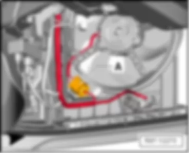
VW UP 2012 Coupling station on heater and air conditioner unit, -T2bh-
|
A - | 2-pin connector, -T2bh- |
VW UP 2012 Coupling station on right A-pillar -T28a-, in front right door -T5e-
|
A - | 28-pin connector -T28a- |
B - | 5-pin connector -T5e- |
VW UP 2012 Coupling station in centre of dash panel, -T2bm-, -T2bn-, -J983-, -T12b-
|
1 - | Aerial connector, -T2bn- |
2 - | 12-pin connector -T12b- |
3 - | Splitter connector, -T2bm- |
4 - | Interface for portable navigation and communication system -J983- |
VW UP 2012 Switch module in centre of dash panel, -EX22-, -EX35-, -T16b-, -T16c-
|
A - | Switch module in centre of dash panel, EX22 |
B - | Switch module 2 in centre of dash panel, -EX35- |
A - | Switch module in centre of dash panel -EX22-, 16-pin connector -T16b- |
B - | Switch module 2 in centre of dash panel, -EX35-, 16-pin connector -T16c- |
VW UP 2012 Coupling station under front right seat, -T2ao-, -T3m-, -T2ap-, -T2x-
|
A - | 2-pin connector for belt switch, -T2ao- |
B - | 3-pin connector for side airbag, -T3m- |
C - | 2-pin connector for seat occupied recognition, -T2ap- |
D - | 2-pin connector for seat heating, -T2x- |
VW UP 2012 Coupling station for panorama sliding roof, -T2p-, -T4p-
|
A - | 2-pin connector -T2p- |
B - | 4-pin connector -T4p- |
VW UP 2012 Coupling station on aerial, -T2bl-
|
- | Aerial connector, -T2bl- |
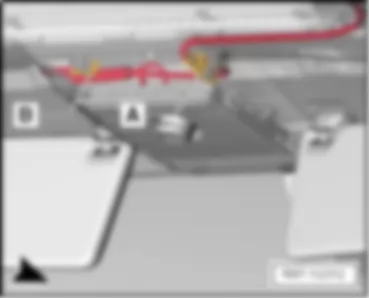
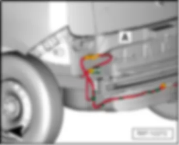
VW UP 2012 Parking aid coupling station, on left in rear bumper -T8b-
|
A - | 8-pin connector -T8b- |
VW UP 2012 Coupling station in rear lid, -T5c-, -T5d-
|
A - | 5-pin connector -T5c- |
B - | 5-pin connector -T5d- |
VW UP 2012 Coupling station under front left seat, -T2an-, -T3c-, -T2v-
|
A - | 2-pin connector for belt switch, -T2a´n- |
B - | 3-pin connector for side airbag, -T3c- |
C - | 2-pin connector for seat heating, -T2v- |
VW UP 2012 Switch module in centre console, -EX22-, -T8c-
|
- | Switch module in centre console -EX22-, 8-pin connector, -T8c- |
VW UP 2012 Diagnosis connection, -U31-, -T16f-
Note:
|
A - | 16-pin connector -T16f- |
Note:
|
A - | 16-pin connector -T16f- |
VW UP 2012 Coupling station on left A-pillar -T28-, in front left door -T8f-
|
A - | 28-pin connector -T28- |
B - | 8-pin connector -T8f- |
VW UP 2012 Coupling station on front left in engine compartment, -T4f-, -T14-
|
A - | Engine connector 1, -T14- |
B - | 4-pin connector for alternator, -T4f- |
VW UP 2012 Coupling station for radiator fan, -T3o-
|
A - | 3-pin connector, -T3o- |
VW UP 2012 Coupling station for accelerator, -T6p- 1
|
A - | 6-pin connector -T6p- |
VW UP 2012 Coupling station on left B-pillar, -T28b-
|
A - | 28-pin connector -T28b- |
VW UP 2012 Coupling station on right B-pillar, -T28c-
|
A - | 28-pin connector -T28c- |
|
VW UP 2012
VW UP 2012 Overview of earth points
Overview of earth points13 | Earth point on right in engine compartment |
q | Fitting location → anchor |
15 | Earth point on cylinder head |
q | Specified torque 9 Nm |
18 | Earth point on cylinder block |
q | Fitting location → anchor |
671 | Earth point 1 on front of left longitudinal member |
q | Fitting location → anchor |
685 | Earth point 1 on front of right longitudinal member |
q | Fitting location → anchor |
764 | Earth point in front left wheel housing |
q | Fitting location → anchor |
1 | Earth strap, battery - body |
q | Fitting location → anchor |
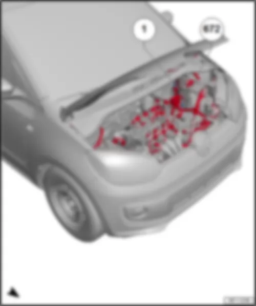
672 | Earth point 2 on front of left longitudinal member |
q | Fitting location → anchor |
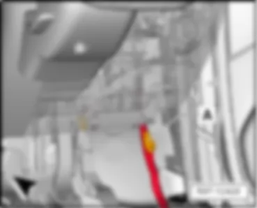
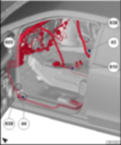
43 | Earth point, lower part of right A-pillar |
q | Fitting location → anchor |
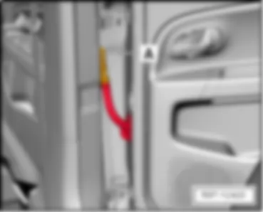
44 | Earth point on lower part of left A-pillar |
q | Fitting location → anchor |
605 | Earth point on top end of steering column |
q | Fitting location → anchor |
610 | Earth point (audio), front below centre console |
q | Fitting location → anchor |
638 | Earth point on right A-pillar |
q | Fitting location → anchor |
639 | Earth point on left A-pillar |
q | Fitting location → anchor |
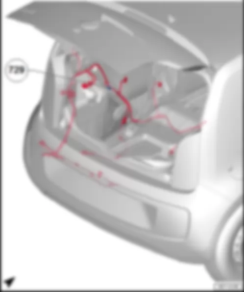
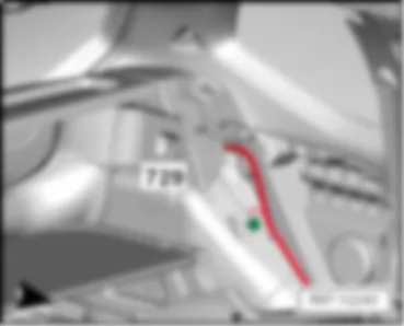
729 | Earth point, on left rear wheel housing |
q | Fitting location → anchor |
VW UP 2012 Earth points, in engine compartment
|
1 | Earth strap, battery - body |
q | Specified torque 20 Nm |
|
13 | Earth point on right in engine compartment |
q | Specified torque 9 Nm |
|
18 | Earth point on cylinder block |
q | Specified torque 20 Nm |
685 | Earth point 1 on front of right longitudinal member |
q | Specified torque 20 Nm |
|
671 | Earth point 1 on front of left longitudinal member |
q | Specified torque 9 Nm |
|
672 | Earth point 2 on front of left longitudinal member |
q | Specified torque 9 Nm |
|
764 | Earth point in front left wheel housing |
q | Specified torque 20 Nm |
VW UP 2012 Overview of earth points in passenger compartment
|
43 | Earth point, lower part of right A-pillar |
q | Specified torque 9 Nm |
638 | Earth point, on right A-pillar1 |
q | Specified torque 9 Nm |
|
44 | Earth point on lower part of left A-pillar |
q | Specified torque 9 Nm |
639 | Earth point, left A-pillar1 |
q | Specified torque 9 Nm |
|
605 | Earth point on top end of steering column |
q | Specified torque 9 Nm |
|
610 | Earth point (audio), front below centre console |
q | Specified torque 9 Nm |
VW UP 2012 Earth points in luggage compartment
|
729 | Earth point, on left rear wheel housing |
q | Specified torque 9 Nm |
|