AUTOMOTIVE ELECTRICIANS PORTAL

VW UP 2014 – 1.0l petrol engine with start/stop system, CHYB . Wiring diagrams, Pin Connector, Location

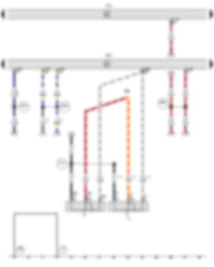
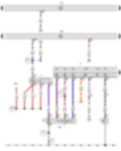
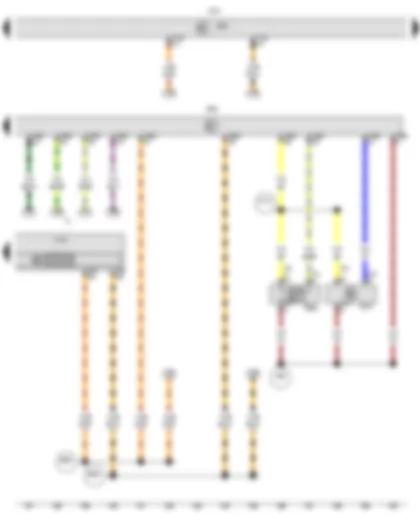
Wiring Diagram VW UP 2014 - Main relay - Onboard supply control unit - Engine control unit - Terminal 75 voltage supply relay 1 - Fuse holder C


Wiring Diagram  VW UP 2014 - Main relay - Onboard supply control unit - Engine control unit - Terminal 75 voltage supply relay 1 - Fuse holder C https://portal-diagnostov.com/license.html
https://portal-diagnostov.com/license.html Automotive Electricians Portal FZCO Automotive Electricians Portal FZCO
Download PDF file
J271 Main relay
J519 Onboard supply control unit
J623 Engine control unit
J680 Terminal 75 voltage supply relay 1
SC Fuse holder C
SC1 Fuse 1 on fuse holder C
SC3 Fuse 3 on fuse holder C
SC5 Fuse 5 on fuse holder C
SC19 Fuse 19 on fuse holder C
SC26 Fuse 26 on fuse holder C
SC31 Fuse 31 on fuse holder C
SC40 Fuse 40 on fuse holder C
SC42 Fuse 42 on fuse holder C
T7a 7-pin connector
T9 9-pin connector
T56a 56-pin connector
  A2 Positive connection (15), in dash panel wiring harness
  B146 Positive connection 1 (87), in interior wiring harness
  B315 Positive connection 1 (30a) in main wiring harness
  B321 Positive connection 7 (30a) in main wiring harness
  B325 Positive connection 11 (30a) in main wiring harness
*From November 2014
*2From November 2012
*3Up to November 2014
*4Up to November 2012
*5From May 2013
*6Up to November 2013
*7Up to May 2013
*8From November 2013

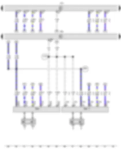
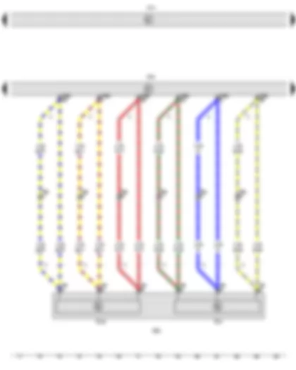
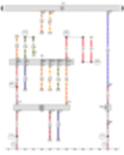
Wiring Diagram VW UP 2014 - Ignition/starter switch - Onboard supply control unit - Engine control unit


Wiring Diagram  VW UP 2014 - Ignition/starter switch - Onboard supply control unit - Engine control unit https://portal-diagnostov.com/license.html
https://portal-diagnostov.com/license.html Automotive Electricians Portal FZCO Automotive Electricians Portal FZCO
获取访问所有汽车的接线图Download PDF file
D Ignition/starter switch
J519 Onboard supply control unit
J623 Engine control unit
SB6 Fuse 6 on fuse holder B
T6a 6-pin connector
T7 7-pin connector
T56a 56-pin connector
T73b 73-pin connector
  A104 Positive connection 2 (15), in dash panel wiring harness
  B279 Positive connection 3 (15a) in main wiring harness
  B350 Positive connection 1 (87a) in main wiring harness
  B660 Connection (diagnosis terminal 50), in main wiring harness
*Up to November 2013
*2From November 2013
*3From November 2012
*4Up to November 2012

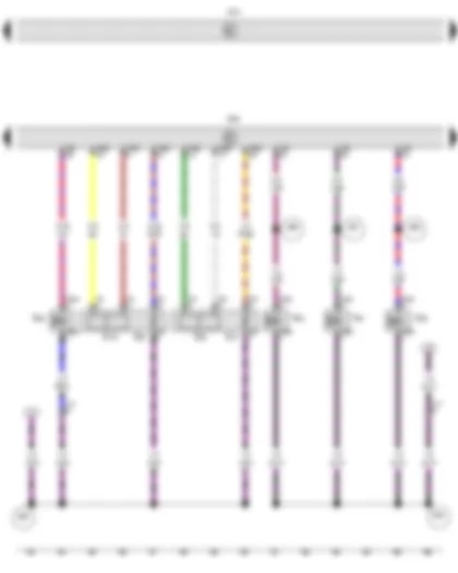
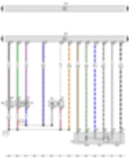
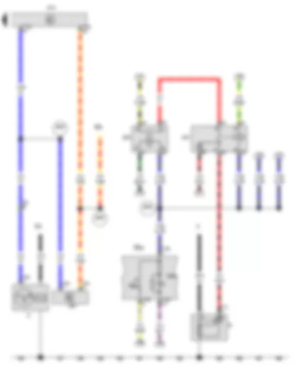
Wiring Diagram VW UP 2014 - Steering column combination switch - Onboard supply control unit - Engine control unit


Wiring Diagram  VW UP 2014 - Steering column combination switch - Onboard supply control unit - Engine control unit https://portal-diagnostov.com/license.html
https://portal-diagnostov.com/license.html Automotive Electricians Portal FZCO Automotive Electricians Portal FZCO
获取访问所有汽车的接线图Download PDF file
E45 Cruise control system switch
E227 Cruise control system (CCS) SET button
E595 Steering column combination switch
J519 Onboard supply control unit
J623 Engine control unit
T16d 16-pin connector
T41 41-pin connector
T56a 56-pin connector
T73a 73-pin connector
T73b 73-pin connector
  A130 Connection (CCS), in dash panel wiring harness
  B280 Positive connection 4 (15a) in main wiring harness
*Up to November 2013
*2Only models with cruise control system (CCS)
*3From November 2013

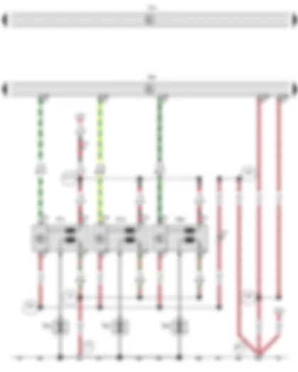
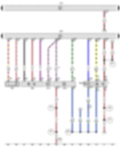
Wiring Diagram VW UP 2014 - Lambda probe - Lambda probe after catalytic converter - Onboard supply control unit - Engine control unit - Injector - cylinder 1 - Injector - cylinder 2 - Injector - cylinder 3


Wiring Diagram  VW UP 2014 - Lambda probe - Lambda probe after catalytic converter - Onboard supply control unit - Engine control unit - Injector - cylinder 1 - Injector - cylinder 2 - Injector - cylinder 3 https://portal-diagnostov.com/license.html
https://portal-diagnostov.com/license.html Automotive Electricians Portal FZCO Automotive Electricians Portal FZCO
获取访问所有汽车的接线图Download PDF file
G39 Lambda probe
G130 Lambda probe after catalytic converter
J519 Onboard supply control unit
J623 Engine control unit
N30 Injector, cylinder 1
N31 Injector, cylinder 2
N32 Injector, cylinder 3
N80 Activated charcoal filter solenoid valve 1
T2ba 2-pin connector
T2bb 2-pin connector
T2bc 2-pin connector
T2bd 2-pin connector
T4h 4-pin connector
T4i 4-pin connector
T14 14-pin connector
T56 56-pin connector
T56a 56-pin connector
Z19 Lambda probe heater
Z29 Lambda probe 1 heater after catalytic converter
  D95 Connection (injectors), in engine compartment wiring harness
  E29 Connection, in engine wiring harness
  E56 Connection 1, in injection system wiring harness
  E57 Connection 2, in injection system wiring harness
  E58 Connection 3, in injection system wiring harness

Wiring Diagram VW UP 2014 - Onboard supply control unit - Engine control unit - Ignition coil 1 with output stage - Ignition coil 2 with output stage - Ignition coil 3 with output stage


Wiring Diagram  VW UP 2014 - Onboard supply control unit - Engine control unit - Ignition coil 1 with output stage - Ignition coil 2 with output stage - Ignition coil 3 with output stage https://portal-diagnostov.com/license.html
https://portal-diagnostov.com/license.html Automotive Electricians Portal FZCO Automotive Electricians Portal FZCO
获取访问所有汽车的接线图Download PDF file
J519 Onboard supply control unit
J623 Engine control unit
N70 Ignition coil 1 with output stage
N127 Ignition coil 2 with output stage
N291 Ignition coil 3 with output stage
Q23 Spark plug 1
Q24 Spark plug 2
Q25 Spark plug 3
T4k 4-pin connector
T4m 4-pin connector
T4n 4-pin connector
T14 14-pin connector
T56 56-pin connector
T56a 56-pin connector
  85 Earth connection 1, in engine compartment wiring harness
  306 Earth connection (ignition coils), in engine prewiring harness
  394 Earth connection 29, in main wiring harness
  395 Earth connection 30, in main wiring harness
  D101 Connection 1 in engine compartment wiring harness

Wiring Diagram VW UP 2014 - Accelerator pedal module - Onboard supply control unit - Engine control unit


Wiring Diagram  VW UP 2014 - Accelerator pedal module - Onboard supply control unit - Engine control unit https://portal-diagnostov.com/license.html
https://portal-diagnostov.com/license.html Automotive Electricians Portal FZCO Automotive Electricians Portal FZCO
获取访问所有汽车的接线图Download PDF file
GX2 Accelerator pedal module
G79 Accelerator position sender
G185 Accelerator position sender 2
J519 Onboard supply control unit
J623 Engine control unit
T6f 6-pin connector
T6p 6-pin connector, on lower section of right A-pillar
T56a 56-pin connector
*Only left-hand drive models
*2Only right-hand drive models

Wiring Diagram VW UP 2014 - Hall sender - Intake air temperature sender - Coolant temperature sender - Intake manifold pressure sender - Throttle valve module - Onboard supply control unit - Engine control unit


Wiring Diagram  VW UP 2014 - Hall sender - Intake air temperature sender - Coolant temperature sender - Intake manifold pressure sender - Throttle valve module - Onboard supply control unit - Engine control unit https://portal-diagnostov.com/license.html
https://portal-diagnostov.com/license.html Automotive Electricians Portal FZCO Automotive Electricians Portal FZCO
获取访问所有汽车的接线图Download PDF file
G40 Hall sender
G42 Intake air temperature sender
G62 Coolant temperature sender
G71 Intake manifold pressure sender
G186 Throttle valve drive for electric throttle
G187 Throttle valve drive angle sender 1 for electric throttle
G188 Throttle valve drive angle sender 2 for electric throttle
J338 Throttle valve module
J519 Onboard supply control unit
J623 Engine control unit
T2be 2-pin connector
T3q 3-pin connector
T4o 4-pin connector
T6h 6-pin connector
T56 56-pin connector
  D102 Connection 2 in engine compartment wiring harness
  D103 Connection 3 in engine compartment wiring harness

Wiring Diagram VW UP 2014 - Brake light switch - Engine speed sender - Knock sensor 1 - Clutch position sender - Onboard supply control unit - Engine control unit - Camshaft control valve 1


Wiring Diagram  VW UP 2014 - Brake light switch - Engine speed sender - Knock sensor 1 - Clutch position sender - Onboard supply control unit - Engine control unit - Camshaft control valve 1 https://portal-diagnostov.com/license.html
https://portal-diagnostov.com/license.html Automotive Electricians Portal FZCO Automotive Electricians Portal FZCO
获取访问所有汽车的接线图Download PDF file
F Brake light switch
G28 Engine speed sender
G61 Knock sensor 1
G476 Clutch position sender
J514 Automated manual gearbox control unit
J519 Onboard supply control unit
J623 Engine control unit
N205 Camshaft control valve 1
T2bf 2-pin connector
T2bg 2-pin connector
T3s 3-pin connector
T4r 4-pin connector
T5g 5-pin connector
T14 14-pin connector
T30 30-pin connector
T56 56-pin connector
T56a 56-pin connector
T73a 73-pin connector
  376 Earth connection 11, in main wiring harness
  383 Earth connection 18, in main wiring harness
  387 Earth connection 22, in main wiring harness
  389 Earth connection 24, in main wiring harness
  B131 Connection (54), in interior wiring harness
  B351 Positive connection 2 (87a) in main wiring harness
*From November 2014
*2Only models with automatic gearbox
*3Only models with manual gearbox

Wiring Diagram VW UP 2014 - Oil pressure switch - Fuel delivery unit - Fuel pump relay - Onboard supply control unit - Engine control unit - Dash panel insert


Wiring Diagram  VW UP 2014 - Oil pressure switch - Fuel delivery unit - Fuel pump relay - Onboard supply control unit - Engine control unit - Dash panel insert https://portal-diagnostov.com/license.html
https://portal-diagnostov.com/license.html Automotive Electricians Portal FZCO Automotive Electricians Portal FZCO
获取访问所有汽车的接线图Download PDF file
F1 Oil pressure switch
G Fuel gauge sender
GX1 Fuel delivery unit
G6 Fuel system pressurisation pump
J17 Fuel pump relay
J285 Control unit in dash panel insert
J519 Onboard supply control unit
J623 Engine control unit
K Dash panel insert
K3 Oil pressure warning lamp
K31 Cruise control system warning lamp
K43 Coolant temperature warning lamp (too cold)
K54 Battery charge condition warning lamp: red LED for less than 12 Volt
K149 Engine electronics warning lamp
SC44 Fuse 44 on fuse holder C
T1c Single connector
T5a 5-pin connector
T10c 10-pin connector
T14 14-pin connector
T32 32-pin connector
T56 56-pin connector
T56a 56-pin connector
T73a 73-pin connector
  382 Earth connection 17, in main wiring harness
  410 Earth connection 1 (sender earth) in main wiring harness
  B332 Positive connection 18 (30a) in main wiring harness
  B701 Connection (fuel system diagnostic pump), in interior wiring harness
*From May 2014
*2Up to May 2014

Wiring Diagram VW UP 2014 - Brake servo pressure sensor - Gearbox neutral position sender - Onboard supply control unit - Data bus diagnostic interface - Engine control unit - Dash panel insert


Wiring Diagram  VW UP 2014 - Brake servo pressure sensor - Gearbox neutral position sender - Onboard supply control unit - Data bus diagnostic interface - Engine control unit - Dash panel insert https://portal-diagnostov.com/license.html
https://portal-diagnostov.com/license.html Automotive Electricians Portal FZCO Automotive Electricians Portal FZCO
获取访问所有汽车的接线图Download PDF file
G294 Brake servo pressure sensor
G701 Gearbox neutral position sender
J119 Multifunction indicator
J519 Onboard supply control unit
J533 Data bus diagnostic interface
J623 Engine control unit
K Dash panel insert
T3w 3-pin connector
T4t 4-pin connector
T32 32-pin connector
T56a 56-pin connector
T73b 73-pin connector
  396 Earth connection 31, in main wiring harness
  B383 Connection 1 (powertrain CAN bus, high), in main wiring harness
  B390 Connection 1 (powertrain CAN bus, low), in main wiring harness
  D107 Connection 5 in engine compartment wiring harness

Wiring Diagram VW UP 2014 - Voltage converter - Bonnet contact switch - Onboard supply control unit


Wiring Diagram  VW UP 2014 - Voltage converter - Bonnet contact switch - Onboard supply control unit https://portal-diagnostov.com/license.html
https://portal-diagnostov.com/license.html Automotive Electricians Portal FZCO Automotive Electricians Portal FZCO
获取访问所有汽车的接线图Download PDF file
A19 Voltage converter, under driver seat
F266 Bonnet contact switch
J329 Terminal 15 voltage supply relay
J519 Onboard supply control unit
SD Fuse holder D
SD2 Fuse 2 on fuse holder D
SA3 Fuse 3 in fuse holder A
SD4 Fuse 4 on fuse holder D
SD9 Fuse 9 on fuse holder D
SD10 Fuse 10 on fuse holder D
SD11 Fuse 11 on fuse holder D
SD12 Fuse 12 on fuse holder D
T2bs 2-pin connector
T7b 7-pin connector
T12a 12-pin connector
T73a 73-pin connector
T73b 73-pin connector
  375 Earth connection 10, in main wiring harness
  379 Earth connection 14, in main wiring harness
  A145 Positive connection 4 (15), in dash panel wiring harness
  B324 Positive connection 10 (30a) in main wiring harness
  B326 Positive connection 12 (30a) in main wiring harness
  B557 Positive connection 21 (30a) in main wiring harness

Wiring Diagram VW UP 2014 - Starter - Alternator - Start/Stop operation button - Battery monitor control unit - Onboard supply control unit - Starter relay 1 - Starter relay 2 - Start/Stop operation warning lamp


Wiring Diagram  VW UP 2014 - Starter - Alternator - Start/Stop operation button - Battery monitor control unit - Onboard supply control unit - Starter relay 1 - Starter relay 2 - Start/Stop operation warning lamp https://portal-diagnostov.com/license.html
https://portal-diagnostov.com/license.html Automotive Electricians Portal FZCO Automotive Electricians Portal FZCO
获取访问所有汽车的接线图Download PDF file
A Battery
B Starter
C Alternator
EX22 Centre switch module in dash panel
E693 Start/Stop operation button
J367 Battery monitor control unit
J519 Onboard supply control unit
J906 Starter relay 1
J907 Starter relay 2
K259 Start/Stop operation warning lamp
SA1 Fuse 1 in fuse holder A
SB5 Fuse 5 on fuse holder B
T1a Single connector
T2bf 2-pin connector
T2br 2-pin connector
T4f 4-pin connector
T16b 16-pin connector
T73b 73-pin connector
  B286 Positive connection 10 (15a) in main wiring harness
  B528 Connection 1 (LIN bus) in main wiring harness
  B558 Positive connection 22 (30a) in main wiring harness


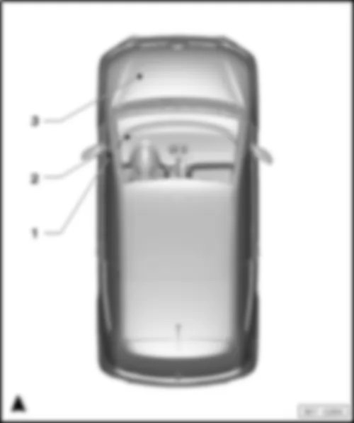
VW UP 2014 Overview of relay carriers

Overview of relay carriers
  Note:
Figure shows left-hand drive model
   
VW UP 2014 Overview of relay carriers https://portal-diagnostov.com/license.html
https://portal-diagnostov.com/license.html Automotive Electricians Portal FZCO Automotive Electricians Portal FZCO
获取访问所有汽车的接线图Download PDF file
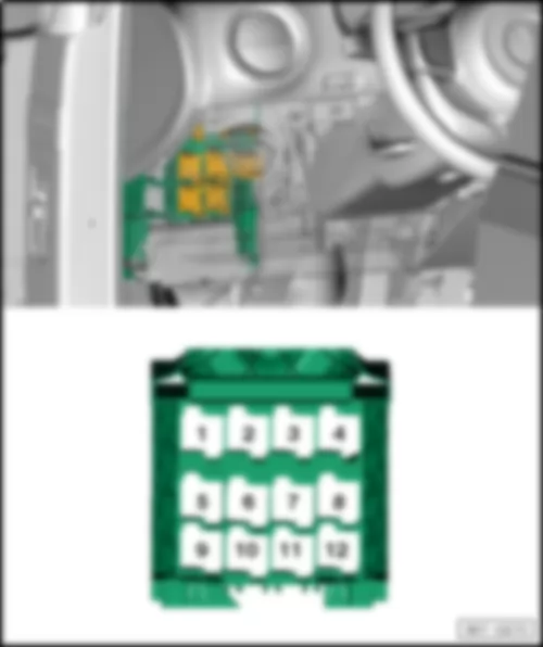
2 -  Relay​ and​ fuse​ holder​ 1 -SR1-
q   Location: and relay assignment from August 2011
q   Location and relay assignment for models with right-hand drive, from August 2011:


VW UP 2014

Relay assignment on relay and fuse carrier 1 -SR1- , from August 2011
  Note:
Figure shows left-hand drive model
   
VW UP 2014 https://portal-diagnostov.com/license.html
https://portal-diagnostov.com/license.html Automotive Electricians Portal FZCO Automotive Electricians Portal FZCO
获取访问所有汽车的接线图Download PDF file
1 -  Terminal​ 75​ voltage​ supply​ relay​ 1 -J680-
2 -  Terminal 15 voltage supply relay -J329-
3 -  Starter relay 2 -J907-
q   Models with start/stop system only
4 -  Main relay -J271-
5 -  Vacant
6 -  Starter relay 1 -J906-
q   Models with start/stop system only
7 -  Fuel pump relay -J17-
q   Slot 7/A
q   Models with a petrol engine only
7 -  Main and dip beam relay -J33-
q   Slot 7/B
q   Models with no start/stop system only
7 -  Emergency braking function relay -J1020-
q   Slot 7/B
q   Models with start/stop system only
8 -  Vacant
9 -  Vacant
10 -  Air conditioning system relay -J32-
11 -  Starter inhibitor relay -J207-
q   Slot 11/A
11 -  Relay for gas shut-off valves -J908-
q   Slot 11/B
q   Only models with CNG engine
12 -  Vacant

  Note:
Figure​ shows​ right-hand drive​ model
   
VW UP 2014 https://portal-diagnostov.com/license.html
https://portal-diagnostov.com/license.html Automotive Electricians Portal FZCO Automotive Electricians Portal FZCO
获取访问所有汽车的接线图Download PDF file
1 -  Terminal​ 75​ voltage​ supply​ relay​ 1 -J680-
2 -  Terminal 15 voltage supply relay -J329-
3 -  Starter relay 2 -J907-
q   Models with start/stop system only
4 -  Main relay -J271-
5 -  Vacant
6 -  Starter relay 1 -J906-
q   Models with start/stop system only
7 -  Fuel pump relay -J17-
q   Slot 7/A
q   Models with a petrol engine only
7 -  Main and dip beam relay -J33-
q   Slot 7/B
q   Models with no start/stop system only
7 -  Emergency braking function relay -J1020-
q   Slot 7/B
q   Models with start/stop system only
8 -  Vacant
9 -  Vacant
10 -  Air conditioning system relay -J32-
11 -  Starter inhibitor relay -J207-
q   Slot 11/A
11 -  Fuel pump relay -J17-
q   Slot 11/B
q   Only models with CNG engine
12 -  Vacant


VW UP 2014


VW UP 2014 Overview of control units

Overview of control units
VW UP 2014 Overview of control units https://portal-diagnostov.com/license.html
https://portal-diagnostov.com/license.html Automotive Electricians Portal FZCO Automotive Electricians Portal FZCO
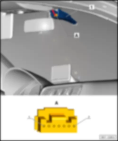
获取访问所有汽车的接线图Download PDF file
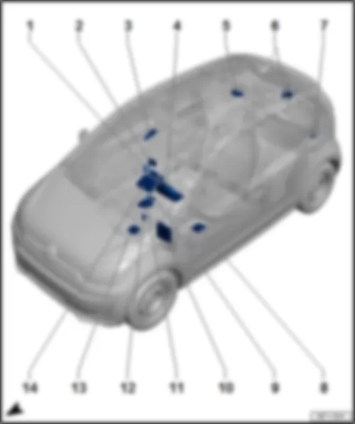
1 -  Heater control unit -J162-
q   Fitting location
1 -  Air​ conditioning​ system​ control​ unit​ -J301-
q   Fitting location
2 -  PID (portable navigation and infotainment system) -J982-
q   Fitting location
3 -  Emergency braking function sensor unit -J939-
q   Fitting location
4 -  Control unit in dash panel insert -J285-
q   Fitting location
5 -  Sliding sunroof control unit -J245-
q   Fitting location
6 -  Rear window wiper motor -V12-
q   Fitting location
7 -  Parking aid control unit -J446-
q   Fitting location
8 -  DC/DC voltage converter -A19-
q   Fitting location
9 -  Amplifier -R12-
q   Fitting location
10 -  Onboard supply control unit -J519-
q   Fitting location left-hand drive
q   Fitting location, right-hand drive
11 -  Power steering control unit -J500-
q   Fitting location left-hand drive
q   Fitting location, right-hand drive
12 -  Heated front seats control unit -J774-
q   Fitting location left-hand drive
q   Fitting location, right-hand drive
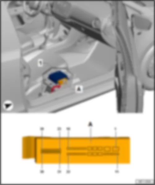
13 -  Airbag control unit -J234-
q   Fitting location
14 -  Radio -R-


VW UP 2014 Airbag control unit -J234-

Airbag control unit -J234-
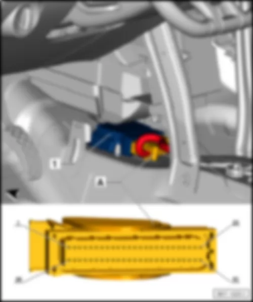
Fitting location of airbag control unit -J234-
   
VW UP 2014 Airbag control unit -J234- https://portal-diagnostov.com/license.html
https://portal-diagnostov.com/license.html Automotive Electricians Portal FZCO Automotive Electricians Portal FZCO
获取访问所有汽车的接线图Download PDF file
1 -  Airbag control unit -J234-
q   -A- 50-pin connector, -T50-

Back to overview


VW UP 2014 PID (portable navigation and infotainment system) -J982-

PID (portable navigation and infotainment system) -J982-
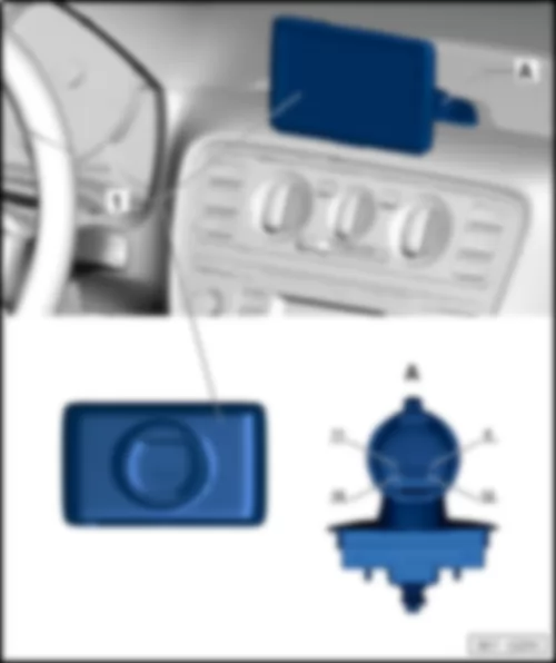
Fitting location of portable navigation and infotainment system -J982-
   
VW UP 2014 PID (portable navigation and infotainment system) -J982- https://portal-diagnostov.com/license.html
https://portal-diagnostov.com/license.html Automotive Electricians Portal FZCO Automotive Electricians Portal FZCO
获取访问所有汽车的接线图Download PDF file
1 -  PID (portable navigation and infotainment system) -J982-
q   -A- 16-pin connector -T16e-

Back to overview


VW UP 2014 Emergency braking function sensor unit -J939-

Emergency braking function sensor unit -J939-
Fitting location of emergency braking function sensor unit -J939-
   
VW UP 2014 Emergency braking function sensor unit -J939- https://portal-diagnostov.com/license.html
https://portal-diagnostov.com/license.html Automotive Electricians Portal FZCO Automotive Electricians Portal FZCO
获取访问所有汽车的接线图Download PDF file
1 -  Emergency braking function sensor unit -J939-
q   -A- 7-pin connector -T7c-

Connector assignment of emergency braking function sensor unit -J939-
   
-T7c- Designation
1 --
2 --
3 Powertrain CAN low
4 Powertrain CAN, high
5 Terminal 15
6 --
7 Terminal 31

Back to overview


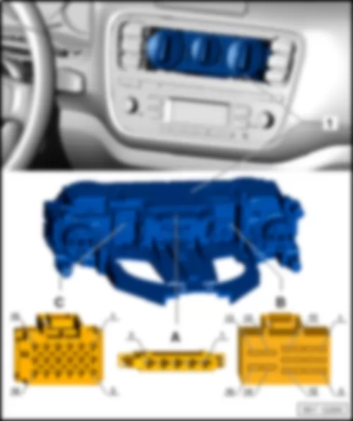
VW UP 2014 Heater control unit -J162-

Heater control unit -J162-
Fitting location of heater control unit -J162-
   
VW UP 2014 Heater control unit -J162- https://portal-diagnostov.com/license.html
https://portal-diagnostov.com/license.html Automotive Electricians Portal FZCO Automotive Electricians Portal FZCO
获取访问所有汽车的接线图Download PDF file
1 -  Heater control unit -J162-
q   -A- 5-connector -T5b-
q   -B- 16-pin connector -T16g-
q   -C- 18-pin connector -T18-

Connector assignment of heater control unit -J162-
   
-T5b- Designation   -T16g- Designation -T18- Designation
1 4th blower speed   1 --   1 --
2 3rd blower speed   2 --   2 --
3 2nd blower speed   3 --   3 --
4 1st blower speed   4 --   4 --
5 Supply +12V   5 --   5 --
    6 --   6 --
    7 --   7 --
    8 --   8 --
    9 --   9 --
    10 Terminal 31 10 --
    11 --   11 --
    12 Terminal 58d 12 --
    13 --   13 --
    14 --   14 --
    15 --   15 --
    16 --   16 --
        17 --
        18 --

Back to overview


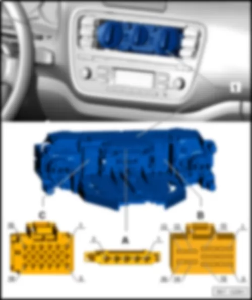
VW UP 2014 Air conditioning system control unit -J301-

Air conditioning system control unit -J301-
Fitting location of air conditioning system control unit -J301-
   
VW UP 2014 Air conditioning system control unit -J301- https://portal-diagnostov.com/license.html
https://portal-diagnostov.com/license.html Automotive Electricians Portal FZCO Automotive Electricians Portal FZCO
获取访问所有汽车的接线图Download PDF file
1 -  Air conditioning system control unit -J301-
q   -A- 5-connector -T5b-
q   -B- 16-pin connector -T16g-
q   -C- 18-pin connector -T18-

Connector assignment of air conditioning system control unit -J301-
   
-T5b- Designation   -T16g- Designation -T18- Designation
1 4th blower speed   1 AC signal   1 --
2 3rd blower speed   2 Evaporator earth   2 --
3 2nd blower speed   3 Evaporator signal   3 Evaporator temperature sensor signal
4 1st blower speed   4 --   4 Evaporator temperature sensor earth
5 Supply +12V   5 --   5 --
    6 --   6 --
    7 --   7 --
    8 --   8 --
    9 --   9 --
    10 Terminal 31 10 --
    11 Terminal 15 11 --
    12 Terminal 58d 12 --
    13 --   13 --
    14 --   14 --
    15 --   15 --
    16 --   16 --
        17 --
        18 --

Back to overview


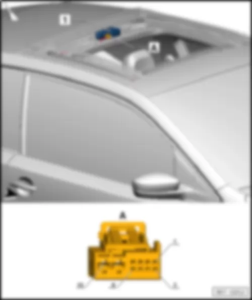
VW UP 2014 Sliding sunroof control unit -J245-

Sliding sunroof control unit -J245-
Fitting location of sliding sunroof adjustment control unit -J245-
   
VW UP 2014 Sliding sunroof control unit -J245- https://portal-diagnostov.com/license.html
https://portal-diagnostov.com/license.html Automotive Electricians Portal FZCO Automotive Electricians Portal FZCO
获取访问所有汽车的接线图Download PDF file
1 -  Sliding sunroof control unit -J245-
q   -A- 10-pin connector -T10a-

Connector assignment of sliding sunroof adjustment control unit -J245-
   
-T10a- Designation
1 LIN
2 Sliding sunroof adjustment regulator supply
3 Sliding sunroof adjustment regulator slider
4 Sliding sunroof adjustment regulator earth
5 --
6 --
7 Sunroof button, pull/push
8 --
9 Terminal 31
10 Terminal 30

Back to overview


VW UP 2014 Rear window wiper motor -V12-

Rear window wiper motor -V12-
Fitting location of rear window wiper motor -V12-
   
VW UP 2014 Rear window wiper motor -V12- https://portal-diagnostov.com/license.html
https://portal-diagnostov.com/license.html Automotive Electricians Portal FZCO Automotive Electricians Portal FZCO
获取访问所有汽车的接线图Download PDF file
1 -  Rear window wiper motor -V12-
q   -A- 4-pin connector -T4a-

Fitting location of rear window wiper motor -V12-
   
-T4a- Designation
1 Terminal 31
2 Steering column switch, intermittent
3 Steering column switch, rear wash
4 Terminal 75

Back to overview


VW UP 2014 Parking aid control unit -J446-

Parking aid control unit -J446-
Fitting location of parking aid control unit -J446-
   
VW UP 2014 Parking aid control unit -J446- https://portal-diagnostov.com/license.html
https://portal-diagnostov.com/license.html Automotive Electricians Portal FZCO Automotive Electricians Portal FZCO
获取访问所有汽车的接线图Download PDF file
1 -  Parking aid control unit -J446-
q   A = 16-pin connector -T16-
q   B - 12-pin connector -T12c-

Connector assignment of parking aid control unit -J446-
   
-T16- Designation   -T12c- Designation
1 Terminal 15   1 --
2 Rear sound sender signal   2 --
3 --   3 Rear, centre sensor signal
4 --   4 Rear, right sensor signal
5 --   5 Rear, left sensor signal
6 Powertrain CAN, high   6 --
7 --   7 --
8 Terminal 31   8 Rear sensor earth
9 --   9 --
10 Rear sound sender supply   10 --
11 --   11 Rear sensor current
12 --   12 --
13 --      
14 --      
15 Powertrain CAN low    
16 --      

Back to overview


VW UP 2014 Heated front seats control unit -J774-

Heated front seats control unit -J774-
Fitting location of heated front seats control unit -J774- for left-hand drive models
  Note
Figure shows left-hand drive model.
   
VW UP 2014 Heated front seats control unit -J774- https://portal-diagnostov.com/license.html
https://portal-diagnostov.com/license.html Automotive Electricians Portal FZCO Automotive Electricians Portal FZCO
获取访问所有汽车的接线图Download PDF file
1 -  Heated front seats control unit -J774-
q   -A- 16-pin connector -T16a-

Fitting location of heated front seats control unit -J774- for right-hand drive models
  Note
Figure shows right-hand drive model.
   
VW UP 2014 Heated front seats control unit -J774- https://portal-diagnostov.com/license.html
https://portal-diagnostov.com/license.html Automotive Electricians Portal FZCO Automotive Electricians Portal FZCO
获取访问所有汽车的接线图Download PDF file
1 -  Heated front seats control unit -J774-
q   -A- 16-pin connector -T16a-

Connector assignment of heated front seats control unit -J774-
   
-T16a- Designation     Designation
1 LED, stage 1, right   9 Terminal 31
2 LED, stage 2, left   10 --
3 LED, stage 2, right   11 --
4 LED, stage 1, left   12 Button for right seat heating
5 Seat heating authorisation, BCM   13 Terminal 75
6 Button for left seat heating   14 Terminal 75
7 -- 15 Seat heating left
8 -- 16 Seat heater right

Back to overview


VW UP 2014

DC/DC voltage converter1 -A19-
Fitting location of voltage converter -A19-
   
VW UP 2014 https://portal-diagnostov.com/license.html
https://portal-diagnostov.com/license.html Automotive Electricians Portal FZCO Automotive Electricians Portal FZCO
获取访问所有汽车的接线图Download PDF file
1 -  DC/DC voltage converter -A19-
q   -A- 12-pin connector -T12a-

1)  Only models with start/stop system
Pin assignment of voltage converter -A19-
   
-T12a- Designation
1 Terminal 30
2 Terminal 31
3 Terminal 15
4 Terminal 50
5 --
6 --
7 Terminal 30 stab
8 --
9 --
10 --
11 --
12 --

Back to overview


VW UP 2014 Control unit in dash panel insert -J285-

Control unit in dash panel insert -J285-
Fitting location of control unit in dash panel insert -J285-
   
VW UP 2014 Control unit in dash panel insert -J285- https://portal-diagnostov.com/license.html
https://portal-diagnostov.com/license.html Automotive Electricians Portal FZCO Automotive Electricians Portal FZCO
获取访问所有汽车的接线图Download PDF file
1 -  Control unit in dash panel insert -J285-
q   A- 32-pin connector -T32-

Connector assignment of control unit in dash panel insert -J285-
   
-T32- Designation     Designation
1 Tank sender 1 full   17 --
2 Tank sender 1 empty   18 Low coolant level
3 -- 19 Ambient temperature
4 -- 20 Terminal 31 sensor earth
5 -- 21 MFD to
6 -- 22 MFD from
7 Transponder 1   23 MFD OK/Reset
8 Transponder 2   24 Belt latch
9 Speedometer output   25 Parking brake/EPB
10 Speedometer input   26 Brakes, general
11 -- 27 Oil pressure
12 -- 28 Powertrain CAN, high
13 Rear fog light   29 Powertrain CAN low
14 Main beam   30 --
15 -- 31 Terminal 15
16 Terminal 31 32 Terminal 30

Back to overview


VW UP 2014 Power steering control unit -J500-

Power steering control unit -J500-
Fitting location of power steering control unit -J500- for left-hand drive models
  Note
Figure shows left-hand drive model.
   
VW UP 2014 Power steering control unit -J500- https://portal-diagnostov.com/license.html
https://portal-diagnostov.com/license.html Automotive Electricians Portal FZCO Automotive Electricians Portal FZCO
获取访问所有汽车的接线图Download PDF file
1 -  Power steering control unit -J500-
q   -A- 2-pin connector -T2aq-
q   -B- 3-pin connector -T3p-
q   -C- 6-pin connector -T6i-
q   -D- 6-pin connector -T6j-

Fitting location of power steering control unit -J500- for right-hand drive models
  Note
Figure shows right-hand drive model.
   
VW UP 2014 Power steering control unit -J500- https://portal-diagnostov.com/license.html
https://portal-diagnostov.com/license.html Automotive Electricians Portal FZCO Automotive Electricians Portal FZCO
获取访问所有汽车的接线图Download PDF file
1 -  Power steering control unit -J500-
q   -A- 2-pin connector -T2aq-
q   -B- 3-pin connector -T3p-
q   -C- 6-pin connector -T6i-
q   -D- 6-pin connector -T6j-

Connector assignment of power steering control unit -J500-
   
-T2aq- Designation   -T3p- Designation
1 Terminal 31 1 Powertrain CAN low
2 Terminal 30A 2 Powertrain CAN, high
    3 Terminal 15

Back to overview


VW UP 2014 Amplifier R12

Amplifier -R12-
Fitting location of amplifier -R12-
   
VW UP 2014 Amplifier R12 https://portal-diagnostov.com/license.html
https://portal-diagnostov.com/license.html Automotive Electricians Portal FZCO Automotive Electricians Portal FZCO
获取访问所有汽车的接线图Download PDF file
1 -  Amplifier -R12-
q   -A- 38-pin connector -T38a-

Connector assignment of amplifier -R12-
   
-T38a- Designation     Designation
1 Terminal 31   20 Front left treble loudspeaker -R20- , -
2 Terminal 30   21 Rear left loudspeaker -R4- , -
3 Front right loudspeaker -R3- , - 22 Rear right loudspeaker -R5- , +
4 -- 23 Convenience CAN bus high
5 -- 24 --
6 Front left loudspeaker -R2- , - 25 --
7 Front right treble loudspeaker -R22- , -   26 --
8 Front left treble loudspeaker -R20- , +   27 LR IN, -
9 Rear left loudspeaker -R4- , +   28 RR IN, -
10 Rear right loudspeaker -R5- , -   29 LF IN, -
11 Subwoofer -R211- , - 30 RF IN,-
12 Subwoofer -R211- , + 31 Convenience CAN bus low
13 Subwoofer -R211- , +   32 --
14 Subwoofer -R211- , -   33 --
15 Front right loudspeaker -R3- , + 34 --
16 -- 35 LR IN. +
17 --   36 RR IN, +
18 Front left loudspeaker -R2- , +   37 LF IN, +
19 Front right treble loudspeaker -R22- , +   38 RF IN, +

Back to overview


VW UP 2014 Onboard supply control unit -J519-

Onboard supply control unit -J519-
Fitting location of onboard supply control unit -J519- for left-hand drive models
  Note
Figure shows left-hand drive model.
   
VW UP 2014 Onboard supply control unit -J519- https://portal-diagnostov.com/license.html
https://portal-diagnostov.com/license.html Automotive Electricians Portal FZCO Automotive Electricians Portal FZCO
获取访问所有汽车的接线图Download PDF file
1 -  Onboard supply control unit -J519-
q   -A- 73-pin connector -T73a-, black
q   -B- 73-pin connector -T73b-, white

Fitting location of onboard supply control unit -J519- for right-hand drive models
  Note
Figure shows right-hand drive model.
   
VW UP 2014 Onboard supply control unit -J519- https://portal-diagnostov.com/license.html
https://portal-diagnostov.com/license.html Automotive Electricians Portal FZCO Automotive Electricians Portal FZCO
获取访问所有汽车的接线图Download PDF file
1 -  Onboard supply control unit -J519-
q   -A- 73-pin connector -T73a-, black
q   -B- 73-pin connector -T73b-, white

Connector assignment of onboard supply control unit -J519-
   
-T73a- Designation   -T73b- Designation
1 --   1 --
2 Left dipped beam   2 Right dipped beam
3 --   3 Left daytime running lights
4 Interior light dimmer   4 58D supply
5 Right daytime running lights   5 --
6 Rear fog light   6 --
7 Fog light, lighting rotary switch   7 Number plate light
8 --   8 --
9 Emergency braking function button   9 Left fog light with cornering light
10 Central locking authorisation motor, rear lid   10 Right fog light with cornering light
11 Central locking, lock motor, driver   11 Terminal 30 reversing lights, dipped beam
12 Central locking, common motor, driver   12 Reversing light
13 Central locking, safe, driver   13 Terminal 30 left turn signal/brake light
14 Terminal 31 central locking   14 Left turn signal
15 Central locking motor front passenger   15 Right turn signal
16 Terminal 30 central locking   16 Brake light
17 --   17 --
18 --   18 Powertrain CAN low
19 Driver door rotary latch   19 Powertrain CAN high
20 Passenger door rotary latch   20 Convenience CAN high
21 Central locking status lock, front passenger   21 Convenience CAN low
22 Central locking status lock, driver   22 CAN diagnosis low
23 Unlock rear lid   23 CAN diagnosis high
24 Central locking lock position, driver   24 LIN 2, roof
25 Central locking unlock button   25 --
26 --   26 --
27 Bonnet contact   27 Front wipers 1st stage, steering column lock switch
28 Hazard warning button   28 Central locking lock position, front passenger
29 Horn button   29 Rotary light switch - zero position
30 Rear lid main latch   30 --
31 Rear lid first latch   31 Heated rear window button
32 Right turn signal, steering column switch   32 Front wiper, end switch
33 Left turn signal, steering column switch   33 --
34 --   34 --
35 --   35 --
36 Seat heating authorisation   36 --
37 --   37 LIN, alternator
38 Heated exterior mirror   38 Terminal 31 electronics
39 Terminal 31 signal earth   39 Terminal 30 electronics
40 Right side light   40 Terminal 31 signal earth
41 Left side light   41 --
42 Terminal S ignition switch   42 --
43 Brake light sensor   43 Rear fog light, rotary light switch
44 Terminal 15 ignition switch   44 CCS set, steering column switch
45 Side light, rotary light switch   45 CCS E/A, steering column switch
46 --   46 CCS RES, steering column switch
47 --   47 CCS cancel, steering column switch
48 --   48 Reversing light switch
49 --   49 Terminal L
50 --   50 Terminal 50 ignition/starter switch
51 --   51 Terminal X ignition switch
52 Fuel pump relay   52 Dip beam position, rotary light switch
53 --   53 Front wipers 2nd stage, steering column lock switch
54 Terminal X relay   54 --
55 Starter inhibitor relay   55 Starter inhibitor signal
56 Hazard warning light button LED   56 Central locking status lock, rear lid
57 --   57 --
58 LED Safe LED   58 Heated exterior mirror switch
59 LED lock/unlock button   59 Terminal 30, reference
60 Heated rear window LED   60 Terminal 31 reference
61 --   61 Steering column switch, washer pump
62 Main beam, steering column switch   62 Steering column switch, front wiper intermittent
63 Terminal 30, left main/dipped beam, daytime driving lights 63 Heated rear window
64 Terminal 30 heated exterior mirror   64 --
65 Terminal 30G   65 --
66 Terminal 30, interior light/30G   66 --
67 --   67 Terminal 30 heated rear window
68 Terminal 30 windscreen wiper   68 Terminal 30, right main/dipped beam, daytime driving lights
69 Front wipers 1st stage   69 --
70 Brake earth, front wiper   70 --
71 Front wipers 2nd stage   71 --
72 Horn   72 --
73 Terminal 30 horn   73 --

Back to overview


VW UP 2014


VW UP 2014 Overview of control units in engine compartment, for models with left-hand drive

Overview of control units in engine compartment, for models with left-hand drive
  Note:
Figure shows left-hand drive model
   
VW UP 2014 Overview of control units in engine compartment, for models with left-hand drive https://portal-diagnostov.com/license.html
https://portal-diagnostov.com/license.html Automotive Electricians Portal FZCO Automotive Electricians Portal FZCO
获取访问所有汽车的接线图Download PDF file
1 -  Electronic manual gearbox control unit -J514-
q   Fitting location
2 -  Radiator fan control unit -J293-
q   Fitting location -T4g-, -T6g-
q   Fitting location -T10g-
3 -  Engine control unit -J623-
q   Fitting location
4 -  Wiper motor control unit -J400-
q   Fitting location -T4j-
5 -  ABS control unit -J104-
q   Fitting location


VW UP 2014 Overview of control units in engine compartment, for models with right-hand drive

Overview of control units in engine compartment, for models with right-hand drive
  Note:
Figure​ shows​ right-hand drive​ model
   
VW UP 2014 Overview of control units in engine compartment, for models with right-hand drive https://portal-diagnostov.com/license.html
https://portal-diagnostov.com/license.html Automotive Electricians Portal FZCO Automotive Electricians Portal FZCO
获取访问所有汽车的接线图Download PDF file
1 -  Electronic manual gearbox control unit -J514-
q   Fitting location
2 -  Radiator fan control unit -J293-
q   Fitting location -T4g-, -T6g-
q   Fitting location -T10g-
3 -  Engine control unit -J623-
q   Fitting location
4 -  Wiper motor control unit -J400-
q   Fitting location
5 -  ABS control unit -J104-
q   Fitting location

Electronic manual gearbox control unit -J514-
Fitting location electronic manual gearbox control unit -J514-
   
VW UP 2014 Overview of control units in engine compartment, for models with right-hand drive https://portal-diagnostov.com/license.html
https://portal-diagnostov.com/license.html Automotive Electricians Portal FZCO Automotive Electricians Portal FZCO
获取访问所有汽车的接线图Download PDF file
1 -  Electronic manual gearbox control unit -J514-
q   -A- 30-pin connector -T30-

Back to overview


VW UP 2014 Radiator fan control unit -J293-

Radiator fan control unit -J293-
Radiator fan control unit -J293- (T4x/2)
   
VW UP 2014 Radiator fan control unit -J293- https://portal-diagnostov.com/license.html
https://portal-diagnostov.com/license.html Automotive Electricians Portal FZCO Automotive Electricians Portal FZCO
获取访问所有汽车的接线图Download PDF file
1 -  Radiator fan control unit -J293-
q   -A- 4-pin connector -T4g-
q   -B- 6-pin connector -T6g-
  Note:
Depending on equipment

Connector assignment radiator fan control unit -J293-
   
-T4g- Designation   -T6g- Designation
1 Terminal 30a 1 Terminal 86a
2 Stage 1   2 Terminal 86b
3 Terminal 30b 3 Stage 1 Engine control unit
4 Stage 2   4 Stage 2 Engine control unit
      5 --
      6 --

Fitting location radiator fan control unit -J293- -T10g-
   
VW UP 2014 Radiator fan control unit -J293- https://portal-diagnostov.com/license.html
https://portal-diagnostov.com/license.html Automotive Electricians Portal FZCO Automotive Electricians Portal FZCO
获取访问所有汽车的接线图Download PDF file
1 -  Radiator fan control unit -J293-
q   -A- 10-pin connector -T10g-
  Note:
Depending on equipment

Connector assignment radiator fan control unit -J293-
   
-T10g- Designation
1 --
2 Terminal 86b
3 --
4 Stage 2 Engine control unit
5 Stage 1 Engine control unit
6 --
7 --
8 Stage 1
9 Terminal 30a
10 Stage 2

Back to overview


VW UP 2014 Engine control unit -J623-

Engine control unit -J623-
Fitting location of engine control unit -J623-
   
VW UP 2014 Engine control unit -J623- https://portal-diagnostov.com/license.html
https://portal-diagnostov.com/license.html Automotive Electricians Portal FZCO Automotive Electricians Portal FZCO
获取访问所有汽车的接线图Download PDF file
1 -  Engine control unit -J623-
q   -A- 56-pin connector -T56-
q   -B- 56-pin connector -T56a-

Back to overview


VW UP 2014 Wiper motor control unit -J400-

Wiper motor control unit -J400-
Fitting location of wiper motor control unit -J400- , only for models with left-hand drive
  Note:
Figure shows left-hand drive model
   
VW UP 2014 Wiper motor control unit -J400- https://portal-diagnostov.com/license.html
https://portal-diagnostov.com/license.html Automotive Electricians Portal FZCO Automotive Electricians Portal FZCO
获取访问所有汽车的接线图Download PDF file
1 -  Wiper motor control unit -J400-
q   -A- 4-pin connector -T4j-

Fitting location of wiper motor control unit -J400- , only for models with right-hand drive
  Note:
Figure​ shows​ right-hand drive​ model
   
VW UP 2014 Wiper motor control unit -J400- https://portal-diagnostov.com/license.html
https://portal-diagnostov.com/license.html Automotive Electricians Portal FZCO Automotive Electricians Portal FZCO
获取访问所有汽车的接线图Download PDF file
1 -  Wiper motor control unit -J400-
q   -A- 4-pin connector -T4j-

Connector assignment of wiper motor control unit -J400-
   
-T4j- Designation
1 Stage 2
2 Stage 1
3 Front wiper, end switch
4 Terminal 31

Back to overview


VW UP 2014 ABS control unit -J104-

ABS control unit -J104-
Fitting location of ABS control unit -J104-
   
VW UP 2014 ABS control unit -J104- https://portal-diagnostov.com/license.html
https://portal-diagnostov.com/license.html Automotive Electricians Portal FZCO Automotive Electricians Portal FZCO
获取访问所有汽车的接线图Download PDF file
1 -  ABS control unit -J104-
q   -A- 38-pin connector -T38-

Connector assignment of ABS control unit -J104-
   
-T38- Designation     Designation
1 Terminal 30_P   20 --
2 -- 21 --
3 Rear right speed sensor +   22 --
4 Rear right speed sensor -   23 --
5 -- 24 --
6 -- 25 Terminal 30_V
7 -- 26 --
8 Powertrain CAN, low   27 Terminal 30_L
9 Powertrain CAN, high   28 Terminal 15
10 Front right speed sensor +   29 Rear left speed sensor +
11 Front right speed sensor -   30 Rear right speed sensor -
12 -- 31 --
13 Earth_P 32 --
14 -- 33 --
15 -- 34 --
16 -- 35 Front left speed sensor +
17 -- 36 Front left speed sensor -
18 -- 37 --
19 -- 38 Earth_V

Back to overview


VW UP 2014 Overview of fuse holder

Overview of fuse holder
   
VW UP 2014 Overview of fuse holder https://portal-diagnostov.com/license.html
https://portal-diagnostov.com/license.html Automotive Electricians Portal FZCO Automotive Electricians Portal FZCO
获取访问所有汽车的接线图Download PDF file
q   Fuse assignment, from August 2011
q   Fuse assignment from May 2013
q   Fitting location right-hand drive
q   Fuse assignment, from August 2011
q   Fuse assignment from May 2013
q   Fuse assignment from November 2014
q   Fuse assignment, from August 2011
q   Fuse assignment from May 2013
q   Fuse assignment, from August 2011
q   Fuse assignment from May 2013


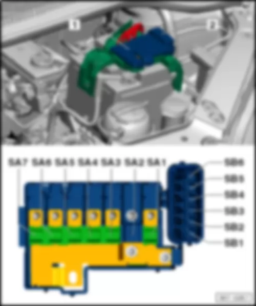
VW UP 2014 Fitting location fuse holder A SA

Fitting location fuse holder A -SA-
   
VW UP 2014 Fitting location fuse holder A SA https://portal-diagnostov.com/license.html
https://portal-diagnostov.com/license.html Automotive Electricians Portal FZCO Automotive Electricians Portal FZCO
获取访问所有汽车的接线图Download PDF file
1 -  Fuse holder A (SA)
⇒ Electrical system, Repair Group 97, Removing and installing fuse holders
Multifuse strip fuse
  Note
The strip fuse (Multifuse) must be replaced as a complete unit.
Back to overview


VW UP 2014

Fuse assignment fuse holder A -SA- , from August 2011
No. Current Flow Diagram designation Nominal value Function/component Terminal
SA1 B1 Fuse 1 on fuse holder A -SA1- 150 A
175 A 2
Alternator -C- 30
SA2 C1  
SA3 D1 Fuse 3 on fuse holder A -SA3- 110A Fuse holder C -SC- 30
Main relay -J271-  
        Terminal 75 voltage supply relay 1 -J680-  
SA4 E1 Fuse 4 on fuse holder A -SA4- 40A Power steering control unit -J500- 30
SA5 F1 Fuse 5 on fuse holder A -SA5- 40A ABS control unit -J104- 30
SA6 G1 Fuse 6 on fuse holder A -SA6- 40A Radiator fan control unit -J293- 30
SA7 H1 Fuse 7 on fuse holder A -SA7- 50A Automated manual gearbox control unit -J514-1 30

1 Depends on equipment
2 Only models with start/stop system
Back to overview


VW UP 2014

Fuse assignment fuse holder A -SA- , from May 2013
No. Current Flow Diagram designation Nominal value Function/component Terminal
SA1 B1 Fuse 1 on fuse holder A -SA1- 150 A
175 A 2
Alternator -C- 30
SA2 C1 Fuse 2 on fuse holder A -SA2- 30A Amplifier -R12- 30
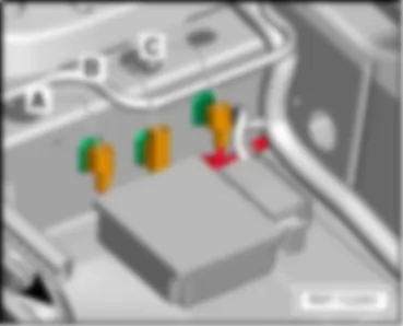
SA3 D1 Fuse 3 on fuse holder A -SA3- 110A Fuse holder C -SC- 30
Main relay -J271-  
        Terminal 75 voltage supply relay 1 -J680-  
SA4 E1 Fuse 4 on fuse holder A -SA4- 50A Power steering control unit -J500- 30
SA5 F1 Fuse 5 on fuse holder A -SA5- 40A ABS control unit -J104- 30
SA6 G1 Fuse 6 on fuse holder A -SA6- 40A Radiator fan control unit -J293- 30
SA7 H1 Fuse 7 on fuse holder A -SA7- 50A Automated manual gearbox control unit -J514-1 30

1 Depends on equipment
2 Only models with start/stop system
Back to overview


VW UP 2014 Fitting location fuse holder B SB

Fitting location fuse holder B -SB-
   
VW UP 2014 Fitting location fuse holder B SB https://portal-diagnostov.com/license.html
https://portal-diagnostov.com/license.html Automotive Electricians Portal FZCO Automotive Electricians Portal FZCO
获取访问所有汽车的接线图Download PDF file
2 -  Fuse holder B (SB)
 -  Fuse colours
50A - red
40A - orange
30A - light-green
25A - natural (white)
20A - yellow
15A - light blue
10A - red
7.5A - brown
5A - light-brown
3 A - violet
Back to overview


VW UP 2014

Fuse assignment fuse holder B -SB- , from August 2011
No. Current Flow Diagram designation Nominal value Function/component Terminal
SB1 J1 Fuse 1 on fuse holder B -SB1- 25A ABS control unit -J104- 30
SB2 J2 Fuse 2 on fuse holder B -SB2- 30A Radiator fan thermal switch -F18- 30
        Radiator fan control unit -J293-  
SB3 J3 Fuse 3 on fuse holder B -SB3- 5A Radiator fan control unit -J293- 30
        Terminal S ignition/starter switch -D-
SB4 J4 Fuse 4 on fuse holder B -SB4- 10A ABS control unit -J104- 30
SB5 J5 Fuse 5 on fuse holder B -SB5- 5A Onboard supply control unit -J519- 30
     
t  Reference
 
SB6 J6 Fuse 6 on fuse holder B -SB6- 30A Fuse holder C -SC-
Ignition/starter switch -D-
30

Back to overview


VW UP 2014

Fuse assignment fuse holder B -SB- , from May 2013
No. Current Flow Diagram designation Nominal value Function/component Terminal
SB1 J1 Fuse 1 on fuse holder B -SB1- 30A ABS control unit -J104- 30
SB2 J2 Fuse 2 on fuse holder B -SB2- 30A Radiator fan thermal switch -F18- 30
        Radiator fan control unit -J293-  
SB3 J3 Fuse 3 on fuse holder B -SB3- 7.5 A Radiator fan control unit -J293- 30
        Terminal S ignition/starter switch -D-
SB4 J4 Fuse 4 on fuse holder B -SB4- 10A ABS control unit -J104- 30
SB5 J5 Fuse 5 on fuse holder B -SB5- 7.5 A Onboard supply control unit -J519- 30
     
t  Reference
 
SB6 J6 Fuse 6 on fuse holder B -SB6- 30A Fuse holder C -SC-
Ignition/starter switch -D-
30

Back to overview


VW UP 2014 Fuse holder C SC

Fuse holder C -SC-
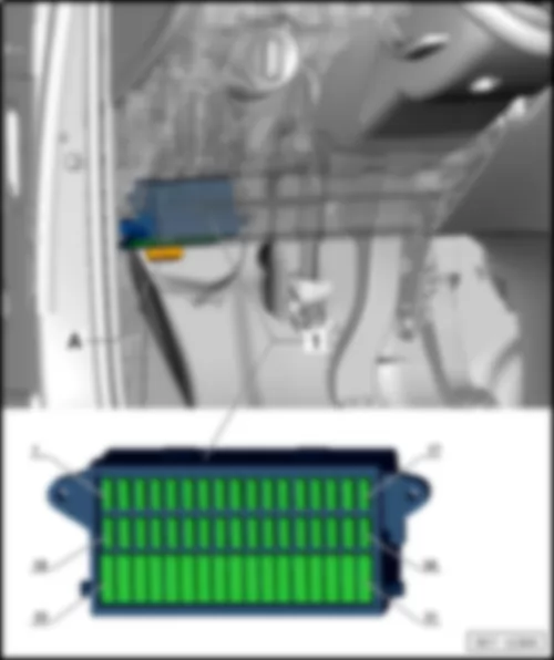
Fitting location fuse holder C -SC- , left-hand drive models
VW UP 2014 Fuse holder C SC https://portal-diagnostov.com/license.html
https://portal-diagnostov.com/license.html Automotive Electricians Portal FZCO Automotive Electricians Portal FZCO
获取访问所有汽车的接线图Download PDF file
1 -  Fuse holder C -SC-
 -  Fuse colours
50A - red
40A - orange
30A - light-green
25A - natural (white)
20A - yellow
15A - light blue
10A - red
7.5A - brown
5A - light-brown
3 A - violet

Back to overview
   
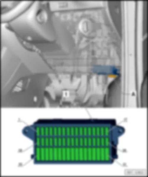
Fitting location fuse holder C -SC- , right-hand drive models
VW UP 2014 Fuse holder C SC https://portal-diagnostov.com/license.html
https://portal-diagnostov.com/license.html Automotive Electricians Portal FZCO Automotive Electricians Portal FZCO
获取访问所有汽车的接线图Download PDF file
 -  Fuse holder C -SC-
 -  Fuse colours
50A - red
40A - orange
30A - light-green
25A - natural (white)
20A - yellow
15A - light blue
10A - red
7.5A - brown
5A - light-brown
3 A - violet

Back to overview
   
Fuse assignment fuse holder C -SC- , from August 2011
No. Current Flow Diagram designation Nominal value Function/component Terminal
1 - Fuse 1 on fuse holder C -SC1- 5A Dash panel insert -K- 15
      Engine control unit -J623-  
      Radiator fan control unit -J293-
2 - Fuse 2 on fuse holder C -SC2- 15A Air conditioning system relay -J32- 15
      Air conditioning system control unit -J301-
      Diagnostic connection -U31-  
      High-pressure sender -G65-  
3 - Fuse 3 on fuse holder C -SC3- 7.5A Brake light switch -F- 87
      Clutch pedal switch -F36-  
      Camshaft control valve 1 -N205-  
4 - Fuse 4 on fuse holder C -SC4- 7.5A Onboard supply control unit -J519- 58
     
t  Light switch -E1- Dipped beam/daytime running lights/main beam
 
5 - Fuse 5 on fuse holder C -SC5- 5A Onboard supply control unit -J519-
t  Ignition/starter switch -D-
15
         
      CCS switch -E45-  
6 - Fuse 6 on fuse holder C -SC6- 5A Headlight range control regulator -E102- 15
      Left headlight range control motor -V48-  
      Right headlight range control motor -V49-  
      Mirror adjustment switch -E43-
7 - Fuse 7 on fuse holder C -SC7- 10A Selector lever -E313- 30
8 - Fuse 8 on fuse holder C -SC8- 7.5A Automated manual gearbox control unit -J514- 15
      Selector lever -E313-  
9 - Fuse 9 on fuse holder C -SC9- 7.5A Airbag control unit -J234- 15
      Centre switch module 2 in dash panel -EX35-
10 - Fuse 10 on fuse holder C -SC10- 5A Parking aid control unit -J446- 15
11 - Fuse 11 on fuse holder C -SC11- 10A Right headlight dipped beam bulb -M31- 56b
12 - Fuse 12 on fuse holder C -SC12- 5A Dash panel insert -K- 75
      Rear left fog light bulb -L46-  
13 - Fuse 13 on fuse holder C -SC13- 10A Left headlight dipped beam bulb -M29- 56b
14 - Fuse 14 on fuse holder C -SC14- 15A Rear window wiper motor -V12- 75
15 - Fuse 15 on fuse holder C -SC15- 15A Light switch -E1- 30
16 - Fuse 16 on fuse holder C -SC16- 5A Terminal 15 voltage supply relay -J329- 15
      Power steering control unit -J500-  
17 - Fuse 17 on fuse holder C -SC17- 15A Washer pump switch (automatic wash/wipe and headlight washer system) -E44- 15
18 - Fuse 18 on fuse holder C -SC18- 7.5A Reversing light switch -F4- 30
19 - Fuse 19 on fuse holder C -SC19- 15A Injector, cylinder 1 -N30- 87
      Injector, cylinder 2 -N31-
      Injector, cylinder 3 -N32-
20 - Fuse 20 on fuse holder C -SC20- 5A ABS control unit -J104- 15
      Emergency braking function sensor unit -J939-  
      Steering angle sender -G85-  
21 - Fuse 21 on fuse holder C -SC21- 5A Right side light bulb -M3- 58
      Right tail light bulb -M2-
      Number plate light -X-  
      Onboard supply control unit -J519-  
     
t  Light switch -E1- Side lights
 
22 - Fuse 22 on fuse holder C -SC22- 10A Left daytime running light bulb -L174- 58
      Right daytime running light bulb -L175-
23 - Fuse 23 on fuse holder C -SC23- 5A Left side light bulb -M1- 58
      Left tail light bulb -M4-  
24 - Fuse 24 on fuse holder C -SC24- 15A Headlight flasher switch -E5- 30
25 - Fuse 25 on fuse holder C -SC25- 10A Windscreen and rear window washer pump -V59- 53c
26 - Fuse 26 on fuse holder C -SC26- 5A Main relay -J271- 30
      Dash panel insert -K-  
      Steering angle sender -G85-  
27 - Fuse 27 on fuse holder C -SC27- 7.5A Onboard supply control unit -J519- 30
     
t  Front interior light -W1-
t  Front passenger reading light -W13-
t  Driver side reading light -W19-
 
28 - Fuse 28 on fuse holder C -SC28- 5A Diagnostic connection -U31- 30
29 - Fuse 29 on fuse holder C -SC29- 7.5A Onboard supply control unit -J519- 30
       
30 - Fuse 30 on fuse holder C -SC30- 5A Onboard supply control unit -J519- 30
     
t  Heated exterior mirror on driver side -Z4-
t  Heated exterior mirror on front passenger side -Z5-
 
31 - Fuse 31 on fuse holder C -SC31- 10A Lambda probe -G39- 87
      Lambda probe after catalytic converter -G130-
      Activated charcoal filter solenoid valve 1 -N80-  
32 - Fuse 32 on fuse holder C -SC32- 15A Onboard supply control unit -J519- 30
     
t  Turn signal/brake light
 
33 - Fuse 33 on fuse holder C -SC33- 10A Right headlight main beam bulb -M32- 56a
34 - Fuse 34 on fuse holder C -SC34- 10A Left headlight main beam bulb -M30- 56a
      Dash panel insert -K-  
35 - Fuse 35 on fuse holder C -SC35-      
36 - Fuse 36 on fuse holder C -SC36- 15A Cigarette lighter -U1- 75
37 - Fuse 37 on fuse holder C -SC37- 30A Air conditioning system control unit -J301- 75
      Heater control unit -J162-  
38 - Fuse 38 on fuse holder C -SC38- 15A Radio -R- 30
39 - Fuse 39 on fuse holder C -SC39- 30A Sliding sunroof adjustment control unit -J245- 30
40 - Fuse 40 on fuse holder C -SC40- 15A Engine control unit -J623- 87
41 - Fuse 41 on fuse holder C -SC41- 25A Onboard supply control unit -J519- 30
     
t  Central locking
 
42 - Fuse 42 on fuse holder C -SC42- 25A Ignition coil 1 with output stage -N70- 87
      Ignition coil 2 with output stage -N127-
      Ignition coil 3 with output stage -N291-
43 - Fuse 43 on fuse holder C -SC43- 20A Heated front seats control unit -J774- 75
      Switch module in centre of dash panel -EX22-
      Centre switch module 2 in dash panel -EX35-
44 - Fuse 44 on fuse holder C -SC44- 15A Fuel pump relay -J17- 30
45 - Fuse 45 on fuse holder C -SC45- 20A Light switch -E1- 15
46 - Fuse 46 on fuse holder C -SC46- 30A Onboard supply control unit -J519- 30
     
t  Heated rear window -Z1-
 
47 - Fuse 47 on fuse holder C -SC47- 25A Front right window regulator switch -E41- 15
48 - Fuse 48 on fuse holder C -SC48- 20A Onboard supply control unit -J519- 30
     
t  Treble horn -H2-
t  Bass horn -H7-
 
49 - Fuse 49 on fuse holder C -SC49- 20A Onboard supply control unit -J519- 30
     
t  Wiper motor control unit -J400-
 
50 - Fuse 50 on fuse holder C -SC50- 15A Left fog light bulb -L22- 55
      Right fog light bulb -L23-
51 - Fuse 51 on fuse holder C -SC51- 25A Front left window regulator switch -E40- 15

Back to overview
   
Fuse assignment fuse holder C -SC- , from May 2013
No. Current Flow Diagram designation Nominal value Function/component Terminal
1 - Fuse 1 on fuse holder C -SC1- 7.5A Dash panel insert -K- 15
      Engine control unit -J623-  
      Radiator fan control unit -J293-
2 - Fuse 2 on fuse holder C -SC2- 15A Air conditioning system relay -J32- 15
      Air conditioning system control unit -J301-
      Diagnostic connection -U31-  
      High-pressure sender -G65-  
3 - Fuse 3 on fuse holder C -SC3- 7.5A Brake light switch -F- 87
      Clutch pedal switch -F36-  
      Camshaft control valve 1 -N205-  
4 - Fuse 4 on fuse holder C -SC4- 7.5A Onboard supply control unit -J519- 58
     
t  Light switch -E1- Dipped beam/daytime running lights/main beam
 
5 - Fuse 5 on fuse holder C -SC5- 7.5A Onboard supply control unit -J519-
t  Ignition/starter switch -D-
15
         
      CCS switch -E45-  
6 - Fuse 6 on fuse holder C -SC6- 7.5A Headlight range control regulator -E102- 15
      Left headlight range control motor -V48-  
      Right headlight range control motor -V49-  
      Mirror adjustment switch -E43-
7 - Fuse 7 on fuse holder C -SC7- 10A Selector lever -E313- 30
8 - Fuse 8 on fuse holder C -SC8- 7.5A Automated manual gearbox control unit -J514- 15
      Selector lever -E313-  
9 - Fuse 9 on fuse holder C -SC9- 7.5A Airbag control unit -J234- 15
      Centre switch module 2 in dash panel -EX35-
10 - Fuse 10 on fuse holder C -SC10- 7.5A Parking aid control unit -J446- 15
11 - Fuse 11 on fuse holder C -SC11- 10A Right headlight dipped beam bulb -M31- 56b
12 - Fuse 12 on fuse holder C -SC12- 7.5A Dash panel insert -K- 55a
      Control unit in dash panel insert -J285-  
      Rear left fog light bulb -L46-  
      Onboard supply control unit -J519-  
13 - Fuse 13 on fuse holder C -SC13- 10A Left headlight dipped beam bulb -M29- 56b
14 - Fuse 14 on fuse holder C -SC14- 15A Rear window wiper motor -V12- 75
15 - Fuse 15 on fuse holder C -SC15- 15A Light switch -E1- 30
16 - Fuse 16 on fuse holder C -SC16- 7.5A Terminal 15 voltage supply relay -J329- 15
      Power steering control unit -J500-  
17 - Fuse 17 on fuse holder C -SC17- 15A Washer pump switch (automatic wash/wipe and headlight washer system) -E44- 15
18 - Fuse 18 on fuse holder C -SC18- 7.5A Reversing light switch -F4- 15
19 - Fuse 19 on fuse holder C -SC19- 15A Injector, cylinder 1 -N30- 87
    Injector, cylinder 2 -N31-
      Injector, cylinder 3 -N32-
20 - Fuse 20 on fuse holder C -SC20- 7.5A ABS control unit -J104- 15
    Emergency braking function sensor unit -J939-  
      Steering angle sender -G85-  
21 - Fuse 21 on fuse holder C -SC21- 7.5A Right side light bulb -M3- 58
      Right tail light bulb -M2-
      Number plate light -X-  
    Onboard supply control unit -J519-  
     
t  Light switch -E1- Side lights
 
22 - Fuse 22 on fuse holder C -SC22- 10A Left daytime running light bulb -L174- 58
      Right daytime running light bulb -L175-
23 - Fuse 23 on fuse holder C -SC23- 7.5A Left side light bulb -M1- 58
      Left tail light bulb -M4-  
24 - Fuse 24 on fuse holder C -SC24- 15A Headlight flasher switch -E5- 30
25 - Fuse 25 on fuse holder C -SC25- 10A Windscreen and rear window washer pump -V59- 53c
26 - Fuse 26 on fuse holder C -SC26- 7.5A Main relay -J271- 30
    Dash panel insert -K-  
      Steering angle sender -G85-  
27 - Fuse 27 on fuse holder C -SC27- 7.5A Onboard supply control unit -J519- 30
     
t  Front interior light -W1-
t  Front passenger reading light -W13-
t  Driver side reading light -W19-
 
28 - Fuse 28 on fuse holder C -SC28- 7.5A Diagnostic connection -U31- 30
29 - Fuse 29 on fuse holder C -SC29- 7.5A Onboard supply control unit -J519- 30
       
30 - Fuse 30 on fuse holder C -SC30- 7.5A Onboard supply control unit -J519- 30
     
t  Heated exterior mirror on driver side -Z4-
t  Heated exterior mirror on front passenger side -Z5-
 
31 - Fuse 31 on fuse holder C -SC31- 10A Lambda probe -G39- 87
    Lambda probe after catalytic converter -G130-
      Activated charcoal filter solenoid valve 1 -N80-  
32 - Fuse 32 on fuse holder C -SC32- 15A Onboard supply control unit -J519- 30
     
t  Turn signal/brake light
 
33 - Fuse 33 on fuse holder C -SC33- 10A Right headlight main beam bulb -M32- 56a
34 - Fuse 34 on fuse holder C -SC34- 10A Left headlight main beam bulb -M30- 56a
      Dash panel insert -K-  
35 - Fuse 35 on fuse holder C -SC35-      
36 - Fuse 36 on fuse holder C -SC36- 20A Cigarette lighter -U1- 75
37 - Fuse 37 on fuse holder C -SC37- 30A Air conditioning system control unit -J301- 75
      Heater control unit -J162-  
38 - Fuse 38 on fuse holder C -SC38- 15A Radio -R- 30
39 - Fuse 39 on fuse holder C -SC39- 30A Sliding sunroof adjustment control unit -J245- 30
40 - Fuse 40 on fuse holder C -SC40- 15A Engine control unit -J623- 87
41 - Fuse 41 on fuse holder C -SC41- 25A Onboard supply control unit -J519- 30
     
t  Central locking
 
42 - Fuse 42 on fuse holder C -SC42- 25A Ignition coil 1 with output stage -N70- 87
    Ignition coil 2 with output stage -N127-
      Ignition coil 3 with output stage -N291-
43 - Fuse 43 on fuse holder C -SC43- 20A Heated front seats control unit -J774- 75
    Switch module in centre of dash panel -EX22-
      Centre switch module 2 in dash panel -EX35-
44 - Fuse 44 on fuse holder C -SC44- 15A Fuel pump relay -J17- 30
45 - Fuse 45 on fuse holder C -SC45- 20A Light switch -E1- 15
46 - Fuse 46 on fuse holder C -SC46- 30A Onboard supply control unit -J519- 30
     
t  Heated rear window -Z1-
 
47 - Fuse 47 on fuse holder C -SC47- 30A Front right window regulator switch -E41- 15
48 - Fuse 48 on fuse holder C -SC48- 20A Onboard supply control unit -J519- 30
     
t  Treble horn -H2-
t  Bass horn -H7-
 
49 - Fuse 49 on fuse holder C -SC49- 30A Onboard supply control unit -J519- 30
     
t  Wiper motor control unit -J400-
 
50 - Fuse 50 on fuse holder C -SC50- 15A Left fog light bulb -L22- 55
      Right fog light bulb -L23-
      20A1 Onboard supply control unit -J519-1  
51 - Fuse 51 on fuse holder C -SC51- 30A Front left window regulator switch -E40- 15

1 Only models with start/stop system
Back to overview
   
Fuse assignment fuse holder C -SC- , from November 2014
No. Current Flow Diagram designation Nominal value Function/component Terminal
1 - Fuse 1 on fuse holder C -SC1- 7.5A Dash panel insert -K- 15
      Engine control unit -J623-  
      Radiator fan control unit -J293-
2 - Fuse 2 on fuse holder C -SC2- 15A Air conditioning system relay -J32- 15
      Air conditioning system control unit -J301-
      Diagnostic connection -U31-  
      High-pressure sender -G65-  
3 - Fuse 3 on fuse holder C -SC3- 7.5A Brake light switch -F- 87
      Clutch pedal switch -F36-  
      Camshaft control valve 1 -N205-  
4 - Fuse 4 on fuse holder C -SC4- 7.5A Onboard supply control unit -J519- 58
     
t  Light switch -E1- Dipped beam/daytime running lights/main beam
 
5 - Fuse 5 on fuse holder C -SC5- 7.5A Onboard supply control unit -J519-
t  Ignition/starter switch -D-
15
         
      CCS switch -E45-  
6 - Fuse 6 on fuse holder C -SC6- 7.5A Headlight range control regulator -E102- 15
      Left headlight range control motor -V48-  
      Right headlight range control motor -V49-  
      Mirror adjustment switch -E43-
7 - Fuse 7 on fuse holder C -SC7- 10A Selector lever -E313- 30
8 - Fuse 8 on fuse holder C -SC8- 7.5A Automated manual gearbox control unit -J514- 15
      Selector lever -E313-  
9 - Fuse 9 on fuse holder C -SC9- 7.5A Airbag control unit -J234- 15
      Centre switch module 2 in dash panel -EX35-
10 - Fuse 10 on fuse holder C -SC10- 7.5A Parking aid control unit -J446- 15
11 - Fuse 11 on fuse holder C -SC11- 10A Right headlight dipped beam bulb -M31- 56b
12 - Fuse 12 on fuse holder C -SC12- 7.5A Dash panel insert -K- 55a
      Control unit in dash panel insert -J285-  
      Rear left fog light bulb -L46-  
      Onboard supply control unit -J519-  
13 - Fuse 13 on fuse holder C -SC13- 10A Left headlight dipped beam bulb -M29- 56b
14 - Fuse 14 on fuse holder C -SC14- 15A Rear window wiper motor -V12- 75
15 - Fuse 15 on fuse holder C -SC15- 15A Light switch -E1- 30
16 - Fuse 16 on fuse holder C -SC16- 7.5A Terminal 15 voltage supply relay -J329- 15
      Power steering control unit -J500-  
17 - Fuse 17 on fuse holder C -SC17- 15A Washer pump switch (automatic wash/wipe and headlight washer system) -E44- 15
18 - Fuse 18 on fuse holder C -SC18- 7.5A Reversing light switch -F4- 15
19 - Fuse 19 on fuse holder C -SC19- 15A Injector, cylinder 1 -N30- 87
    Injector, cylinder 2 -N31-
      Injector, cylinder 3 -N32-
20 - Fuse 20 on fuse holder C -SC20- 7.5A ABS control unit -J104- 15
    Emergency braking function sensor unit -J939-  
      Steering angle sender -G85-  
21 - Fuse 21 on fuse holder C -SC21- 7.5A Right side light bulb -M3- 58
      Right tail light bulb -M2-
      Number plate light -X-  
    Onboard supply control unit -J519-  
     
t  Light switch -E1- Side lights
 
22 - Fuse 22 on fuse holder C -SC22- 10A Left daytime running light bulb -L174- 58
      Right daytime running light bulb -L175-
23 - Fuse 23 on fuse holder C -SC23- 7.5A Left side light bulb -M1- 58
      Left tail light bulb -M4-  
24 - Fuse 24 on fuse holder C -SC24- 15A Headlight flasher switch -E5- 30
25 - Fuse 25 on fuse holder C -SC25- 10A Windscreen and rear window washer pump -V59- 53c
26 - Fuse 26 on fuse holder C -SC26- 7.5A Main relay -J271- 30
    Dash panel insert -K-  
      Steering angle sender -G85-  
27 - Fuse 27 on fuse holder C -SC27- 7.5A Onboard supply control unit -J519- 30
     
t  Front interior light -W1-
t  Front passenger reading light -W13-
t  Driver side reading light -W19-
 
28 - Fuse 28 on fuse holder C -SC28- 7.5A Diagnostic connection -U31- 30
29 - Fuse 29 on fuse holder C -SC29- 7.5A Onboard supply control unit -J519- 30
       
30 - Fuse 30 on fuse holder C -SC30- 7.5A Onboard supply control unit -J519- 30
     
t  Heated exterior mirror on driver side -Z4-
t  Heated exterior mirror on front passenger side -Z5-
 
31 - Fuse 31 on fuse holder C -SC31- 10A Lambda probe -G39- 87
    Lambda probe after catalytic converter -G130-
      Activated charcoal filter solenoid valve 1 -N80-  
32 - Fuse 32 on fuse holder C -SC32- 15A Onboard supply control unit -J519- 30
     
t  Turn signal/brake light
 
33 - Fuse 33 on fuse holder C -SC33- 10A Right headlight main beam bulb -M32- 56a
34 - Fuse 34 on fuse holder C -SC34- 10A Left headlight main beam bulb -M30- 56a
      Dash panel insert -K-  
35 - Fuse 35 on fuse holder C -SC35-      
36 - Fuse 36 on fuse holder C -SC36- 20A Cigarette lighter -U1- 75
37 - Fuse 37 on fuse holder C -SC37- 30A Air conditioning system control unit -J301- 75
      Heater control unit -J162-  
38 - Fuse 38 on fuse holder C -SC38- 15A Radio -R- 30
39 - Fuse 39 on fuse holder C -SC39- 30A Sliding sunroof adjustment control unit -J245- 30
40 - Fuse 40 on fuse holder C -SC40- 15A Engine control unit -J623- 87
41 - Fuse 41 on fuse holder C -SC41- 25A Onboard supply control unit -J519- 30
     
t  Central locking
 
42 - Fuse 42 on fuse holder C -SC42- 25A Ignition coil 1 with output stage -N70- 87
    Ignition coil 2 with output stage -N127-
      Ignition coil 3 with output stage -N291-
43 - Fuse 43 on fuse holder C -SC43- 20A Heated front seats control unit -J774- 75
    Switch module in centre of dash panel -EX22-
      Centre switch module 2 in dash panel -EX35-
44 - Fuse 44 on fuse holder C -SC44- 15A Fuel pump relay -J17- 30
45 - Fuse 45 on fuse holder C -SC45- 20A Light switch -E1- 15
46 - Fuse 46 on fuse holder C -SC46- 30A Onboard supply control unit -J519- 30
     
t  Heated rear window -Z1-
 
47 - Fuse 47 on fuse holder C -SC47- 30A Front right window regulator switch -E41-
Operating unit for window regulator in driver door -E512-2
Driver side central locking lock unit -F220-
15
48 - Fuse 48 on fuse holder C -SC48- 20A Onboard supply control unit -J519- 30
     
t  Treble horn -H2-
t  Bass horn -H7-
 
49 - Fuse 49 on fuse holder C -SC49- 30A Onboard supply control unit -J519- 30
     
t  Wiper motor control unit -J400-
 
50 - Fuse 50 on fuse holder C -SC50- 15A Left fog light bulb -L22- 55
      Right fog light bulb -L23-
      20A1 Onboard supply control unit -J519-1  
51 - Fuse 51 on fuse holder C -SC51- 30A Operating unit for window regulator in driver door -E512-
Driver side central locking lock unit -F220-2
15

1 Only models with start/stop system
2 Only right-hand drive models
Back to overview
   
Fuse holder D -SD-
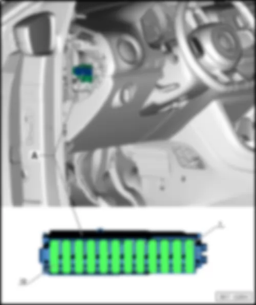
Fitting location fuse holder D -SD- , left-hand drive models
VW UP 2014 Fuse holder C SC https://portal-diagnostov.com/license.html
https://portal-diagnostov.com/license.html Automotive Electricians Portal FZCO Automotive Electricians Portal FZCO
获取访问所有汽车的接线图Download PDF file
A -  Fuse holder D -SD-
q   Only models with start/stop system
 -  Fuse colours
50A - red
40A - orange
30A - light-green
25A - natural (white)
20A - yellow
15A - light blue
10A - red
7.5A - brown
5A - light-brown
3 A - violet
Back to overview

   
Fuse assignment on fuse holder D -SD- , from August 2011
No. Current Flow Diagram designation Nominal value Function/component Terminal
SD1   Fuse 1 on fuse holder D -SD1- 5A Emergency braking function sensor unit -J939- 30
SD2   Fuse 2 on fuse holder D -SD2- 5A Dash panel insert -K- 30
SD3   Fuse 3 on fuse holder D -SD3- 10A Radio -R- 30
SD4   Fuse 4 on fuse holder D -SD4- 7.5 A Voltage converter -A19-
Starter relay 1 -J906-
Starter relay 2 -J907-
15
SD5      
SD6      
SD7      
SD8      
SD9   Fuse 9 on fuse holder D -SD9- 15A Onboard supply control unit -J519-
t  Right main beam/dipped beam/daytime driving lights
30
SD10   Fuse 10 on fuse holder D -SD10- 15A Onboard supply control unit -J519-
t  Left main beam/dipped beam/daytime driving lights
30
SD11   Fuse 11 on fuse holder D -SD11- 30A Starter relay 1 -J906-
Starter relay 2 -J907-
30
SD12   Fuse 12 on fuse holder D -SD12- 30A Voltage converter -A19- 30

Back to overview
   
Fuse assignment on fuse holder D -SD- , from May 2013
No. Current Flow Diagram designation Nominal value Function/component Terminal
SD1   Fuse 1 on fuse holder D -SD1- 7.5A Relay for emergency braking function -J1020-
Emergency braking function sensor unit -J939-
30
SD2   Fuse 2 on fuse holder D -SD2- 7.5A Dash panel insert -K- 30
SD3   Fuse 3 on fuse holder D -SD3- 15A Radio -R- 30
SD4   Fuse 4 on fuse holder D -SD4- 7.5 A Voltage converter -A19-
Starter relay 1 -J906-
Starter relay 2 -J907-
15
SD5      
SD6      
SD7      
SD8      
SD9   Fuse 9 on fuse holder D -SD9- 15A Onboard supply control unit -J519-
t  Right main beam/dipped beam/daytime driving lights
30
SD10   Fuse 10 on fuse holder D -SD10- 15A Onboard supply control unit -J519-
t  Left main beam/dipped beam/daytime driving lights
30
SD11   Fuse 11 on fuse holder D -SD11- 30A Starter relay 1 -J906-
Starter relay 2 -J907-
30
SD12   Fuse 12 on fuse holder D -SD12- 30A Voltage converter -A19- 30

Back to overview


VW UP 2014


VW UP 2014 Overview of earth points

Overview of earth points
   
VW UP 2014 Overview of earth points https://portal-diagnostov.com/license.html
https://portal-diagnostov.com/license.html Automotive Electricians Portal FZCO Automotive Electricians Portal FZCO
获取访问所有汽车的接线图Download PDF file
   18 Earth point on cylinder block
q   Fitting location
   685 Earth point 1 on front of right longitudinal member
q   Fitting location

   
VW UP 2014 Overview of earth points https://portal-diagnostov.com/license.html
https://portal-diagnostov.com/license.html Automotive Electricians Portal FZCO Automotive Electricians Portal FZCO
获取访问所有汽车的接线图Download PDF file

   
VW UP 2014 Overview of earth points https://portal-diagnostov.com/license.html
https://portal-diagnostov.com/license.html Automotive Electricians Portal FZCO Automotive Electricians Portal FZCO
获取访问所有汽车的接线图Download PDF file

   
VW UP 2014 Overview of earth points https://portal-diagnostov.com/license.html
https://portal-diagnostov.com/license.html Automotive Electricians Portal FZCO Automotive Electricians Portal FZCO
获取访问所有汽车的接线图Download PDF file


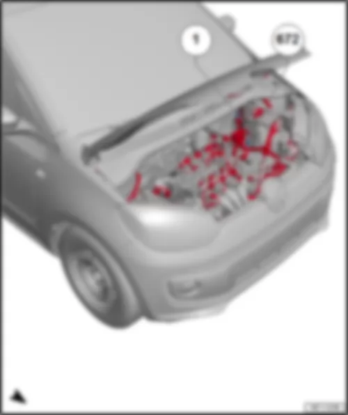
VW UP 2014 Earth points, in engine compartment

Earth points, in engine compartment
   
VW UP 2014 Earth points, in engine compartment https://portal-diagnostov.com/license.html
https://portal-diagnostov.com/license.html Automotive Electricians Portal FZCO Automotive Electricians Portal FZCO
获取访问所有汽车的接线图Download PDF file
   1 Earth strap, battery - body
q   Specified torque 20 Nm

Back to overview
   
VW UP 2014 Earth points, in engine compartment https://portal-diagnostov.com/license.html
https://portal-diagnostov.com/license.html Automotive Electricians Portal FZCO Automotive Electricians Portal FZCO
获取访问所有汽车的接线图Download PDF file
   13 Earth point on right in engine compartment
q   Specified torque 9 Nm

Back to overview
   
VW UP 2014 Earth points, in engine compartment https://portal-diagnostov.com/license.html
https://portal-diagnostov.com/license.html Automotive Electricians Portal FZCO Automotive Electricians Portal FZCO
获取访问所有汽车的接线图Download PDF file
   18 Earth point on cylinder block
q   Specified torque 20 Nm

Back to overview
   
VW UP 2014 Earth points, in engine compartment https://portal-diagnostov.com/license.html
https://portal-diagnostov.com/license.html Automotive Electricians Portal FZCO Automotive Electricians Portal FZCO
获取访问所有汽车的接线图Download PDF file
   671 Earth point 1 on front of left longitudinal member
q   Specified torque 9 Nm

Back to overview
   
VW UP 2014 Earth points, in engine compartment https://portal-diagnostov.com/license.html
https://portal-diagnostov.com/license.html Automotive Electricians Portal FZCO Automotive Electricians Portal FZCO
获取访问所有汽车的接线图Download PDF file
   672 Earth point 2 on front of left longitudinal member
q   Specified torque 9 Nm

Back to overview
   
VW UP 2014 Earth points, in engine compartment https://portal-diagnostov.com/license.html
https://portal-diagnostov.com/license.html Automotive Electricians Portal FZCO Automotive Electricians Portal FZCO
获取访问所有汽车的接线图Download PDF file
   764 Earth point in front left wheel housing
q   Specified torque 20 Nm

Back to overview


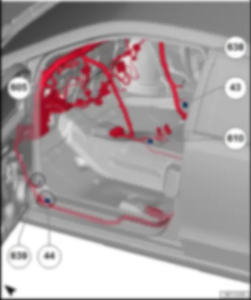
VW UP 2014 Overview of earth points in passenger compartment

Overview of earth points in passenger compartment
   
VW UP 2014 Overview of earth points in passenger compartment https://portal-diagnostov.com/license.html
https://portal-diagnostov.com/license.html Automotive Electricians Portal FZCO Automotive Electricians Portal FZCO
获取访问所有汽车的接线图Download PDF file
   43 Earth point, lower part of right A-pillar
q   Specified torque 9 Nm
   638 Earth point, on right A-pillar1
q   Specified torque 9 Nm

1)  Only right-hand drive models
Back to overview
   
VW UP 2014 Overview of earth points in passenger compartment https://portal-diagnostov.com/license.html
https://portal-diagnostov.com/license.html Automotive Electricians Portal FZCO Automotive Electricians Portal FZCO
获取访问所有汽车的接线图Download PDF file
   44 Earth point on lower part of left A-pillar
q   Specified torque 9 Nm
   639 Earth point, left A-pillar1
q   Specified torque 9 Nm

2)  Only for models with left-hand drive
Back to overview
   
VW UP 2014 Overview of earth points in passenger compartment https://portal-diagnostov.com/license.html
https://portal-diagnostov.com/license.html Automotive Electricians Portal FZCO Automotive Electricians Portal FZCO
获取访问所有汽车的接线图Download PDF file
   605 Earth point on top end of steering column
q   Specified torque 9 Nm

Back to overview
   
VW UP 2014 Overview of earth points in passenger compartment https://portal-diagnostov.com/license.html
https://portal-diagnostov.com/license.html Automotive Electricians Portal FZCO Automotive Electricians Portal FZCO
获取访问所有汽车的接线图Download PDF file
   610 Earth point (audio), front below centre console
q   Specified torque 9 Nm

Back to overview


VW UP 2014 Earth points in luggage compartment

Earth points in luggage compartment
   
VW UP 2014 Earth points in luggage compartment https://portal-diagnostov.com/license.html
https://portal-diagnostov.com/license.html Automotive Electricians Portal FZCO Automotive Electricians Portal FZCO
获取访问所有汽车的接线图Download PDF file
q   Specified torque 9 Nm

Back to overview


VW UP 2014 Overview of coupling stations and connectors

Overview of coupling stations and connectors
  Note:
Note figure shows right-hand drive model. The location of the connectors on a left-hand drive model are identical.
   
VW UP 2014 Overview of coupling stations and connectors https://portal-diagnostov.com/license.html
https://portal-diagnostov.com/license.html Automotive Electricians Portal FZCO Automotive Electricians Portal FZCO
获取访问所有汽车的接线图Download PDF file
1 -  Electronic manual gearbox control unit -T14a-, -T14b-
q   Fitting location
2 -  Coupling station, accelerator -T6p-, 1
3 -  Coupling station on right A-pillar -T28a-
4 -  Coupling station for exterior mirror, in front right door -T5e-
5 -  Diagnosis connection, -U31-, -T16f-
q   Location for models with left-hand drive
q   Location for models with right-hand drive
6 -  Dash panel centre switch module 2, -EX35-, -T16c-
q   Fitting location
7 -  Coupling station under front right seat, -T2ao-, -T3m-, -T2ap-, -T2x-
q   Fitting location
8 -  Coupling station on right B-pillar, -T28c-
9 -  Coupling station for panorama sliding roof, -T2p-
10 -  Coupling station for panorama sliding roof, -T4p-
11 -  Coupling station for CNG tank
12 -  Coupling station for aerial, -T2bl-
13 -  Parking aid coupling station, on left in rear bumper -T8b-
14 -  Coupling station in rear lid, -T5c-, -T5d-
q   Fitting location
15 -  Coupling station under front left seat, -T2an-, -T3c-, -T2v-,
16 -  Coupling station on left B-pillar, -T28b-
17 -  Switch module in centre of dash panel, -EX22-, -T8c-
q   Fitting location
18 -  Dash panel centre switch module, -EX22-, T16b-
q   Fitting location
19 -  Coupling station in centre of dash panel, -T2bm-, -T2bn-, -J983-, -T12b-
20 -  Coupling station for exterior mirror, in front left door -T8f-
21 -  Coupling station on left A-pillar, -T28-
22 -  Coupling station on heater and air conditioner unit, -T2bh-
23 -  Coupling station on front left in engine compartment, -T4f-, -T14-
q   Fitting location
24 -  Coupling station for radiator fan, -T3o-

1)  Only right-hand drive models


VW UP 2014 Coupling stations for electronic manual gearbox

Coupling stations for electronic manual gearbox
   
VW UP 2014 Coupling stations for electronic manual gearbox https://portal-diagnostov.com/license.html
https://portal-diagnostov.com/license.html Automotive Electricians Portal FZCO Automotive Electricians Portal FZCO
获取访问所有汽车的接线图Download PDF file
A -  14-pin connector -T14a-
B -  14-pin connector -T14b-

Back to overview


VW UP 2014 Coupling station on heater and air conditioner unit, -T2bh-

Coupling station on heater and air conditioner unit, -T2bh-
   
VW UP 2014 Coupling station on heater and air conditioner unit, -T2bh- https://portal-diagnostov.com/license.html
https://portal-diagnostov.com/license.html Automotive Electricians Portal FZCO Automotive Electricians Portal FZCO
获取访问所有汽车的接线图Download PDF file
A -  2-pin connector, -T2bh-

Back to overview


VW UP 2014 Coupling station on right A-pillar -T28a-, in front right door -T5e-

Coupling station on right A-pillar -T28a-, in front right door -T5e-
   
VW UP 2014 Coupling station on right A-pillar -T28a-, in front right door -T5e- https://portal-diagnostov.com/license.html
https://portal-diagnostov.com/license.html Automotive Electricians Portal FZCO Automotive Electricians Portal FZCO
获取访问所有汽车的接线图Download PDF file
A -  28-pin connector -T28a-
B -  5-pin connector -T5e-

Back to overview


VW UP 2014 Coupling station in centre of dash panel, -T2bm-, -T2bn-, -J983-, -T12b-

Coupling station in centre of dash panel, -T2bm-, -T2bn-, -J983-, -T12b-
   
VW UP 2014 Coupling station in centre of dash panel, -T2bm-, -T2bn-, -J983-, -T12b- https://portal-diagnostov.com/license.html
https://portal-diagnostov.com/license.html Automotive Electricians Portal FZCO Automotive Electricians Portal FZCO
获取访问所有汽车的接线图Download PDF file
1 -  Aerial connector, -T2bn-
2 -  12-pin connector -T12b-
3 -  Splitter connector, -T2bm-
4 -  Interface for portable navigation and communication system -J983-

Back to overview


VW UP 2014 Switch module in centre of dash panel, -EX22-, -EX35-, -T16b-, -T16c-

Switch module in centre of dash panel, -EX22-, -EX35-, -T16b-, -T16c-
   
VW UP 2014 Switch module in centre of dash panel, -EX22-, -EX35-, -T16b-, -T16c- https://portal-diagnostov.com/license.html
https://portal-diagnostov.com/license.html Automotive Electricians Portal FZCO Automotive Electricians Portal FZCO
获取访问所有汽车的接线图Download PDF file
A -  Switch module in centre of dash panel, EX22
B -  Switch module 2 in centre of dash panel, -EX35-

   
VW UP 2014 Switch module in centre of dash panel, -EX22-, -EX35-, -T16b-, -T16c- https://portal-diagnostov.com/license.html
https://portal-diagnostov.com/license.html Automotive Electricians Portal FZCO Automotive Electricians Portal FZCO
获取访问所有汽车的接线图Download PDF file
A -  Switch module in centre of dash panel -EX22-, 16-pin connector -T16b-
B -  Switch module 2 in centre of dash panel, -EX35-, 16-pin connector -T16c-

Back to overview


VW UP 2014 Coupling station under front right seat, -T2ao-, -T3m-, -T2ap-, -T2x-

Coupling station under front right seat, -T2ao-, -T3m-, -T2ap-, -T2x-
   
VW UP 2014 Coupling station under front right seat, -T2ao-, -T3m-, -T2ap-, -T2x- https://portal-diagnostov.com/license.html
https://portal-diagnostov.com/license.html Automotive Electricians Portal FZCO Automotive Electricians Portal FZCO
获取访问所有汽车的接线图Download PDF file
A -  2-pin connector for belt switch, -T2ao-
B -  3-pin connector for side airbag, -T3m-
C -  2-pin​ connector for seat occupied recognition,​ -T2ap-
D -  2-pin connector for seat heating, -T2x-

Back to overview


VW UP 2014 Coupling station for panorama sliding roof, -T2p-, -T4p-

Coupling station for panorama sliding roof, -T2p-, -T4p-
   
VW UP 2014 Coupling station for panorama sliding roof, -T2p-, -T4p- https://portal-diagnostov.com/license.html
https://portal-diagnostov.com/license.html Automotive Electricians Portal FZCO Automotive Electricians Portal FZCO
获取访问所有汽车的接线图Download PDF file
A -  2-pin connector -T2p-
B -  4-pin connector -T4p-

Back to overview


VW UP 2014 Coupling station on aerial, -T2bl-

Coupling station on aerial, -T2bl-
   
VW UP 2014 Coupling station on aerial, -T2bl- https://portal-diagnostov.com/license.html
https://portal-diagnostov.com/license.html Automotive Electricians Portal FZCO Automotive Electricians Portal FZCO
获取访问所有汽车的接线图Download PDF file
 -  Aerial connector, -T2bl-

Back to overview


VW UP 2014 Parking aid coupling station, on left in rear bumper -T8b-

Parking aid coupling station, on left in rear bumper -T8b-
   
VW UP 2014 Parking aid coupling station, on left in rear bumper -T8b- https://portal-diagnostov.com/license.html
https://portal-diagnostov.com/license.html Automotive Electricians Portal FZCO Automotive Electricians Portal FZCO
获取访问所有汽车的接线图Download PDF file
A -  8-pin connector -T8b-

Back to overview


VW UP 2014 Coupling station in rear lid, -T5c-, -T5d-

Coupling station in rear lid, -T5c-, -T5d-
   
VW UP 2014 Coupling station in rear lid, -T5c-, -T5d- https://portal-diagnostov.com/license.html
https://portal-diagnostov.com/license.html Automotive Electricians Portal FZCO Automotive Electricians Portal FZCO
获取访问所有汽车的接线图Download PDF file
A -  5-pin connector -T5c-
B -  5-pin connector -T5d-

Back to overview


VW UP 2014 Coupling station under front left seat, -T2an-, -T3c-, -T2v-

Coupling station under front left seat, -T2an-, -T3c-, -T2v-
   
VW UP 2014 Coupling station under front left seat, -T2an-, -T3c-, -T2v- https://portal-diagnostov.com/license.html
https://portal-diagnostov.com/license.html Automotive Electricians Portal FZCO Automotive Electricians Portal FZCO
获取访问所有汽车的接线图Download PDF file
A -  2-pin connector for belt switch, -T2a´n-
B -  3-pin connector for side airbag, -T3c-
C -  2-pin connector for seat heating, -T2v-

Back to overview


VW UP 2014 Switch module in centre console, -EX22-, -T8c-

Switch module in centre console, -EX22-, -T8c-
   
VW UP 2014 Switch module in centre console, -EX22-, -T8c- https://portal-diagnostov.com/license.html
https://portal-diagnostov.com/license.html Automotive Electricians Portal FZCO Automotive Electricians Portal FZCO
获取访问所有汽车的接线图Download PDF file
 -  Switch module in centre console -EX22-, 8-pin connector, -T8c-

Back to overview


VW UP 2014 Diagnosis connection, -U31-, -T16f-

Diagnosis connection, -U31-, -T16f-
  Note:
Figure shows left-hand drive model
   
VW UP 2014 Diagnosis connection, -U31-, -T16f- https://portal-diagnostov.com/license.html
https://portal-diagnostov.com/license.html Automotive Electricians Portal FZCO Automotive Electricians Portal FZCO
获取访问所有汽车的接线图Download PDF file
A -  16-pin connector -T16f-

  Note:
Figure​ shows​ right-hand drive​ model
   
VW UP 2014 Diagnosis connection, -U31-, -T16f- https://portal-diagnostov.com/license.html
https://portal-diagnostov.com/license.html Automotive Electricians Portal FZCO Automotive Electricians Portal FZCO
获取访问所有汽车的接线图Download PDF file
A -  16-pin connector -T16f-

Back to overview


VW UP 2014 Coupling station on left A-pillar -T28-, in front left door -T8f-

Coupling station on left A-pillar -T28-, in front left door -T8f-
   
VW UP 2014 Coupling station on left A-pillar -T28-, in front left door -T8f- https://portal-diagnostov.com/license.html
https://portal-diagnostov.com/license.html Automotive Electricians Portal FZCO Automotive Electricians Portal FZCO
获取访问所有汽车的接线图Download PDF file
A -  28-pin connector -T28-
B -  8-pin connector -T8f-

Back to overview


VW UP 2014 Coupling station on front left in engine compartment, -T4f-, -T14-

Coupling station on front left in engine compartment, -T4f-, -T14-
   
VW UP 2014 Coupling station on front left in engine compartment, -T4f-, -T14- https://portal-diagnostov.com/license.html
https://portal-diagnostov.com/license.html Automotive Electricians Portal FZCO Automotive Electricians Portal FZCO
获取访问所有汽车的接线图Download PDF file
A -  Engine connector 1, -T14-
B -  4-pin connector for alternator, -T4f-

Back to overview


VW UP 2014 Coupling station for radiator fan, -T3o-

Coupling station for radiator fan, -T3o-
   
VW UP 2014 Coupling station for radiator fan, -T3o- https://portal-diagnostov.com/license.html
https://portal-diagnostov.com/license.html Automotive Electricians Portal FZCO Automotive Electricians Portal FZCO
获取访问所有汽车的接线图Download PDF file
A -  3-pin​ connector, -T3o-

Back to overview


VW UP 2014 Coupling station for accelerator, -T6p- 1

Coupling station for accelerator, -T6p- 1
   
VW UP 2014 Coupling station for accelerator, -T6p- 1 https://portal-diagnostov.com/license.html
https://portal-diagnostov.com/license.html Automotive Electricians Portal FZCO Automotive Electricians Portal FZCO
获取访问所有汽车的接线图Download PDF file
A -  6-pin connector -T6p-

2)  Only right-hand drive models
Back to overview


VW UP 2014 Coupling station on left B-pillar, -T28b-

Coupling station on left B-pillar, -T28b-
   
VW UP 2014 Coupling station on left B-pillar, -T28b- https://portal-diagnostov.com/license.html
https://portal-diagnostov.com/license.html Automotive Electricians Portal FZCO Automotive Electricians Portal FZCO
获取访问所有汽车的接线图Download PDF file
A -  28-pin connector -T28b-

Back to overview


VW UP 2014 Coupling station on right B-pillar, -T28c-

Coupling station on right B-pillar, -T28c-
   
VW UP 2014 Coupling station on right B-pillar, -T28c- https://portal-diagnostov.com/license.html
https://portal-diagnostov.com/license.html Automotive Electricians Portal FZCO Automotive Electricians Portal FZCO
获取访问所有汽车的接线图Download PDF file
A -  28-pin connector -T28c-

Back to overview