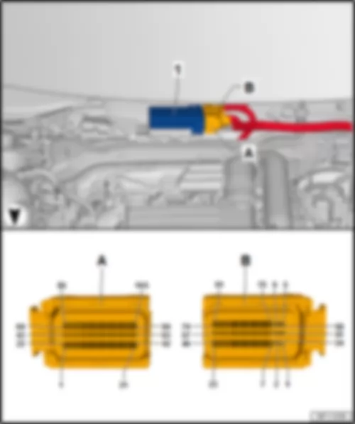
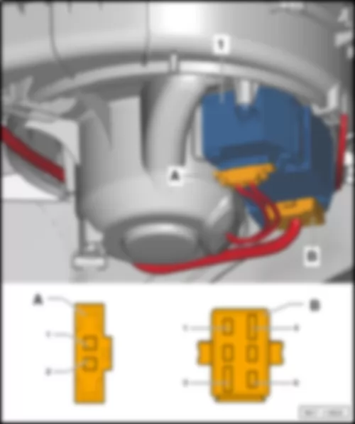
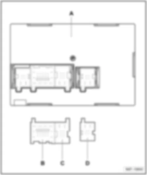
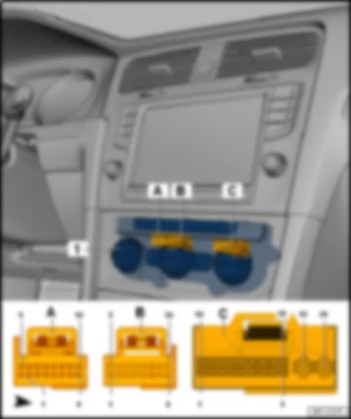
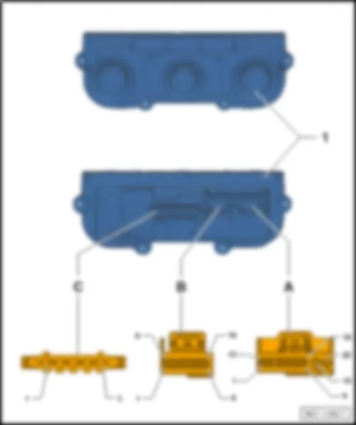
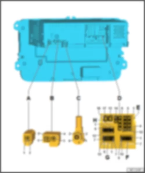
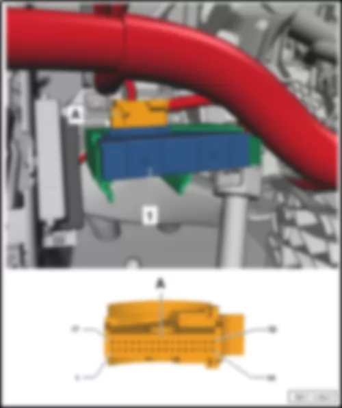
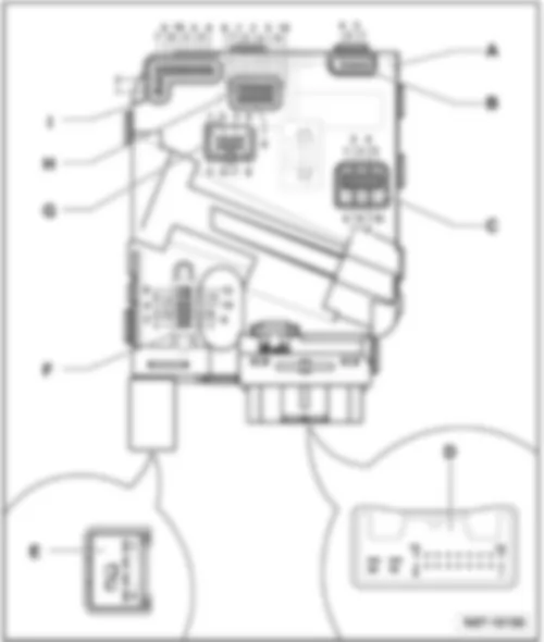
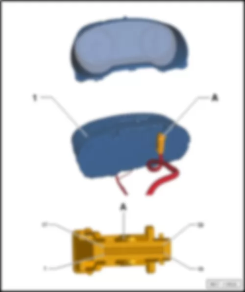
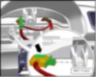
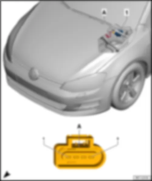
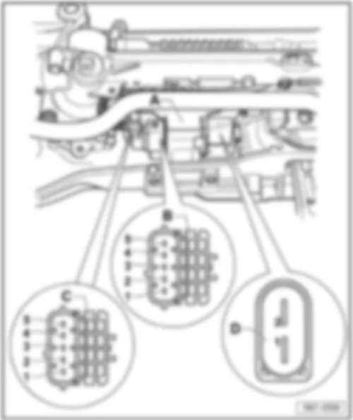
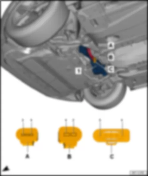
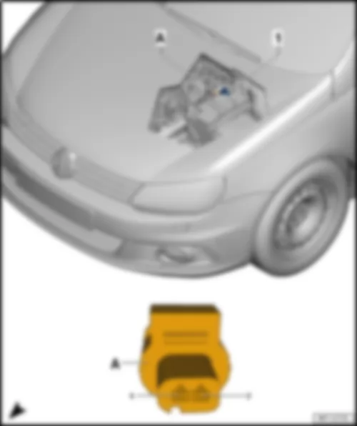
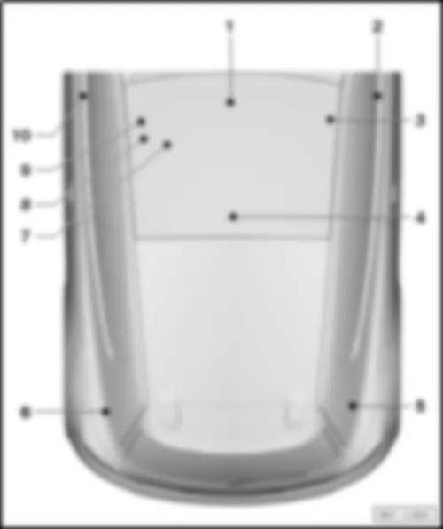
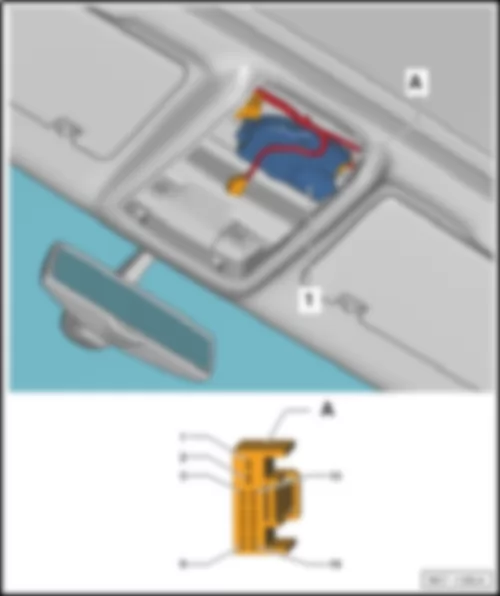
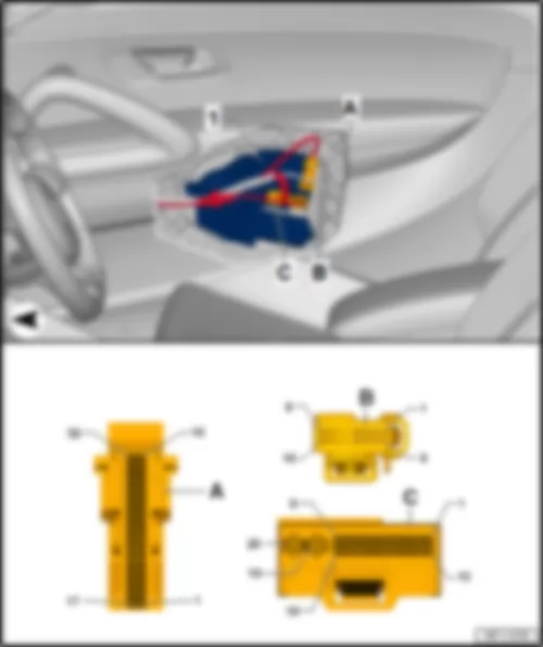
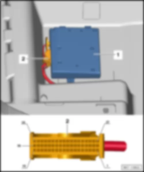
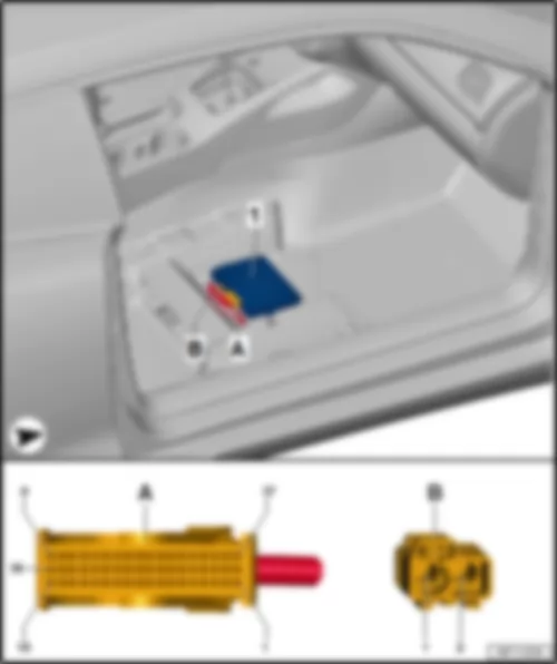
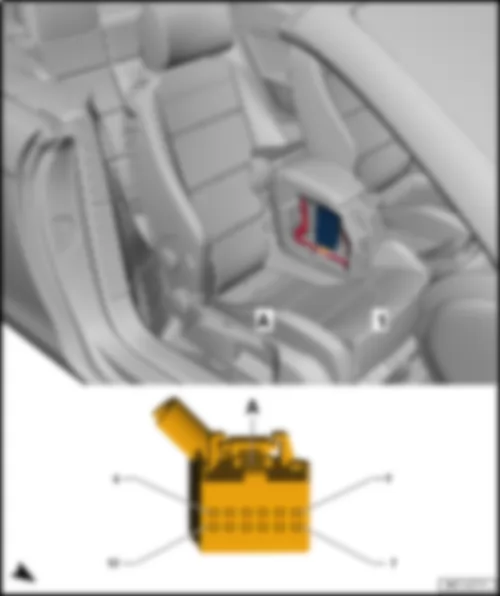
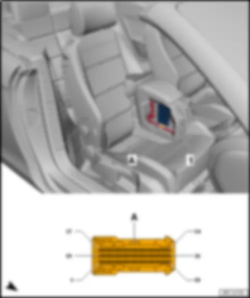
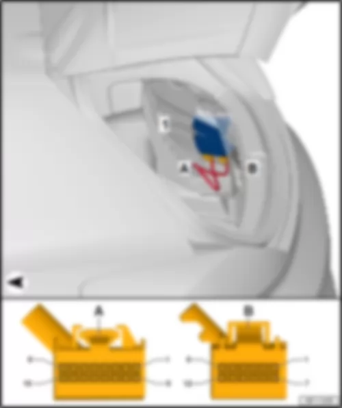
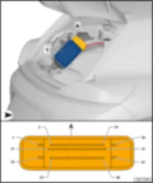
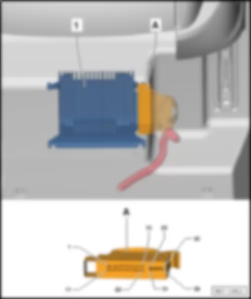
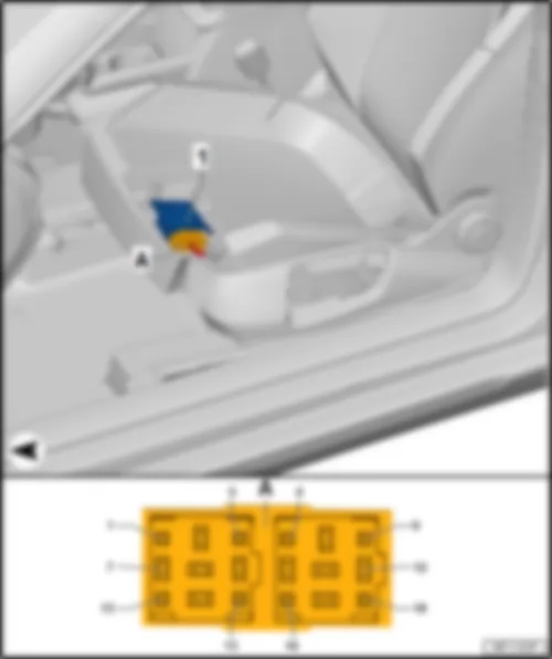
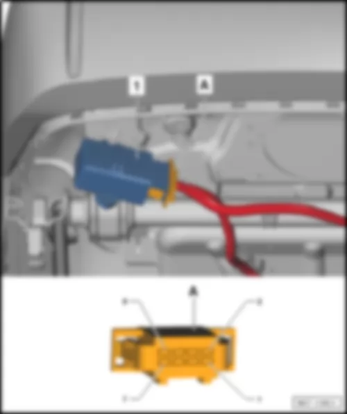
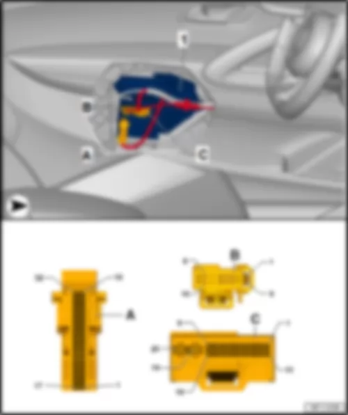
| 1 - | Control unit 1 for information electronics -J794- | | q | with multimedia system operating unit -E380- and display unit for front information display and operating unit control unit -J685- | | A - | 2-pin connector -T2fw- , black | | q | DAB aerial connection for impedance converter for rear right window aerial -R236- , digital radio aerial -R183- | | B - | 4-pin connector -T4by- , white | | q | AM/FM aerial connection for impedance converter for rear left window aerial -R235- , aerial -R11- | | q | FM2 aerial connection for impedance converter for rear right window aerial -R236- , radio aerial 2 -R93- | | C - | 2-pin connector -T2fx- , blue | | q | GPS aerial connection for GPS aerial -R50- in the roof aerial -RX5- | | D - | 5-pin connector -T5af- , yellow | | q | to connection for external audio sources -R199- | | E - | 8-pin connector -T8ab- , black | | F - | 8-pin connector -T8ac- , brown | | G - | 12-pin connector -T12ac- , blue | | H - | 12-pin connector -T12ab- , green | | J - | 12-pin connector -T12aa- , grey |
| Connector assignment, control unit 1 for information electronics -J794- | | -T8ac- (F) | Designation | | -T8ab- (E) | Designation | | 1 | Rear right treble loudspeaker -R16- , +1)
Rear right bass loudspeaker -R17- , +1)
Amplifier -R12-2) | | 9 | | | 2 | Front right treble loudspeaker -R22- , +1)
Front right bass loudspeaker -R23- , +1)
Amplifier -R12-2) | | 10 | | | 3 | Front left treble loudspeaker -R20- , +1)
Front left bass loudspeaker -R21- , +1)
Amplifier -R12-2) | | 11 | | | 4 | Rear left treble loudspeaker -R14- , +1)
Rear left bass loudspeaker -R15- , +1)
Amplifier -R12-2) | | 12 | | | 5 | Rear right treble loudspeaker -R16- , -1)
Rear right bass loudspeaker -R17- , -1)
Amplifier -R12-2) | | 13 | | | 6 | Front right treble loudspeaker -R22- , -1)
Front right bass loudspeaker -R23- , -1)
Amplifier -R12-2) | | 14 | | | 7 | Front left treble loudspeaker -R20- , -1)
Front left bass loudspeaker -R21- , -1)
Amplifier -R12-2) | | 17 | Terminal 31 | | 8 | Rear left treble loudspeaker -R14- , -1)
Rear left bass loudspeaker -R15- , -1)
Amplifier -R12-2) | | 18 | Terminal 30 |
| 1) Only for vehicles without an amplifier -R12- | | 2) Only for vehicles with an amplifier -R12- | | -T12aa- (J) | Designation | | -T12ab- (H) | Designation | | -T12ac- (G) | Designation | | 1 | | | 1 | Connection for external audio sources -R199- | | 1 | Telephone microphone -R38- | | 2 | | | 2 | Connection for external audio sources -R199- | | 2 | | | 3 | | | 3 | Connection for external audio sources -R199- | | 3 | | | 4 | | | 4 | Connection for external audio sources -R199- | | 4 | | | 5 | | | 5 | | | 5 | | | 6 | A178 Connection (infotainment CAN bus, high), in dash panel wiring harness | | 6 | | | 6 | Reversing camera -R189- | | 7 | | | 7 | Connection for external audio sources -R199- | | 7 | Telephone microphone -R38- | | 8 | | | 8 | Connection for external audio sources -R199- | | 8 | | | 9 | | | 9 | | | 9 | | | 10 | | | 10 | | | 10 | | | 11 | | | 11 | | | 11 | | | 12 | A179 Connection (infotainment CAN bus, low), in dash panel wiring harness | | 12 | | | 12 | Reversing camera -R189- |
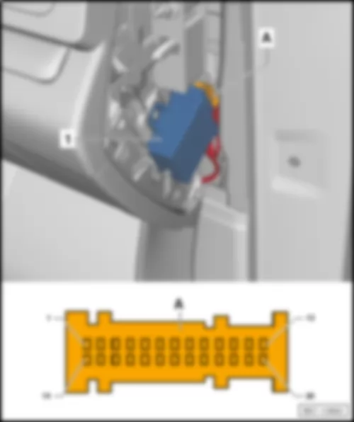
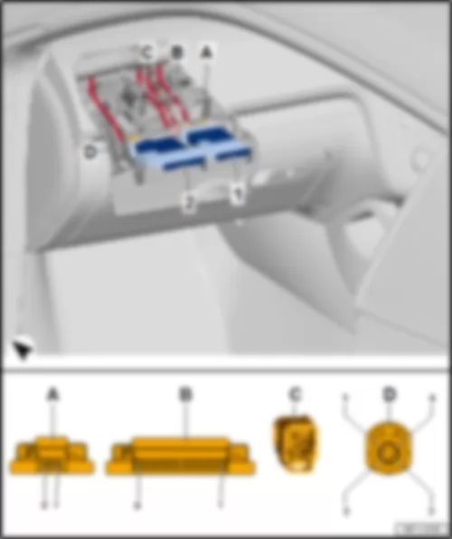
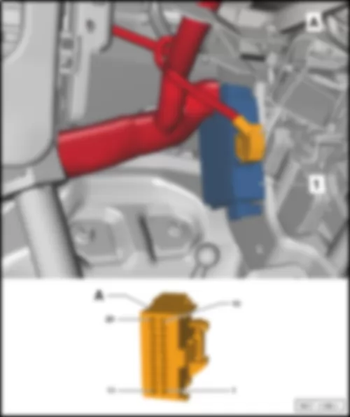
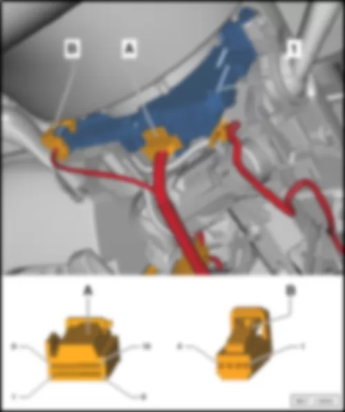
| Data bus diagnostic interface -J533- | | in driver's footwell, near centre console | | 1 - | Data bus diagnostic interface -J533- | | A - | 20-pin connector -T20- |
VW PASSAT CC 2009 Entry and start authorisation control unit J518Entry and start authorisation control unit -J518- |
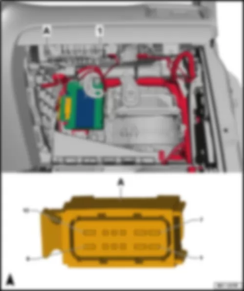
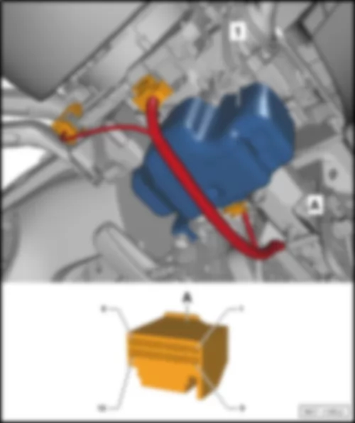
| next to steering column, near centre console | | 1 - | Entry and start authorisation control unit -J518- | | A - | 32-pin connector -T32e- |
VW PASSAT CC 2009 Multifunction steering wheel control unit -J453- , up to April 2014 |
| | | | In multifunction steering wheel -arrow- | | | |
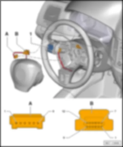
VW PASSAT CC 2009 Multifunction steering wheel control unit -J453- , from May 2014 |
| in multifunction steering wheel | | 1 - | Multifunction steering wheel control unit -J453- | | B - | 12-pin connector -T12- |
VW PASSAT CC 2009 Steering column electronics control unit -J527- , up to April 2009 |
| | | | under steering column, near steering column switch -arrow- | | | | | Connector assignment of steering column electronics control unit -J527- : | | A - | Steering column electronics control unit -J527- | | B - | 4-pin connector -T4- for airbag | | C - | 10-pin connector -T10- for turn signal switch -E2- /headlight dipper and flasher switch -E4- /cruise control system switch -E45- | | D - | 20-pin connector -T20d- | | E - | 4-pin connector -T4k- | | F - | 12-pin connector -T12j- /ignition/starter switch -D- /ignition key withdrawal lock solenoid -N376- | | G - | 8-pin connector -T8- for intermittent wiper switch -E22- /intermittent wiper regulator -E38- /washer pump switch (automatic wash/wipe and headlight washer system) -E44- /multifunction display call-up button -E86- /reset button -E92- | | H - | 8-pin connector -T10- for steering angle sender -G85- | | I - | 10-pin connector -T10x- for coil connector -F350- /airbag coil connector and return ring with slip ring -F138- |
| T4 (B) | Designation | | T10 (C) | Designation | | T20d (D) | Designation | | 1 | Airbag 1- | | 1 | Cruise control system terminal 15 voltage supply | | 1 | not assigned | | 2 | Airbag 1+ | | 2 | CCS off | | 2 | not assigned | | 3 | Airbag 2+ | | 3 | Cruise control system (CCS) SET button -E227- Res (+), Set (-) | | 3 | not assigned | | 4 | Airbag 2- | | 4 | CCS on/off | | 4 | not assigned | | | | | 5 | Earth CCS | | 5 | not assigned | | | | | 6 | Cruise control system terminal 58 illumination | | 6 | not assigned | | | | | 7 | Headlight flasher | | 7 | not assigned | | | | | 8 | Main beam | | 8 | not assigned | | | | | 9 | Turn signal | | 9 | Onboard supply control unit -J519- terminal S 1 | | | | | 10 | Turn signal earth | | 10 | not assigned | | | | | | | | 11 | Data bus diagnostic interface -J533- /connection 1 (powertrain CAN bus, low), in main wiring harness -B390- | | | | | | | | 12 | Data bus diagnostic interface -J533- /connection 1 (powertrain CAN bus, high), in main wiring harness -B383- | | | | | | | | 13 | Engine control unit -J623- /connection (CCS), in main wiring harness -B441- | | | | | | | | 14 | Data bus diagnostic interface -J533- /connection 1 (convenience CAN bus, high), in main wiring harness -B397- | | | | | | | | 15 | Data bus diagnostic interface -J533- /connection 1 (convenience CAN bus, low), in main wiring harness -B406- | | | | | | | | 16 | Selector lever locked in position P switch -F319- | | | | | | | | 17 | Terminal 15 | | | | | | | | 18 | Terminal 50 | | | | | | | | 19 | Terminal 30 | | | | | | | | 20 | Terminal 31 |
| T4k (E) | Designation | | T12j (F) | Designation | | T8 (G) | Designation | | 1 | Airbag 1- | | 1 | not assigned | | 1 | Wiper switch signal | | 2 | Airbag 1+ | | 2 | not assigned | | 2 | Earth wiper | | 3 | Airbag 2+ | | 3 | 2-pin connector -T2dy- , ignition key withdrawal lock solenoid -N376- terminal 30 | | 3 | Rear lid wash/wipe signal | | 4 | Airbag 2- | | 4 | 2-pin connector -T2dy- , ignition key withdrawal lock solenoid -N376- earth | | 4 | not assigned | | | | | 5 | not assigned | | 5 | MFD signal | | | | | 6 | not assigned | | 6 | Earth MFD, interval potentiometer | | | | | 7 | Ignition/starter switch -D- , output terminal 50 | | 7 | Intermittent operation speeds signal | | | | | 8 | Ignition/starter switch -D- , terminal 30 | | 8 | not assigned | | | | | 9 | Ignition/starter switch -D- , output terminal S | | | | | | | | 10 | Ignition/starter switch -D- , output terminal X | | | | | | | | 11 | Ignition/starter switch -D- , output terminal P | | | | | | | | 12 | Ignition/starter switch -D- , output terminal 15 | | | |
| T10 (H) | Designation | | T10x (I) | Designation | | 1 | Photoelectric beam 5 | | 1 | not assigned | | 2 | Photoelectric beam 3 | | 2 | not assigned | | 3 | Photoelectric beam 1 | | 3 | Airbag 1 + | | 4 | 12 Volt voltage supply | | 4 | Airbag 1 - | | 5 | 5 Volt voltage supply | | 5 | Airbag 2 + | | 6 | Photoelectric beam 6 | | 6 | Airbag 2 - | | 7 | Photoelectric beam 4 | | 7 | Earth for coil connector, multifunction steering wheel and signal horn | | 8 | Photoelectric beam 2 | | 8 | CCS in detent -Off-, signal horn | | 9 | Earth | | 9 | LIN bus, heated steering wheel temperature sensor | | 10 | Photoelectric beam 7 | | 10 | Multifunction steering wheel voltage supply terminal 15 |
VW PASSAT CC 2009 Steering column electronics control unit -J527- , from May 2009 |
| under steering column, near steering column switch | | 1 - | Steering column electronics control unit -J527- | | A - | 16-pin connector -T16l- | | B - | 4-pin connector -T4k- |
VW PASSAT CC 2009 Control unit for electronic steering column lock J764Control unit for electronic steering column lock -J764- |
| behind steering column trim | | 1 - | Control unit for electronic steering column lock -J764- | | A - | 16-pin connector -T16ls- |
VW PASSAT CC 2009 Control unit in dash panel insert -J285- , up to April 2009 |
| Connector assignment of control unit in dash panel insert -J285- : | | T36 | Designation | | T36 | Designation | | T36 | Designation | | 1 | Fuse 14 on fuse holder C -SC2- terminal 15a | | 13 | Diagnostic interface for dash panel insert -J533- CAN data bus, high | | 25 | Oil pressure switch -F1- | | 2 | Fuse 6 on fuse holder B -SB6- terminal 30a | | 14 | not assigned | | 26 | Oil level and oil temperature sender -G266- | | 3 | not assigned | | 15 | Diagnostic interface for dash panel insert -J533- CAN data bus, wake-up wire | | 27 | not assigned | | 4 | not assigned | | 16 | not assigned | | 28 | not assigned | | 5 | Brake fluid level warning lamp -K33- | | 17 | Fuel gauge -G1- (full) | | 29 | not assigned | | 6 | Handbrake warning switch -F9- | | 18 | Fuel gauge -G1- (empty) | | 30 | not assigned | | 7 | Immobiliser reader coil -D2- | | 19 | Earth connection 2, in main wiring harness -367- terminal 31 | | 31 | not assigned | | 8 | Immobiliser reader coil -D2- | | 20 | not assigned | | 32 | not assigned | | 9 | not assigned | | 21 | not assigned | | 33 | Earth connection (sender earth), in interior wiring harness -401- | | 10 | not assigned | | 22 | Front left brake pad wear sender -G34- | | 34 | Windscreen washer fluid level sender -G33- | | 11 | not assigned | | 23 | not assigned | | 35 | Coolant shortage indicator sender -G32- | | 12 | Diagnostic interface for dash panel insert -J533- CAN data bus, low | | 24 | not assigned | | 36 | Ambient temperature sensor -G17- |
VW PASSAT CC 2009 Control unit in dash panel insert -J285- , from May 2009 |
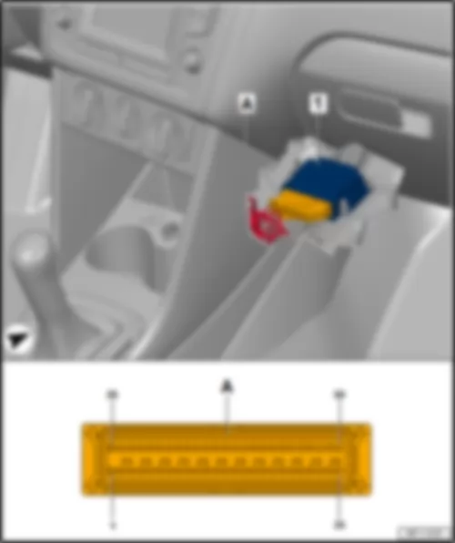
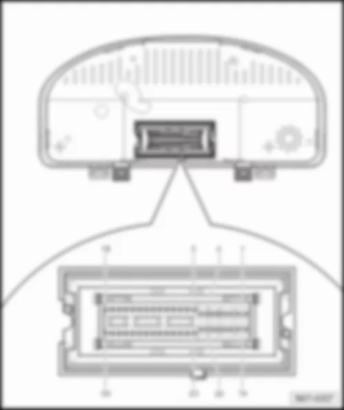
| 1 - | Control unit in dash panel insert -J285- | | A - | 32-pin connector -T32- |
| Connector assignment of control unit in dash panel insert -J285- : | | T32 | Designation | | T32 | Designation | | T32 | Designation | | 1 | Fuel gauge sender -G- (full) | | 12 | not assigned | | 23 | not assigned | | 2 | Fuel gauge sender -G- (empty) | | 13 | not assigned | | 24 | not assigned | | 3 | not assigned | | 14 | not assigned | | 25 | Handbrake warning lamp -K139- | | 4 | not assigned | | 15 | Front left brake pad wear sender -G34- | | 26 | Brake fluid level warning lamp -K33- | | 5 | not assigned | | 16 | Earth connection 22, in main wiring harness -367- | | 27 | Oil pressure warning lamp -K3- | | 6 | not assigned | | 17 | Washer fluid level warning lamp -K37- | | 28 | Diagnostic interface for dash panel insert -J533- CAN data bus, high | | 7 | Immobiliser reader coil -D2- | | 18 | Coolant temperature and coolant shortage warning lamp -K28- | | 29 | Diagnostic interface for dash panel insert -J533- CAN data bus, low | | 8 | Immobiliser reader coil 2 -D3- | | 19 | Ambient temperature sensor -G17- | | 30 | not assigned | | 9 | Sliding sunroof adjustment control unit -J245- , speed signal, output | | 20 | Earth connection 1 (sender earth) in main wiring harness -410- | | 31 | Fuse 2 on fuse holder C -SC2- terminal 15a | | 10 | not assigned | | 21 | not assigned | | 32 | Fuse 6 on fuse holder B -SB6- terminal 30a | | 11 | Oil level and oil temperature sender -G266- | | 22 | not assigned | | | |
VW PASSAT CC 2009 Traffic data aerial R173Traffic data aerial -R173- |
| | | | Behind the dash panel insert -K--arrow- . |
VW PASSAT CC 2009 Onboard supply control unit -J519- , up to April 2009 |
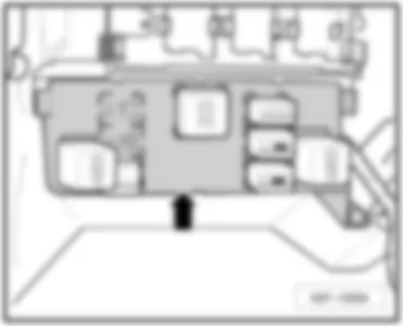
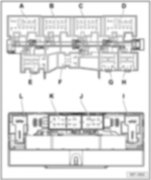
| | | | on left under dash panel, below relay carrier -arrow- | | | | | Connector assignment of onboard supply control unit -J519- : | | A - | 11-pin connector -T11b- | | B - | 12-pin connector -T12a- | | C - | 12-pin connector -T12m- | | D - | 11-pin connector -T11c- | | E - | 16-pin connector -T16k- | | F - | 8-pin connector -T8a- | | G - | 12-pin connector -T12n- | | H - | 12-pin connector -T12- | | I - | 2-pin connector -T2z- | | J - | 6-pin connector -T6l- | | K - | 10-pin connector -T10- | | L - | 2-pin connector -T2t- |
| T11b (A) | Designation | | T12a (B) | Designation | | T12m (C) | Designation | | 1 | Terminal 30 | | 1 | Rear fog light bulb | | 1 | Seat heating control unit | | 2 | Right dipped beam bulb/ right gas discharge light control unit | | 2 | not assigned | | 2 | Left brake light bulb | | 3 | Right main beam bulb (not for xenon) / right static cornering light (only for xenon) | | 3 | not assigned | | 3 | Left reversing light bulb | | 4 | Right fog light bulb -L23- | | 4 | Right reversing light bulb, automatic anti-dazzle interior mirror | | 4 | not assigned | | 5 | Right dipped beam screen motor (xenon) | | 5 | Right brake light bulb | | 5 | not assigned | | 6 | Front right turn signal bulb | | 6 | not assigned | | 6 | not assigned | | 7 | Left side light bulb | | 7 | Footwell lighting bulb front left, footwell lighting bulb front right | | 7 | not assigned | | 8 | Power output module for left gas discharge headlight | | 8 | not assigned | | 8 | Number plate light | | 9 | Earth | | 9 | Right tail light bulb | | 9 | High-level brake light bulb | | 10 | Fuel pump control unit | | 10 | Rear right turn signal bulb | | 10 | Left tail light bulb | | 11 | Terminal 50 voltage supply relay | | 11 | Front interior light, button illumination bulb | | 11 | Rear left turn signal bulb | | | | | 12 | Terminal 58d | | 12 | Left reversing light bulb (only models without rear left fog light bulb) |
| T11c (D) | Designation | | T16k (E) | Designation | | T8a (F) | Designation | | 1 | Terminal 30 | | 1 | Lighting switch terminal 58 | | 1 | Terminal 50 voltage supply relay | | 2 | Left fog light bulb | | 2 | Brake light switch | | 2 | not assigned | | 3 | Left main beam headlight, dipped beam | | 3 | not assigned | | 3 | Windscreen wiper motor, rain and light sensor (LIN bus) | | 4 | Left dipped beam bulb | | 4 | not assigned | | 4 | Alternator | | 5 | Earth | | 5 | not assigned | | 5 | Bonnet contact switch | | 6 | Left dip beam screen motor | | 6 | Fog light switch | | 6 | not assigned | | 7 | not assigned | | 7 | Earth (only models with manual gearbox for American markets) | | 7 | Terminal 30 | | 8 | Headlight washer system relay | | 8 | Lighting switch terminal 56 | | 8 | Terminal 31 | | 9 | Right gas discharge headlight | | 9 | not assigned | | | | | 10 | Right side light bulb | | 10 | not assigned | | | | | 11 | Left side light bulb | | 11 | not assigned | | | | | | | | 12 | not assigned | | | | | | | | 13 | Rear fog light switch | | | | | | | | 14 | Light switch, driving light assist | | | | | | | | 15 | not assigned | | | | | | | | 16 | Light switch | | | |
| T12n (G) | Designation | | T2z (I) | Designation | | T6l (J) | Designation | | 1 | Steering column electronics control unit terminal 50 | | 1 | Fuses terminal 30 | | 1 | Washer pump fuse | | 2 | Indicator lamp for hazard warning light | | 2 | Terminal 75a | | 2 | Washer pump | | 3 | not assigned | | | | | 3 | Horn fuse | | 4 | Instrument illumination regulator | | | | | 4 | Washer pump | | 5 | not assigned | | | | | 5 | Earth | | 6 | not assigned | | | | | 6 | Treble tone horn, bass tone horn | | 7 | Convenience CAN bus low | | | | | | | | 8 | Convenience CAN bus high | | | | | | | | 9 | Hazard warning light switch | | | | | | | | 10 | Instrument illumination regulator | | | | | | | | 11 | Steering column electronics control unit terminal 15 | | | | | | | | 12 | Instrument illumination regulator | | | | | | |
| T10 (K) | Designation | | T2t (L) | Designation | | 1 | Heated rear window | | 1 | Fuse 28 on fuse holder B -SB28- terminal 30 | | 2 | not assigned | | 2 | Interior terminal 15 | | 3 | not assigned | | | | | 4 | not assigned | | | | | 5 | Fuse terminal 30 | | | | | 6 | Heated rear window | | | | | 7 | not assigned | | | | | 8 | not assigned | | | | | 9 | not assigned | | | | | 10 | Terminal 30g | | | |
VW PASSAT CC 2009 Onboard supply control unit -J519- (BCM), from May 2009 |
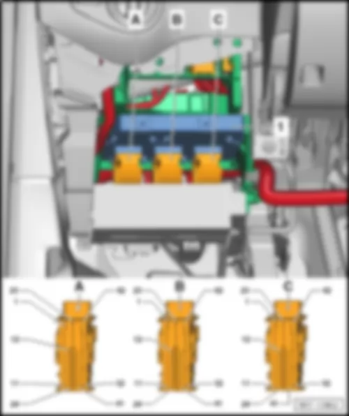
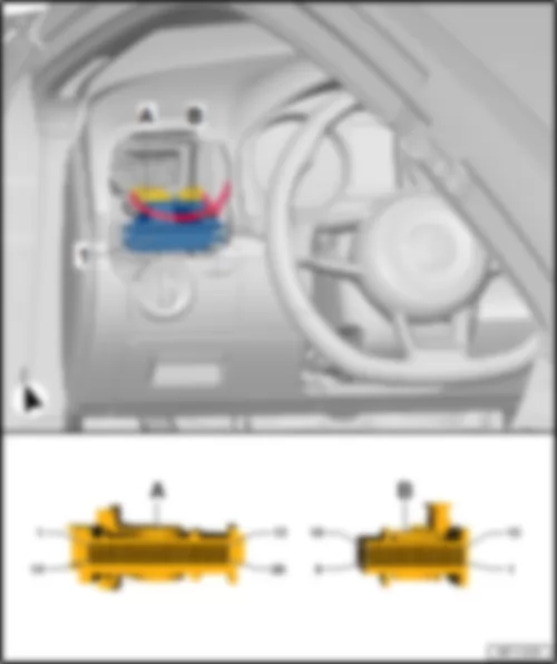
Note: | The depicted vehicle model does not correspond with the actual vehicle model. The fitting location is identical in the actual vehicle model, however. | | under dash panel on driver side, under relay carrier | | 1 - | Onboard supply control unit -J519- | | A - | 52-pin connector -T52a- , black | | B - | 52-pin connector -T52b- , white | | C - | 52-pin connector -T52c- , brown |
| Connector assignment of onboard supply control unit -J519- : | | T52a (A) | Designation | | T52b (B) | Designation | | T52c (C) | Designation | | 1 | Fuse 26 on fuse holder B -SB26- | | 1 | Fuse 38 on fuse holder C -SC38- , central locking | | 1 | not assigned | | 2 | not assigned | | 2 | Rear window wiper motor -V12- , windscreen and rear window washer pump -V59- | | 2 | not assigned | | 3 | not assigned | | 3 | not assigned | | 3 | Right tail light bulb -M2- | | 4 | Right washer jet heater element -Z21- , left washer jet heater element -Z20- | | 4 | not assigned | | 4 | Left brake light bulb -M9- | | 5 | Left headlight main beam bulb -M30- , left static cornering light -M51- | | 5 | Tank filler flap locking motor -V155- | | 5 | Earth connection 1, in main wiring harness -366- | | 6 | Left tail light bulb -M4- , right rear fog lamp bulb -L47- | | 6 | not assigned | | 6 | not assigned | | 7 | Left daytime running light bulb -L174- | | 7 | not assigned | | 7 | Hazard warning light switch -E3- | | 8 | Right daytime running light bulb -L175- | | 8 | not assigned | | 8 | not assigned | | 9 | Rear right turn signal bulb -M8- | | 9 | not assigned | | 9 | not assigned | | 10 | Front left turn signal bulb -M5- | | 10 | not assigned | | 10 | Front interior light -W1- , button for deactivating interior monitoring and vehicle inclination sensor -E616- | | 11 | Left gas discharge bulb control unit -J343- , left headlight dipped beam bulb -M29- | | 11 | Rear lid release motor -V139- | | 11 | not assigned | | 12 | Rear lid lock unit -F256- , luggage compartment light switch -F5- , luggage compartment light -W3- | | 12 | Terminal 15 voltage supply relay 2 -J681- | | 12 | not assigned | | 13 | not assigned | | 13 | not assigned | | 13 | Steering column electronics control unit -J527- , ignition/starter switch -D- , terminal S | | 14 | Bonnet contact switch -F266- | | 14 | not assigned | | 14 | Positive connection (50), in main wiring harness -B276- , steering column electronics control unit -J527- | | 15 | not assigned | | 15 | Switch and instrument illumination regulator -E20- | | 15 | Data bus diagnostic interface -J533- , connection 1 (convenience CAN bus, high), in main wiring harness -B397- | | 16 | Reversing light switch -F4- | | 16 | not assigned | | 16 | Data bus diagnostic interface -J533- , connection 1 (convenience CAN bus, low), in main wiring harness -B406- | | 17 | Rear fog light switch -E18- | | 17 | not assigned | | 17 | Brake light switch -F- | | 18 | Light switch -E1- , 0 position | | 18 | not assigned | | 18 | not assigned | | 19 | Light switch -E1- , side light | | 19 | not assigned | | 19 | not assigned | | 20 | Light switch -E1- , driving light assist | | 20 | not assigned | | 20 | not assigned | | 21 | Fog light switch -E7- | | 21 | Heated front seats control unit -J774- | | 21 | not assigned | | 22 | Light switch -E1- , dip beam | | 22 | Heated rear window relay -J9- | | 22 | not assigned | | 23 | Earth connection 15, in main wiring harness-380- | | 23 | not assigned | | 23 | not assigned | | 24 | Fuse 3 on fuse holder B -SB3- , terminal 30ref | | 24 | Hazard warning lights button -E229- | | 24 | not assigned | | 25 | Left fog light bulb -L22- | | 25 | not assigned | | 25 | Right fog light bulb -L23- | | 26 | Right brake light bulb -M10- | | 26 | not assigned | | 26 | Front left side marker bulb -M33- | | 27 | Left tail light bulb -M4- | | 27 | not assigned | | 27 | Number plate light -X- | | 28 | Left reversing light bulb -M16- | | 28 | X-contact relief relay -J59- | | 28 | Right reversing light bulb -M17- , right rear fog lamp bulb -L47- | | 29 | Rear lid lock unit -F256- | | 29 | Terminal 50 voltage supply relay -J682- | | 29 | not assigned | | 30 | not assigned | | 30 | Switch and instrument illumination regulator -E20- | | 30 | Mechatronic unit for dual clutch gearbox -J743- interlock, earth connection 17, in main wiring harness -382- manual gearbox | | 31 | not assigned | | 31 | not assigned | | 31 | Steering column electronics control unit -J527- , potential 15 | | 32 | not assigned | | 32 | not assigned | | 32 | DC/AC converter with socket, 12 V - 230 V -U13- , potential 61, without start/stop function, heater operating and display unit1 | | 33 | not assigned | | 33 | Wiper motor control unit -J400-Rain and light sensor -G397- , LIN bus | | 33 | not assigned | | 34 | not assigned | | 34 | not assigned | | 34 | Positive connection (50), in dash panel wiring harness -A41- | | 35 | not assigned | | 35 | not assigned | | 35 | Switch and instrument illumination regulator -E20- | | 36 | Button for deactivating interior monitoring and vehicle inclination sensor -E616- | | 36 | Alarm horn -H12- , interior monitoring sensor -G273- , vehicle inclination sender -G384- | | 36 | not assigned | | 37 | not assigned | | 37 | Button for deactivating interior monitoring and vehicle inclination sensor -E616- , interior monitoring off warning lamp -K162- | | 37 | not assigned | | 38 | not assigned | | 38 | Fuel pump control unit -J538- , fuel supply relay -J643- | | 38 | not assigned | | 39 | not assigned | | 39 | not assigned | | 39 | not assigned | | 40 | not assigned | | 40 | Headlight washer system relay -J39- | | 40 | not assigned | | 41 | not assigned | | 41 | Dual tone horn relay -J4- | | 41 | not assigned | | 42 | Earth connection 19, in main wiring harness -384- | | 42 | Fuse 24 on fuse holder C -SC24- | | 42 | Fuse 16 on fuse holder B -SB16- | | 43 | Rear window wiper motor -V12- , windscreen and rear window washer pump -V59- | | 43 | Positive connection 1 (30g), in main wiring harness -B559- | | 43 | not assigned | | 44 | Front right side marker bulb -M34- | | 44 | not assigned | | 44 | not assigned | | 45 | High-level brake light bulb -M25- | | 45 | not assigned | | 45 | not assigned | | 46 | Tank filler flap locking motor -V155- | | 46 | not assigned | | 46 | Right headlight main beam bulb -M32- | | 47 | not assigned | | 47 | not assigned | | 47 | Rear left fog light bulb -L46- | | 48 | not assigned | | 48 | not assigned | | 48 | Left main and dip beam switch-over solenoid -N347- | | 49 | not assigned | | 49 | not assigned | | 49 | Right main and dip beam switch-over solenoid -N348- | | 50 | not assigned | | 50 | Left footwell light -W9-Right footwell light -W10- | | 50 | Front right turn signal bulb -M7- | | 51 | not assigned | | 51 | Connection 1 (58d), in main wiring harness -B340- | | 51 | Rear left turn signal bulb -M6- | | 52 | not assigned | | 52 | Earth connection 1, in main wiring harness -366- | | 52 | Right headlight dipped beam bulb -M31- |
| 1 Only models with start/stop and energy recovery function |
VW PASSAT CC 2009 Parking aid control unit -J446- /park assist steering control unit -J791- |
Note: | t | The fitting location shown for the parking aid control unit -J446- applies to models from May 2014. | | t | In models up to May 2014, the parking aid control unit -J446- is fitted on the right in the luggage compartment behind the side trim. | | under dash panel on driver side, above relay carrier | | 1 - | Parking aid control unit -J446- /park assist steering control unit -J791- | | A - | 26-pin connector -T26- | | B - | 18-pin connector -T18- |
VW PASSAT CC 2009 Wiper motor control unit J400Wiper motor control unit -J400- |
Note: | The depicted vehicle model does not correspond with the actual vehicle model. The fitting location is identical in the actual vehicle model, however. | | In driver side plenum chamber. | | 1 - | Wiper motor control unit -J400- | | A - | 4-pin connector -T4q- |
VW PASSAT CC 2009 Power steering control unit -J500- , up to April 2009 |
| | | | on steering on centre of assembly carrier -arrow- | | | | | Connector assignment of power steering control unit -J500- : | | A - | Power steering control unit -J500- | | B - | 5-pin connector -T5g- | | C - | 5-pin connector -T5h- | | D - | 2-pin connector -T2a- |
VW PASSAT CC 2009 Power steering control unit -J500- , from May 2009 |
| on steering on centre of assembly carrier | | 1 - | Power steering control unit -J500- | | A - | 3-pin connector -T3be- | | B - | 2-pin connector -T2a- | | C - | 5-pin connector -T5ab- |
VW PASSAT CC 2009 Battery monitor control unit J367Battery monitor control unit -J367- |
Note: | The depicted vehicle model does not correspond with the actual vehicle model. The fitting location is identical in the actual vehicle model, however. | | 1 - | Battery monitor control unit -J367- | | A - | 2-pin connector -T2fj- |
VW PASSAT CC 2009 Mechatronic unit for dual clutch gearbox J743Mechatronic unit for dual clutch gearbox -J743- |
| | | | 1 - | Mechatronic unit for dual clutch gearbox -J743- | | A - | 20-pin connector -T20e- |
| 1 - | Mechatronic unit for dual clutch gearbox -J743- | | A - | 25-pin connector -T25- |
| | |

