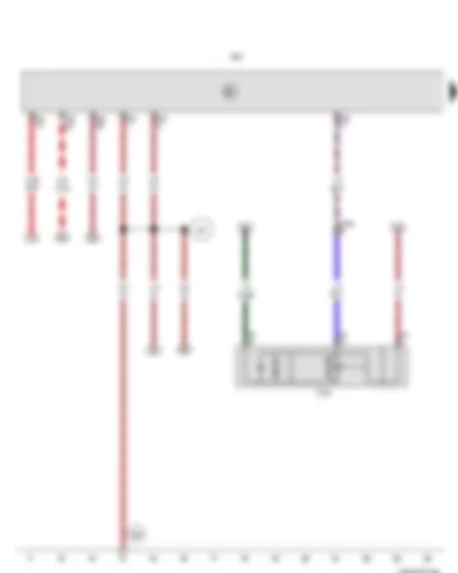
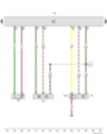
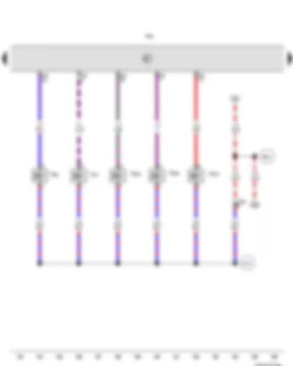
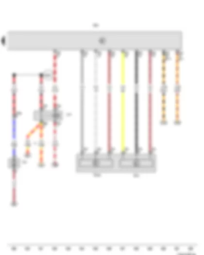
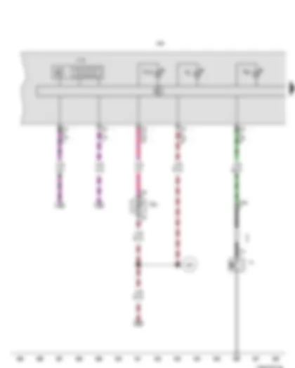
Wiring Diagram VW NEW BORA 2016 - Battery - Starter - Alternator - Voltage regulator - Fuse 1 in fuse holder A

| A | Battery |
| B | Starter |
| C | Alternator |
| C1 | Voltage regulator |
| D | Ignition/starter switch |
| SA1 | Fuse 1 in fuse holder A |
| T1 | Single connector |
| T2 | 2-pin connector |
| T4 | 4-pin connector |
| T6ag | 6-pin connector |
| 1 | Earth strap, battery - body |
| 290 | Earth connection 1, in second battery wiring harness |
| 507 | Threaded connection (30), on battery fuse holder |
| 652 | Earth point, engine and gearbox earth |
| B239 | Positive connection 1 (50), in interior wiring harness |
| * | Only models with manual gearbox |
| *2 | Up to February 2014 |
| *3 | According to equipment |
| *4 | Only models with dual clutch gearbox |
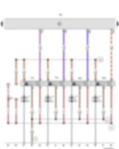
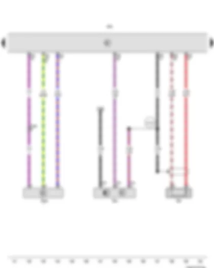
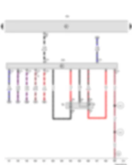
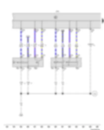
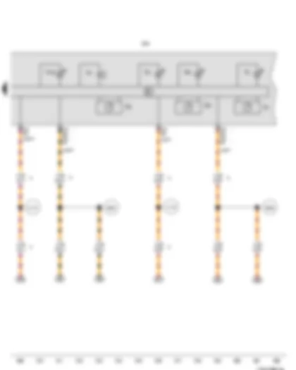
Wiring Diagram VW NEW BORA 2016 - Terminal 30 voltage supply relay - Terminal 15 voltage supply relay - Fuse 3 in fuse holder A - Fuse 6 in fuse holder A
| D | Ignition/starter switch |
| J317 | Terminal 30 voltage supply relay |
| J329 | Terminal 15 voltage supply relay |
| J935 | Converter box |
| SA3 | Fuse 3 in fuse holder A |
| SB6 | Fuse 6 on fuse holder B |
| SA6 | Fuse 6 in fuse holder A |
| T6ag | 6-pin connector |
| T10z | 10-pin connector |
| 507 | Threaded connection (30), on battery fuse holder |
| A32 | Positive connection (30), in dash panel wiring harness |
| A52 | Positive connection 2 (30), in dash panel wiring harness |
| A57 | Positive connection 3 (30), in dash panel wiring harness |
| A98 | Positive connection 4 (30), in dash panel wiring harness |
| B346 | Connection 1 (75), in main wiring harness |
| * | According to equipment |
| *2 | Cross section depends on equipment |
| *3 | Up to February 2014 |
| *4 | Up to July 2014 |
| *5 | From February 2014 |
| *6 | From July 2014 |
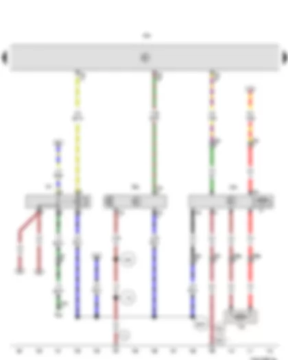
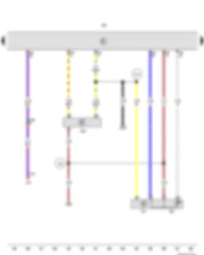
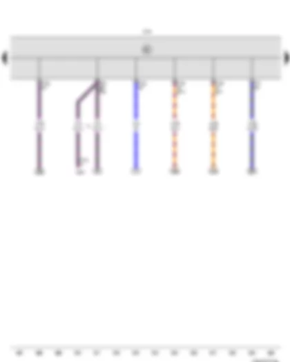
Wiring Diagram VW NEW BORA 2016 - Terminal 50 voltage supply relay - Fuse 2 on fuse holder B - Fuse 4 in fuse holder A
| J682 | Terminal 50 voltage supply relay |
| J764 | Control unit for electronic steering column lock |
| J935 | Converter box |
| SB2 | Fuse 2 on fuse holder B |
| SA4 | Fuse 4 in fuse holder A |
| T10z | 10-pin connector |
| T16h | 16-pin connector |
| 44 | Earth point, lower part of left A-pillar |
| 373 | Earth connection 8, in main wiring harness |
| 374 | Earth connection 9, in main wiring harness |
| 382 | Earth connection 17, in main wiring harness |
| 507 | Threaded connection (30), on battery fuse holder |
| 605 | Earth point, on top end of steering column |
| A40 | Positive connection 1 (30), in dash panel wiring harness |
| B240 | Positive connection 2 (50), in interior wiring harness |
| B276 | Positive connection (50), in main wiring harness |
| * | According to equipment |
| *2 | Up to February 2014 |
| *3 | From September 2012 |
| *4 | From February 2014 |
| *5 | Only models with entry and start authorisation |
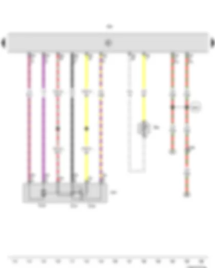
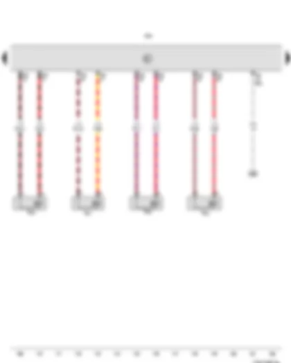
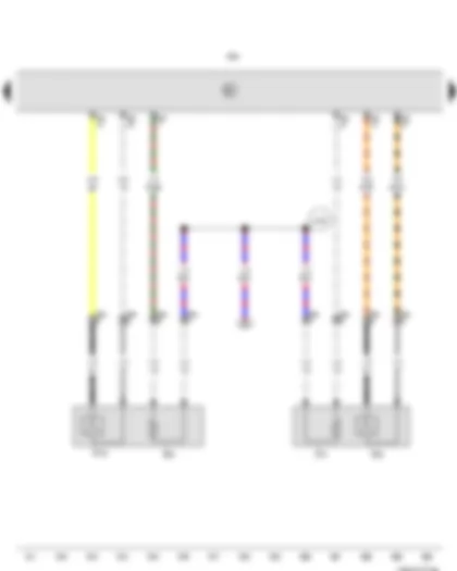
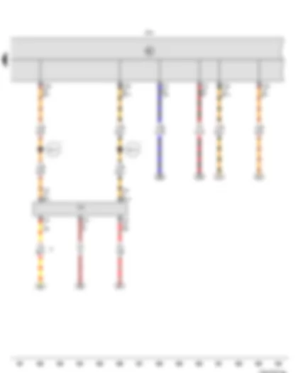
Wiring Diagram VW NEW BORA 2016 - Fuse holder C
| SC | Fuse holder C |
| SC21 | Fuse 21 on fuse holder C |
| SC22 | Fuse 22 on fuse holder C |
| SC23 | Fuse 23 on fuse holder C |
| SC24 | Fuse 24 on fuse holder C |
| SC25 | Fuse 25 on fuse holder C |
| SC26 | Fuse 26 on fuse holder C |
| A99 | Connection 1 (87) in dash panel wiring harness |
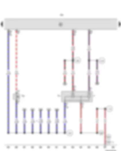
Wiring Diagram VW NEW BORA 2016 - Fuse holder C
| D | Ignition/starter switch |
| SC | Fuse holder C |
| SC1 | Fuse 1 on fuse holder C |
| SC2 | Fuse 2 on fuse holder C |
| SC14 | Fuse 14 on fuse holder C |
| SC27 | Fuse 27 on fuse holder C |
| SC28 | Fuse 28 on fuse holder C |
| SC45 | Fuse 45 on fuse holder C |
| T8f | 8-pin connector |
| A1 | Positive connection (30a), in dash panel wiring harness |
| A2 | Positive connection (15), in dash panel wiring harness |
| A200 | Positive connection 5 (15a) in dash panel wiring harness |
| D78 | Positive connection 1 (30a), in engine compartment wiring harness |
| * | According to equipment |
| *2 | Wiring colour depends on equipment |
| *3 | From February 2014 |
Wiring Diagram VW NEW BORA 2016 - Engine control unit - Vacuum pump for brakes
| J623 | Engine control unit |
| T6 | 6-pin connector |
| T14a | 14-pin connector |
| T60 | 60-pin connector |
| T94 | 94-pin connector |
| V192 | Vacuum pump for brakes |
| 367 | Earth connection 2, in main wiring harness |
| 608 | Earth point, central in plenum chamber |
| * | According to equipment |
Wiring Diagram VW NEW BORA 2016 - Engine control unit - Ignition coil 1 with output stage - Ignition coil 2 with output stage - Ignition coil 3 with output stage - Ignition coil 4 with output stage - Spark plug connector - Spark plugs
| J623 | Engine control unit |
| N70 | Ignition coil 1 with output stage |
| N127 | Ignition coil 2 with output stage |
| N291 | Ignition coil 3 with output stage |
| N292 | Ignition coil 4 with output stage |
| P | Spark plug connector |
| Q | Spark plugs |
| T14a | 14-pin connector |
| T60 | 60-pin connector |
| 15 | Earth point, on cylinder head |
| 85 | Earth connection 1, in engine compartment wiring harness |
| 281 | Earth point 1, engine prewiring harness |
| D20 | Connection (87a), in front right wiring harness |
Wiring Diagram VW NEW BORA 2016 - High-pressure sender - Air conditioning system relay - Radiator fan control unit - Engine control unit - Radiator fan - Right radiator fan
| G65 | High-pressure sender |
| J32 | Air conditioning system relay |
| J293 | Radiator fan control unit |
| J623 | Engine control unit |
| N25 | Air conditioning system magnetic clutch |
| T2ay | 2-pin connector |
| T2bg | 2-pin connector |
| T3a | 3-pin connector |
| T4 | 4-pin connector |
| T4b | 4-pin connector |
| T94 | 94-pin connector |
| V7 | Radiator fan |
| V35 | Right radiator fan |
| 13 | Earth point, on right in engine compartment |
| 176 | Earth connection, in right headlight wiring harness |
| 369 | Earth connection 4, in main wiring harness |
| 640 | Earth point 2, left in engine compartment |
| 655 | Earth point, on left headlight |
| B350 | Positive connection 1 (87a) in main wiring harness |
| * | Special equipment |
Wiring Diagram VW NEW BORA 2016 - Radiator outlet coolant temperature sender - Throttle valve drive for electric throttle - Throttle valve drive angle sender 1 for electric throttle - Throttle valve drive angle sender 2 for electric throttle - Throttle valve module - Engine control unit
| G83 | Radiator outlet coolant temperature sender |
| G186 | Throttle valve drive for electric throttle |
| G187 | Throttle valve drive angle sender 1 for electric throttle |
| G188 | Throttle valve drive angle sender 2 for electric throttle |
| J338 | Throttle valve module |
| J623 | Engine control unit |
| T6x | 6-pin connector |
| T14a | 14-pin connector |
| T60 | 60-pin connector |
| T94 | 94-pin connector |
| B353 | Positive connection 4 (87a) in main wiring harness |
| * | Cross section depends on equipment |
Wiring Diagram VW NEW BORA 2016 - Engine speed sender - Charge pressure sender - Coolant temperature sender - Intake air temperature sender 2 - Engine control unit
| G28 | Engine speed sender |
| G31 | Charge pressure sender |
| G62 | Coolant temperature sender |
| G299 | Intake air temperature sender 2 |
| J623 | Engine control unit |
| T60 | 60-pin connector |
| D107 | Connection 5 in engine compartment wiring harness |
Wiring Diagram VW NEW BORA 2016 - Hall sender - Knock sensor 1 - Brake servo pressure sensor - Engine control unit
| G40 | Hall sender |
| G61 | Knock sensor 1 |
| G294 | Brake servo pressure sensor |
| J623 | Engine control unit |
| T3d | 3-pin connector |
| T14a | 14-pin connector |
| T60 | 60-pin connector |
| T94 | 94-pin connector |
| D103 | Connection 3 in engine compartment wiring harness |
| * | According to equipment |
Wiring Diagram VW NEW BORA 2016 - Intake air temperature sender - Intake manifold pressure sender - Fuel pressure sender - Engine control unit
| G42 | Intake air temperature sender |
| G71 | Intake manifold pressure sender |
| G247 | Fuel pressure sender |
| J301 | Air conditioning system control unit |
| J623 | Engine control unit |
| T10e | 10-pin connector |
| T16d | 16-pin connector |
| T60 | 60-pin connector |
| T94 | 94-pin connector |
| 220 | Earth connection (sender earth), in engine wiring harness |
| D101 | Connection 1 in engine compartment wiring harness |
Wiring Diagram VW NEW BORA 2016 - Engine control unit - Injector - cylinder 1 - Injector - cylinder 2 - Injector - cylinder 3 - Injector - cylinder 4
| J623 | Engine control unit |
| N30 | Injector, cylinder 1 |
| N31 | Injector, cylinder 2 |
| N32 | Injector, cylinder 3 |
| N33 | Injector, cylinder 4 |
| T60 | 60-pin connector |
| T94 | 94-pin connector |
Wiring Diagram VW NEW BORA 2016 - Engine control unit - Charge pressure control solenoid valve - Activated charcoal filter solenoid valve 1 - Camshaft control valve 1 - Turbocharger air recirculation valve - Fuel pressure regulating valve
| J623 | Engine control unit |
| N75 | Charge pressure control solenoid valve |
| N80 | Activated charcoal filter solenoid valve 1 |
| N205 | Camshaft control valve 1 |
| N249 | Turbocharger air recirculation valve |
| N276 | Fuel pressure regulating valve |
| T14a | 14-pin connector |
| T60 | 60-pin connector |
| B351 | Positive connection 2 (87a) in main wiring harness |
| D181 | Connection 2 (87a) in engine compartment wiring harness |
Wiring Diagram VW NEW BORA 2016 - Fuel gauge sender - Fuel system pressurisation pump - Fuel pump control unit - Engine control unit
| G | Fuel gauge sender |
| G6 | Fuel system pressurisation pump |
| J538 | Fuel pump control unit |
| J623 | Engine control unit |
| T5a | 5-pin connector |
| T10n | 10-pin connector |
| T94 | 94-pin connector |
| 45 | Earth point, centre behind dash panel |
| 370 | Earth connection 5, in main wiring harness |
| 372 | Earth connection 7, in main wiring harness |
Wiring Diagram VW NEW BORA 2016 - Lambda probe - Lambda probe after catalytic converter - Engine control unit - Lambda probe heater - Lambda probe 1 heater after catalytic converter
| G39 | Lambda probe |
| G130 | Lambda probe after catalytic converter |
| J623 | Engine control unit |
| T4c | 4-pin connector |
| T4d | 4-pin connector |
| T94 | 94-pin connector |
| Z19 | Lambda probe heater |
| Z29 | Lambda probe 1 heater after catalytic converter |
| A193 | Connection (87a), in dash panel wiring harness |
Wiring Diagram VW NEW BORA 2016 - Brake light switch - Clutch pedal switch - Brake pedal switch - Engine control unit
| F | Brake light switch |
| F36 | Clutch pedal switch |
| F47 | Brake pedal switch |
| J623 | Engine control unit |
| T4f | 4-pin connector |
| T4h | 4-pin connector |
| T94 | 94-pin connector |
| 179 | Earth connection, in left headlight wiring harness |
| 366 | Earth connection 1, in main wiring harness |
| 640 | Earth point 2, left in engine compartment |
| 655 | Earth point, on left headlight |
| A20 | Positive connection (15a), in dash panel wiring harness |
| A89 | Connection 2 (54) in dash panel wiring harness |
| A154 | Connection (brake pedal switch), in dash panel wiring harness |
| * | Only models with manual gearbox |
| *2 | Special equipment |
| *3 | From February 2014 |
Wiring Diagram VW NEW BORA 2016 - Accelerator position sender - Accelerator position sender 2 - Continued coolant circulation relay - Engine control unit - Continued coolant circulation pump
| G79 | Accelerator position sender |
| G185 | Accelerator position sender 2 |
| J151 | Continued coolant circulation relay |
| J623 | Engine control unit |
| T5e | 5-pin connector |
| T6h | 6-pin connector |
| T14a | 14-pin connector |
| T94 | 94-pin connector |
| V51 | Continued coolant circulation pump |
| B354 | Positive connection 5 (87a) in main wiring harness |
| * | Up to February 2014 |
| *2 | From February 2014 |
Wiring Diagram VW NEW BORA 2016 - Cruise control system switch - Cruise control system (CCS) SET button - Onboard supply control unit
| E45 | Cruise control system switch |
| E227 | Cruise control system (CCS) SET button |
| J519 | Onboard supply control unit |
| T10j | 10-pin connector |
| T16j | 16-pin connector |
| T73a | 73-pin connector |
| A16 | Connection (CCS), in dash panel wiring harness |
| * | From February 2014 |
| *2 | Cross section depends on equipment |
| *3 | Up to February 2014 |
Wiring Diagram VW NEW BORA 2016 - Onboard supply control unit
| J519 | Onboard supply control unit |
| J935 | Converter box |
| T10z | 10-pin connector |
| T73 | 73-pin connector |
| T73a | 73-pin connector |
| * | Up to February 2014 |
| *2 | From February 2014 |
Wiring Diagram VW NEW BORA 2016 - Onboard supply control unit - Diagnostic connection
| J519 | Onboard supply control unit |
| T16 | 16-pin connector |
| T73 | 73-pin connector |
| T73a | 73-pin connector |
| U31 | Diagnostic connection |
| B713 | Connection 1 (CAN bus diagnosis, high), in main wiring harness |
| B714 | Connection 1 (CAN bus diagnosis, low), in main wiring harness |
| * | From February 2014 |
| *2 | Wiring colour depends on equipment |
Wiring Diagram VW NEW BORA 2016 - Oil pressure switch - Coolant shortage indicator sender - Control unit in dash panel insert
| F1 | Oil pressure switch |
| G32 | Coolant shortage indicator sender |
| J119 | Multifunction indicator |
| J285 | Control unit in dash panel insert |
| K3 | Oil pressure warning lamp |
| K28 | Coolant temperature and coolant shortage warning lamp |
| K132 | Electronic power control fault lamp |
| T1g | Single connector |
| T2s | 2-pin connector |
| T14a | 14-pin connector |
| T32 | 32-pin connector |
| 269 | Earth connection (sender earth) 1, in dash panel wiring harness |
| * | According to equipment |
| *2 | Cross section depends on equipment |
| *3 | Wiring colour depends on equipment |
Wiring Diagram VW NEW BORA 2016 - Control unit in dash panel insert
| G1 | Fuel gauge |
| G5 | Rev. counter |
| G21 | Speedometer |
| H3 | Buzzer and gong |
| J285 | Control unit in dash panel insert |
| K2 | Alternator warning lamp |
| K31 | Cruise control system warning lamp |
| K83 | Exhaust emissions warning lamp |
| K105 | Reserve fuel warning lamp |
| T32 | 32-pin connector |
| A178 | Connection (infotainment CAN bus, high), in dash panel wiring harness |
| A179 | Connection (infotainment CAN bus, low), in dash panel wiring harness |
| B383 | Connection 1 (powertrain CAN bus, high), in main wiring harness |
| B390 | Connection 1 (powertrain CAN bus, low), in main wiring harness |
| * | According to equipment |
| *2 | Only models with no Coming Home function |
| *3 | Only models with Coming Home function |
Can't find your car? Check -> DiagnostData.com!

