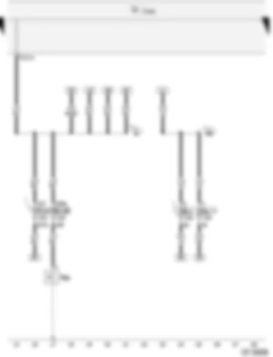
Wiring Diagram VW CITI GOLF 2005 - Battery - Starters - Alternator - Voltage regulator - Ignition/starter switch - Radiator fan thermal switch - Onboard power supply control unit

| A | Battery |
| B | Starters |
| C | Alternator |
| C1 | Voltage regulator |
| D | Ignition/starter switch |
| F18 | Radiator fan thermal switch |
| J519 | Onboard power supply control unit |
| R | Radio (01304) |
| SA1 | Fuse -1- on battery fuse holder |
| SA2 | Fuse -2- on battery fuse holder |
| T8 | 8-Pin Connector, black, radio connector |
| T12 | 12-Pin Connector, black |
| T28 | 28-Pin Connector, black |
| V7 | Radiator fan |
| 12 | Earth point, on left in engine compartment |
| 14 | Earth point, on gearbox |
| A32 | Positive connection (30), in dash panel wiring harness |
| A80 | Connection -1- (X), in dash panel wiring harness |
| D2 | Connection (temperature control switch), in front right wiring harness |
| * | After Market only |
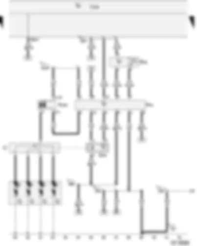
Wiring Diagram VW CITI GOLF 2005 - Onboard power supply control unit - Fuse in relay plate fuse box - Idling speed - overrun control valve
| J519 | Onboard power supply control unit |
| S3 | Fuse in relay plate fuse box |
| S4 | Fuse in relay plate fuse box |
| S227 | Fuse in fuse holder |
| S229 | Fuse in fuse holder |
| T12 | 12-Pin Connector, black |
| N68 | Idling speed, overrun control valve |
| A2 | Positive connection (15), in dash panel wiring harness |
| A52 | Positive connection -2- (30), in dash panel wiring harness |
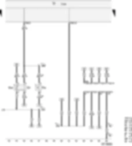
Wiring Diagram VW CITI GOLF 2005 - Onboard power supply control unit - Pressure sensor - Hall sender - TCI-H switch unit - Ignition transformer - Ignition distributor
| J519 | Onboard power supply control unit |
| G16 | Pressure sensor |
| G40 | Hall sender |
| N41 | TCI-H switch unit |
| N152 | Ignition transformer |
| O | Ignition distributor |
| P | Spark plug connectors |
| Q | Spark plug |
| T28 | 28-Pin Connector, black |
| 12 | Earth point, on left in engine compartment |
| 104 | Earth connection in front right wiring harness - sensor earth - |
| 135 | Earth connection -2-, in dash panel wiring harness |
| 179 | Earth connection, in left headlight wiring harness |
| A45 | Connection (engine speed signal), in dash panel wiring harness |
| A104 | Positive connection -2- (15), in dash panel wiring harness |
Wiring Diagram VW CITI GOLF 2005 - Radiator fan thermal switch - Coolant temperature sender - Onboard power supply control unit - 16-Pin Connector - black - diagnostic connection
| F18 | Radiator fan thermal switch |
| G2 | Coolant temperature sender |
| G62 | Coolant temperature sender |
| J519 | Onboard power supply control unit |
| T16 | 16-Pin Connector, black, diagnostic connection |
| T28 | 28-Pin Connector, black |
| 33 | Earth point, on right behind dash panel |
| 81 | Earth connection -1-, in dash panel wiring harness |
| 179 | Earth connection, in left headlight wiring harness |
| A76 | Connection (diagnosis wire K), in dash panel wiring harness |
| D99 | Connection (coolant temperature), in engine compartment wiring harness |
| * | After Market only |
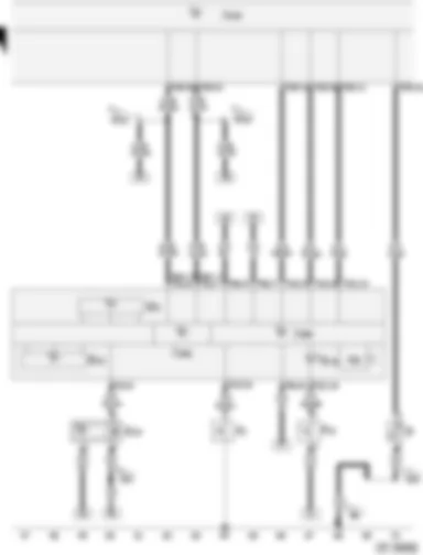
Wiring Diagram VW CITI GOLF 2005 - Oil pressure switch - Cold start warning system contact - Fuel gauge sender - Rev. Counter - Speedometer
| F1 | Oil pressure switch |
| F12 | Cold start warning system contact |
| G | Fuel gauge sender |
| G5 | Rev. Counter |
| G21 | Speedometer |
| G22 | Speedometer sender (Hall sender on gearbox) |
| H3 | Buzzer/gong |
| J285 | Control unit with display in dash panel insert |
| J519 | Onboard power supply control unit |
| J533 | Data bus diagnostic interface |
| K15 | Starting device warning lamp |
| T8b | 8-Pin Connector, black, on instrument panel insert |
| T28 | 28-Pin Connector, black |
| T32 | 32-Pin Connector, green, on instrument panel |
| 50 | Earth point, on left luggage compartment |
| 120 | Earth connection -2-, in headlight wiring harness |
| 218 | Earth connection -1-, in rear lid wiring harness |
| A121 | Connection (high bus), in dash panel wiring harness |
| A122 | Connection (low bus), in dash panel wiring harness |
Can't find your car? Check -> DiagnostData.com!


