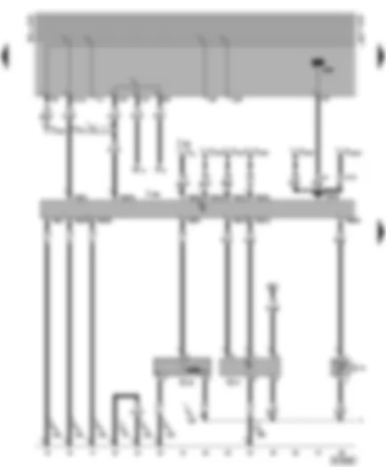
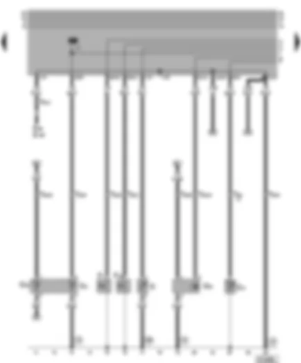
Wiring Diagram VW GOLF 1999 - Alternator - starter


| A | Battery |
| B | Starter |
| C | Alternator |
| C1 | Voltage regulator |
| D | Ignition/starter switch |
| F18 | Radiator fan thermo-switch |
| T2 | 2-pin connector, behind the relay plate |
| T2a | 2-pin connector, near battery |
| V7 | Radiator fan |
| 12 | Earth point, in engine compartment, left |
| 119 | Earth connection -1-, in headlight wiring harness |
| 156 | Earth connection, in Diesel direct injection system wiring harness |
| * | For manual gearbox only |
| For automatic gearbox only |
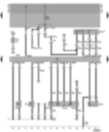
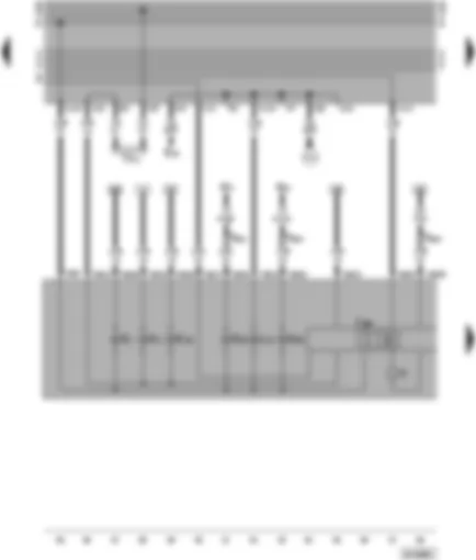
Wiring Diagram VW GOLF 1999 - Diesel direct injection system control unit - engine speed sender - air mass meter
| F | Brake light switch |
| G28 | Engine speed sender |
| G70 | Air mass meter, in engine compartment, front right |
| G72 | Intake manifold temperature sender |
| J248 | Diesel direct injection system control unit, in plenum chamber, centre |
| J362 | Immobilizer control unit |
| M9 | Brake light bulb, left |
| T1y | Single connector, behind relay plate |
| T10 | 10-pin connector, behind relay plate |
| T12a | 12-pin connector, behind relay plate |
| T68 | 68-pin connector |
| TV11 | Terminal 54 junction box, above the relay plate |
| 12 | Earth point, in engine compartment, left |
| 156 | Earth connection, in diesel direct injection wiring harness |
| 220 | Earth connection (sender earth), in engine wiring harness |
| * | Only models with air conditioner |
| ** | Only Climatronic |
| Only models with automatic gearbox |
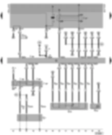
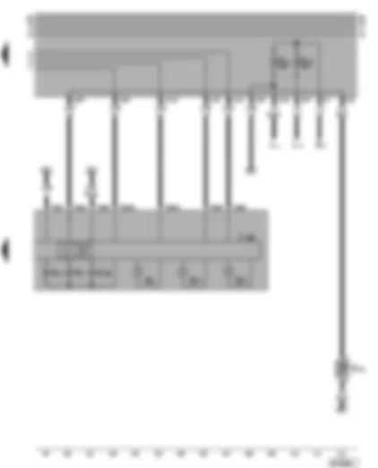
Wiring Diagram VW GOLF 1999 - Diesel direct injection system control unit - needle lift sender - modulating piston movement sender
| E45 | Cruise control system switch |
| F4 | Reversing light switch |
| F36 | Clutch pedal switch |
| F47 | Cruise control system brake pedal switch/diesel direct inj. system |
| G80 | Needle lift sender |
| G81 | Fuel temperature sender |
| G149 | Modulating piston movement sender |
| J217 | Automatic gearbox control unit |
| J248 | Diesel direct injection system control unit, in plenum chamber, centre |
| N146 | Metering adjuster |
| T1 | Single connector, behind relay plate |
| T4a | 4-pin connector, behind steering column switch trim |
| T4b | 4-pin connector, next to steering column |
| T8 | 8-pin connector |
| T10 | 10-pin connector, behind relay plate |
| T24 | 24-pin connector, on engine |
| T68 | 68-pin connector |
| TV5 | Terminal 15a junction box |
| 156 | Earth connection, in diesel direct injection wiring harness |
| 220 | Earth connection (sender earth), in engine wiring harness |
| * | Only models with cruise control system (CCS) |
| ** | Only models with manual gearbox |
| Only models with automatic gearbox |
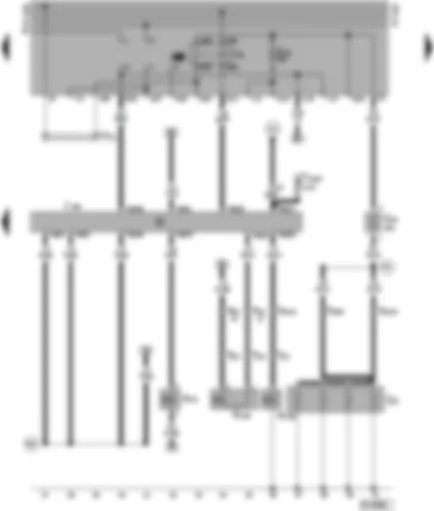
Wiring Diagram VW GOLF 1999 - Diesel direct injection system control unit - accelerator position sender - coolant heater elements
| A | Battery |
| G79 | Accelerator position sender |
| J248 | Diesel direct injection system control unit, centre in plenum chamber |
| J317 | Terminal 30 voltage supply relay |
| J325 | Coolant heater element relay, centre on bulkhead |
| J359 | Low heat output relay |
| J360 | High heat output relay |
| N18 | Exhaust gas recirculation valve, front right in engine compartment |
| Q7 | Coolant heating elements |
| S109 | Coolant heater element fuse |
| T6 | 6-pin connector, front left in footwell compartment |
| T24 | 24-pin connector, on engine |
| T68 | 68-pin connector |
| TV13 | Speed signal junction box |
| 156 | Earth connection, in diesel direct injection system wiring harness |
| F25 | Connection -1-, in diesel direct injection system wiring harness |
| F32 | Connection (glow plugs - coolant), in diesel direct injection system wiring harness |
| * | For manual gearbox only |
| For automatic gearbox only |
Wiring Diagram VW GOLF 1999 - Diesel direct injection system control unit - fuel cut-off valve - engine glow plugs
| J52 | Glow plug relay |
| J248 | Diesel direct injection system control unit, centre in plenum chamber |
| N75 | Charge pressure control solenoid valve |
| N108 | Commencement of injection valve |
| N109 | Fuel shut-off valve |
| Q6 | Glow plugs - (engine) |
| S39 | Glow plugs fuse, above the relay plate |
| T3 | 3-pin connector, in centre of engine compartment |
| T12a | 12-pin connector, behind the relay plate |
| T24 | 24-pin connector, on engine |
| T68 | 68-pin connector |
| TV2 | Terminal 30 junction box, above the relay plate |
| F26 | Connection -2-, in diesel direct injection system wiring harness |
| F31 | Connection (glow plugs - engine), in diesel direct injection system wiring harness |
| L41 | Connection (air conditioer on), in air conditioer/radiator fan wiring harness |
| * | For air conditioning system only |
| ** | For Climatronic only |
Wiring Diagram VW GOLF 1999 - Engine temperature sender - oil pressure switch - speedometer sender
| E86 | Multi-function display call-up button |
| E109 | Multi-function display, memory switch |
| F1 | Oil pressure switch |
| F22 | Oil pressure switch (0.3 bar) |
| G | Fuel gauge sender |
| G2 | Coolant temperature sender |
| G8 | Oil temperature sender |
| G22 | Speedometer sender |
| G62 | Coolant temperature sender |
| T4c | 4-pin connector, behind steering column switch trim |
| T24 | 24-pin connector, on engine |
| 18 | Earth point, on engine block |
| 196 | Earth connection -1-, in rear wiring harness |
Wiring Diagram VW GOLF 1999 - Dash panel insert - warning lamps
| E20 | Switches and instruments - lighting control |
| J285 | Control unit with display in dash panel insert |
| K1 | Main beam warning lamp |
| K2 | Alternator warning lamp |
| K29 | Glow period warning lamp |
| K65 | Left turn signal warning lamp |
| K94 | Right turn signal warning lamp |
| L10 | Dash panel insert light bulb |
| M5 | Turn signal bulb, front left |
| M7 | Turn signal bulb, front right |
| T3b | 3-pin connector, behind relay plate |
| T28 | 28-pin connector |
| TV4 | Terminal 15 junction box |
| Y | Analogue clock |
| A11 | Positive (+) connection (58b), in wiring harness for instruments |
Wiring Diagram VW GOLF 1999 - Dash panel insert - fuel gauge - coolant temperature gauge - rev. counter
| E4 | Headlight dipper/flasher switch |
| G1 | Fuel gauge |
| G3 | Coolant temperature gauge |
| G5 | Rev. counter |
| G32 | Coolant shortage indicator sender |
| J285 | Control unit with display in dash panel insert |
| K3 | Oil pressure warning lamp |
| K7 | Dual circuit brake/handbrake warning lamp |
| K28 | Coolant temperature/coolant shortage warning lamp |
| L1 | Twin filament bulb/sealed beam insert, left |
| L2 | Twin filament bulb/sealed beam insert, right |
| T28 | 28-pin connector, in dash panel insert |
Не нашел автомобиль произведенный после 2014 года? смотри здесь -> DiagnostData.com!


 English
