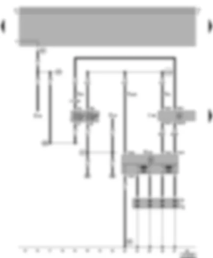
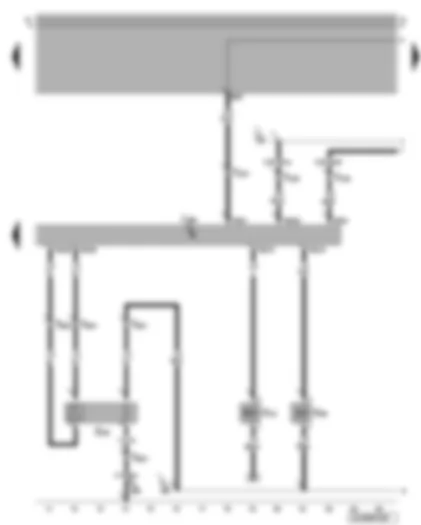
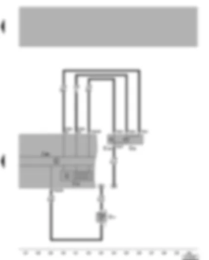
Wiring Diagram VW GOLF 1999 - Alternator - starter


| A | Battery |
| B | Starter |
| C | Alternator |
| C1 | Voltage regulator |
| D | Ignition/starter switch |
| J59 | X-contact relief relay |
| S163 | Fuse 2 (30), on battery fuse holder |
| S176 | Fuse 4 (30), on battery fuse holder |
| S177 | Fuse 2 (30), on battery fuse holder |
| T2e | 2-pin connector, near starter (on vehicles with no air conditioning system) |
| T4 | 4-pin connector, near starter (on vehicles with an air conditioning system) |
| T6 | 6-pin connector, brown, in protective housing for connectors on left in plenum chamber |
| 81 | Earth connection 1, in dash panel wiring harness |
| 500 | Screw connection 1 (30), on relay plate |
| 502 | Screw connection (30a), on relay plate |
| A17 | Connection (61), in dash panel wiring harness |
| * | From May 1998 |
| -●●- | To April 1998 |
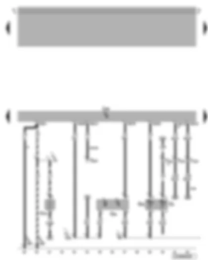
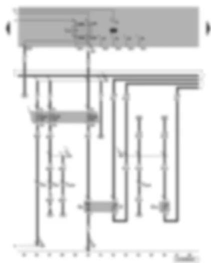
Wiring Diagram VW GOLF 1999 - 4AV injection system control unit - ignition system
| D | Ignition/starter switch |
| J448 | 4AV injection system control unit, centre in plenum chamber |
| N152 | Ignition transformer |
| P | Spark plug connector |
| Q | Spark plug |
| S10 | Fuse 10 in fuse holder |
| S229 | Fuse 29 in fuse holder |
| T4a | 4-pin connector |
| T6 | 6-pin connector, brown, in protective housing for connectors on left in plenum chamber |
| T10a | 10-pin connector, in cable channel on left in engine compartment |
| T80 | 80-pin connector |
| 85 | Earth connection 1, in engine compartment wiring harness |
| 501 | Screw connection 2 (30), on relay plate |
| A2 | Positive connection (15), in dash panel wiring harness |
| A32 | Positive connection (30), in dash panel wiring harness |
| A98 | Positive connection 4 (30), in dash panel wiring harness |
| A104 | Positive connection 2 (15), in dash panel wiring harness |
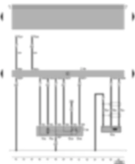
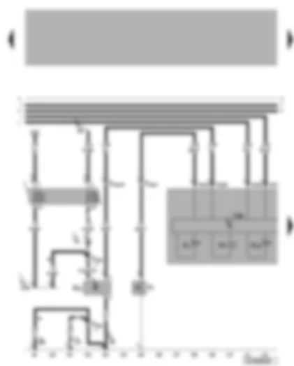
Wiring Diagram VW GOLF 1999 - 4CV injection system control unit - crankcase breather heater element - coolant temperature sender - Hall sender
| G2 | Coolant temperature sender |
| G40 | Hall sender |
| G62 | Coolant temperature sender |
| J448 | 4AV injection system control unit, centre in plenum chamber |
| N79 | Crankcase breather heater element |
| T10 | 10-pin connector, orange, in protective housing for connectors on left in plenum chamber |
| T10a | 10-pin connector, in cable channel on left in engine compartment |
| T80 | 80-pin connector |
| 131 | Earth connection 2, in engine compartment wiring harness |
| 220 | Earth connection (sender earth), in engine wiring harness |
| 608 | Earth point, centre in plenum chamber |
| D101 | Connection 1, in engine wiring harness |
| ** | Fuel consumption display signal from engine control unit, only MFI |
| *** | Radiator fan control unit connection |
| # | Only models with no crankcase breather heater element |
| -●- | Only models with crankcase breather heater element |
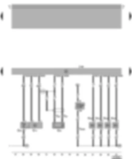
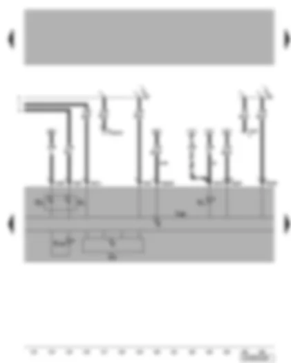
Wiring Diagram VW GOLF 1999 - 4CV injection system control unit - throttle valve module - engine speed sender
| F60 | Idling speed switch |
| G28 | Engine speed sender |
| G69 | Throttle valve potentiometer |
| G88 | Throttle valve module potentiometer |
| J226 | Starter inhibitor and reversing light relay, above central electrics |
| J338 | Throttle valve module |
| J448 | 4AV injection system control unit, centre in plenum chamber |
| T3 | 3-pin connector, near intake manifold |
| T8 | 8-pin connector |
| T10 | 10-pin connector, orange, in protective housing for connectors on left in plenum chamber |
| T80 | 80-pin connector |
| V60 | Throttle valve module |
| ** | Connection air conditioning system |
| --- | Only models with automatic gearbox |
Wiring Diagram VW GOLF 1999 - 4AV injection system control unit - intake manifold pressure sender - intake manifold temperature sender - knock sensor - injectors
| G42 | Intake air temperature sender |
| G61 | Knock sensor |
| G71 | Intake manifold pressure sender |
| J448 | 4AV injection system control unit, centre in plenum chamber |
| N30 | Injector, cylinder 1 |
| N31 | Injector, cylinder 2 |
| N32 | Injector, cylinder 3 |
| N33 | Injector, cylinder 4 |
| S232 | Fuse 32 in fuse holder |
| T2 | 2-pin connector, on left of cylinder head |
| T10a | 10-pin connector, in cable channel on left in engine compartment |
| T80 | 80-pin connector |
| 220 | Earth connection (sender earth), in engine wiring harness |
| D95 | Connection (injectors), in engine compartment wiring harness |
| D102 | Connection 2, in engine compartment wiring harness |
Wiring Diagram VW GOLF 1999 - 4AV injection system control unit - Lambda probe - activated charcoal filter system solenoid valve - exhaust gas recirculation valve
| G39 | Lambda probe |
| J448 | 4AV injection system control unit, centre in plenum chamber |
| N18 | Exhaust gas recirculation valve |
| N80 | Activated charcoal filter system solenoid valve 1 |
| T4b | 4-pin connector, near Lambda probe |
| T10 | 10-pin connector, orange, in protective housing for connectors on left in plenum chamber |
| T80 | 80-pin connector |
| 609 | Earth point, on right in plenum chamber |
| A27 | Connection (speed signal), in dash panel wiring harness |
| E30 | Connection (87a), in engine wiring harness |
Wiring Diagram VW GOLF 1999 - Fuel pump - fuel gauge sender - coolant shortage indicator sender
| G | Fuel gauge sender |
| G6 | Fuel pump |
| G32 | Coolant shortage indicator sender |
| J17 | Fuel pump relay |
| S228 | Fuse 28 in fuse holder |
| S234 | Fuse 34 in fuse holder |
| S243 | Fuse 43 in fuse holder |
| T6 | 6-pin connector, brown, in protective housing for connectors on left in plenum chamber |
| T10a | 10-pin connector, in cable channel on left in engine compartment |
| 135 | Earth connection 2, in dash panel wiring harness |
| 269 | Earth connection (sender earth) 1, in dash panel wiring harness |
| 504 | Screw connection (87F), on relay plate |
| A99 | Connection 1 (87), in dash panel wiring harness |
| A100 | Connection 2 (87), in dash panel wiring harness |
| E30 | Connection (87a), in engine wiring harness |
| -●- | Only models with crankcase breather heater element |
Wiring Diagram VW GOLF 1999 - Dash panel insert - optical and acoustic oil pressure warning - speedometer sender - coolant temperature/coolant shortage indicator
| F1 | Oil pressure switch |
| G22 | Speedometer sender (Hall sender on gearbox) |
| H3 | Warning buzzer |
| J285 | Control unit with display in dash panel insert |
| K3 | Oil pressure warning lamp |
| K28 | Coolant temperature/coolant shortage warning lamp |
| S2 | Fuse 2 in fuse holder |
| S7 | Fuse 7 in fuse holder |
| T10a | 10-pin connector, in cable channel on left in engine compartment |
| T32 | 32-pin connector, blue |
| 85 | Earth connection 1, in engine compartment wiring harness |
| 179 | Earth connection, in left headlight wiring harness |
| 503 | Screw connection (75x), on relay plate |
| 608 | Earth point, centre in plenum chamber |
| A1 | Positive connection (30a), in dash panel wiring harness |
| B163 | Positive connection 1 (15), in interior wiring harness |
| * | From May 1998 |
| -●●- | To April 1998 |
Wiring Diagram VW GOLF 1999 - Dash panel insert - coolant temperature gauge - fuel gauge - rev. counter - self-diagnosis connection
| G1 | Fuel gauge |
| G3 | Coolant temperature gauge |
| G5 | Rev. counter |
| J285 | Control unit with display in dash panel insert |
| K2 | Alternator warning lamp |
| K105 | Reserve fuel warning lamp |
| T12a | 12-pin connector, connector only on models with Climatronic |
| T16 | 16-pin connector, centre in dash panel, self-diagnosis connection |
| T32 | 32-pin connector, blue |
| T32a | 32-pin connector, green |
| A27 | Connection (speed signal), in dash panel wiring harness |
| A76 | Connection (K-diagnosis wire), in dash panel wiring harness |
| * | From May 1998 |
| -●●- | To April 1998 |
| ** | Fuel consumption display signal from engine control unit, only MFI |
Wiring Diagram VW GOLF 1999 - Dash panel insert - multifunction display - ambient temperature indicator
| E86 | Multifunction display call-up button |
| E109 | Multifunction display memory switch |
| G17 | Ambient temperature sensor |
| J119 | Multifunction display |
| J285 | Control unit with display in dash panel insert |
| T6e | 6-pin connector |
| T32a | 32-pin connector, green |
Can't find your car? Check -> DiagnostData.com!


 Русский
