Wiring Diagram VW GOLF 1999 - 'Digital sound package' amplifier - program selection operating unit

| E20 | Switch and instrument illumination regulator |
| E200 | Program selection operating unit |
| J285 | Control unit with display in dash panel insert |
| L45 | Memory operating unit illumination bulb |
| R12 | Amplifier, on left in luggage compartment |
| T6c | 6-pin connector |
| T16 | 16-pin connector, centre in dash panel, self-diagnosis connection |
| T20b | 20-pin connector |
| T23 | 23-pin connector |
| T24 | 24-pin connector |
| T32 | 32-pin connector, blue |
| 45 | Earth point, centre behind dash panel |
| 256 | Earth connection 2, in radio wiring harness |
| A4 | Positive connection (58b), in dash panel wiring harness |
| A27 | Connection (speed signal), in dash panel wiring harness |
| A76 | Connection (K-diagnosis wire), in dash panel wiring harness |
| * | From May 1999 |
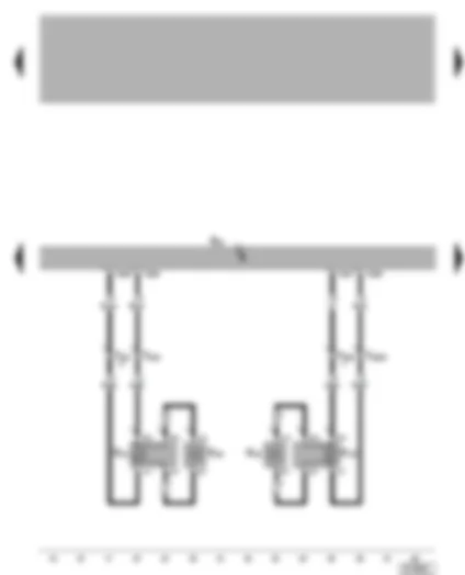
Wiring Diagram VW GOLF 1999 - 'Digital sound package' amplifier - front loudspeakers
| R12 | Amplifier, on left in luggage compartment |
| R20 | Front left treble loudspeaker in door |
| R21 | Front left bass loudspeaker in door |
| R22 | Front right treble loudspeaker, in door |
| R23 | Front right bass loudspeaker, in door |
| T10i | 10-pin connector, black, left A-pillar coupling station |
| T10k | 10-pin connector, black, right A-pillar coupling station |
| T23 | 23-pin connector |
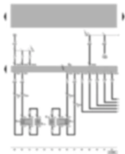
Wiring Diagram VW GOLF 1999 - 'Digital sound package' amplifier - rear loudspeakers
| J412 | Mobile telephone operating electronics control unit, next to handbrake lever |
| R12 | Amplifier, on left in luggage compartment |
| R14 | Rear left treble loudspeaker, in door |
| R15 | Rear left bass loudspeaker, in door |
| R16 | Rear right treble loudspeaker, in door |
| R17 | Rear right bass loudspeaker, in door |
| T10l | 10-pin connector, black, left B-pillar coupling station |
| T10m | 10-pin connector, black, right B-pillar coupling station |
| T18a | 18-pin connector |
| T23 | 23-pin connector |
| T24 | 24-pin connector |
| V21 | Positive connection (30), in radio - amplifier wiring harness |
| V38 | Connection (mute circuit), in DSP/telephone wiring harness |
Wiring Diagram VW GOLF 1999 - Radio - CD changer
| R | Radio |
| R41 | CD changer |
| T8 | 8-pin connector |
| T12 | 12-pin connector |
| T20 | 20-pin connector |
| 45 | Earth point, centre behind dash panel |
| 255 | Earth connection 1, in radio wiring harness |
| V14 | Connection (screening), in CD changer wiring harness |
| V38 | Connection (mute circuit), in DSP/telephone wiring harness |
Wiring Diagram VW GOLF 1999 - Radio - aerial
| D | Ignition/starter switch |
| J285 | Control unit with display in dash panel insert |
| R | Radio |
| R11 | Aerial |
| R24 | Aerial amplifier |
| S12 | Fuse 12 in fuse holder |
| S237 | Fuse 37 in fuse holder |
| S242 | Fuse 42 in fuse holder |
| T8 | 8-pin connector |
| T32 | 32-pin connector, blue |
| T32a | 32-pin connector, green |
| 255 | Earth connection 1, in radio wiring harness |
| 501 | Screw connection 2 (30), on relay plate |
| A21 | Connection (86s), in dash panel wiring harness |
| A23 | Connection (30a), in dash panel wiring harness |
| B111 | Positive connection 1 (30a), in interior wiring harness |
| * | From May 1999 |
| ** | To April 1999 |
Can't find your car? Check -> DiagnostData.com!