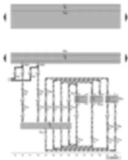
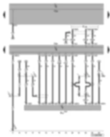
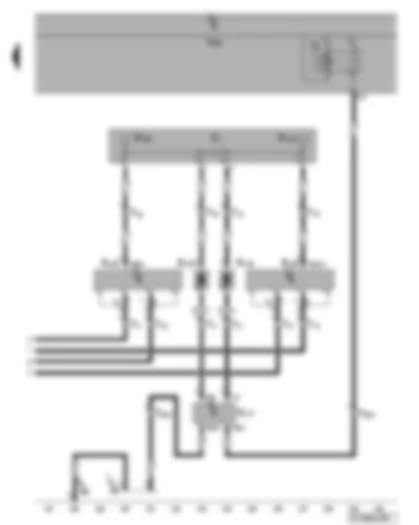
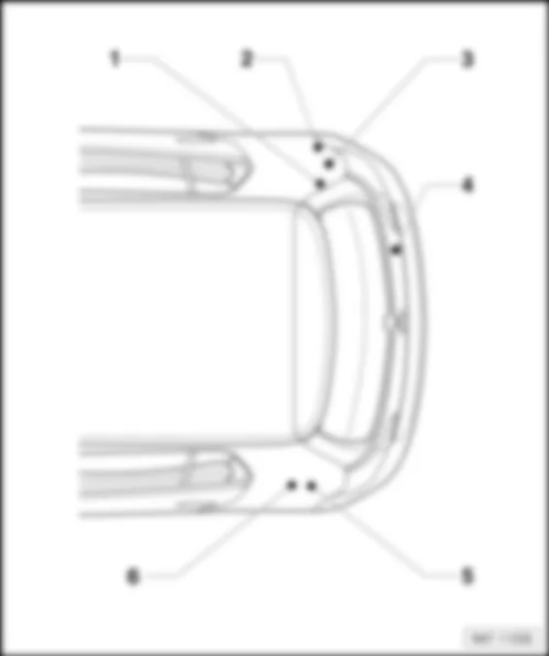
Wiring Diagram VW GOLF 2007 - Control unit with display for radio and navigation system - fuses - front left loudspeaker

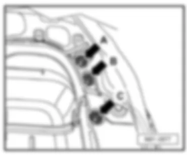
| A | Battery |
| B | Starter |
| C | Alternator |
| J503 | Control unit with display for radio and navigation |
| J519 | Onboard supply control unit |
| R20 | Front left treble loudspeaker |
| R21 | Front left bass loudspeaker |
| SA1 | Fuse 1 on fuse holder A |
| SB8 | Fuse 8 on fuse holder B |
| SB19 | Fuse 19 on fuse holder B, E-box high |
| T16b | 16-pin connector |
| T28 | 28-pin connector, coupling point, left A-pillar |
| T40 | 40-pin connector |
| 508 | Screw connection (30) on E-box |
| B224 | Connection 1 (radio), in interior wiring harness |
| * | Models with 90 A/120 A alternator |
| ** | Models with 140 A alternator |
| ### | Only models with 8 loudspeakers |
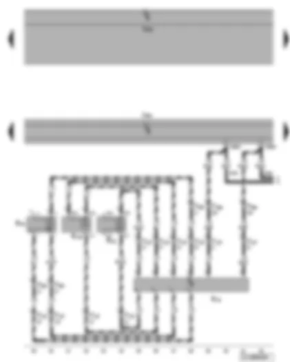
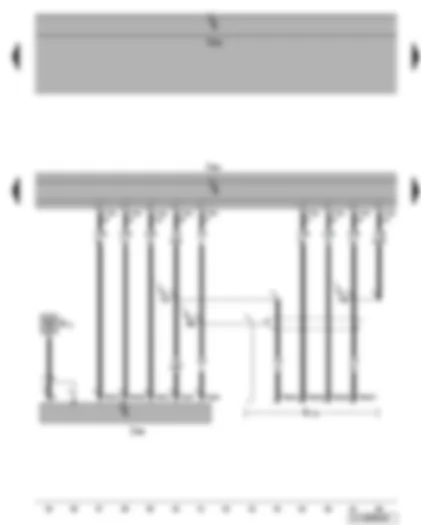
Wiring Diagram VW GOLF 2007 - Front left loudspeaker - left frequency switch
| J519 | Onboard supply control unit |
| R18 | Left frequency switch, in driver door |
| R20 | Front left treble loudspeaker |
| R21 | Front left bass loudspeaker |
| R103 | Front left mid-range loudspeaker |
| T4be | 4-pin connector, in driver door |
| T12e | 12-pin connector, in driver door |
| T16b | 16-pin connector |
| T28 | 28-pin connector, coupling point, left A-pillar |
| ### | Only models with 8 loudspeakers |
| -●●- | Only models with 10 loudspeakers |
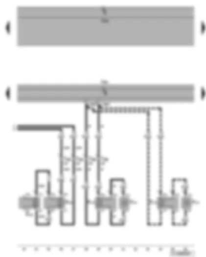
Wiring Diagram VW GOLF 2007 - Front right loudspeaker - right frequency switch
| J519 | Onboard supply control unit |
| R19 | Right frequency switch, in front passenger door |
| R22 | Front right treble loudspeaker |
| R23 | Front right bass loudspeaker |
| R104 | Front right mid-range loudspeaker |
| T4bf | 4-pin connector, in front passenger door |
| T12f | 12-pin connector, in front passenger door |
| T16b | 16-pin connector |
| T28a | 28-pin connector, coupling point, right A-pillar |
| ### | Only models with 8 loudspeakers |
| -●●- | Only models with 10 loudspeakers |
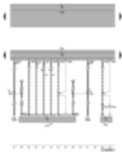
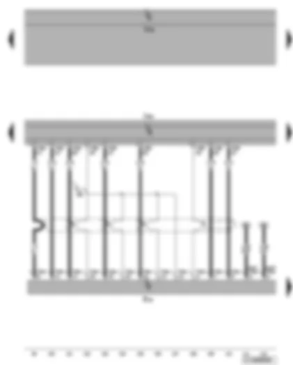
Wiring Diagram VW GOLF 2007 - Control unit with display for radio and navigation - front right loudspeaker - rear left loudspeaker
| J503 | Control unit with display for radio and navigation |
| J519 | Onboard supply control unit |
| R14 | Rear left treble loudspeaker |
| R15 | Rear left bass loudspeaker |
| R22 | Front right treble loudspeaker |
| R23 | Front right bass loudspeaker |
| T16b | 16-pin connector |
| T28a | 28-pin connector, coupling point, right A-pillar |
| T28b | 28-pin connector, left B-pillar coupling point |
| * | Only 4-door model |
| --- | Only 2-door model |
| ### | Only models with 8 loudspeakers |
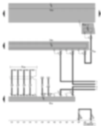
Wiring Diagram VW GOLF 2007 - Control unit with display for radio navigation system - mobile telephone operating electronics control unit
| J412 | Mobile telephone operating electronics control unit |
| J503 | Control unit with display for radio and navigation |
| J519 | Onboard supply control unit |
| J533 | Data bus diagnostic interface |
| R38 | Telephone microphone |
| T2f | 2-pin connector, near front interior light |
| T12g | 12-pin connector |
| T16b | 16-pin connector |
| T20 | 20-pin connector |
| T54 | 54-pin connector |
| A178 | Connection (infotainment CAN bus, high), in dash panel wiring harness |
| A179 | Connection (infotainment CAN bus, low), in dash panel wiring harness |
| ** | Component is not part of preparation |
| -●- | Only models with mobile telephone/preparation for mobile telephone |
| xxx | From May 2008 |
Wiring Diagram VW GOLF 2007 - Control unit with display for radio and navigation - CD changer - connection for external audio source
| J519 | Onboard supply control unit |
| J503 | Control unit with display for radio and navigation |
| R41 | CD changer |
| R199 | Connection for external audio sources |
| T3aq | 3-pin connector, in glove compartment |
| T12 | 12-pin connector |
| T12d | 12-pin connector |
| T16b | 16-pin connector |
| 370 | Earth connection 5, in main wiring harness |
| 371 | Earth connection 6, in main wiring harness |
| B340 | Connection 1 (58d), in main wiring harness |
| V14 | Connection (screening), in CD changer wiring harness |
| V45 | Connection 2 (screening), in CD changer wiring harness |
| * | Only models with CD changer/preparation for CD changer |
| ## | Only with external audio connection in glove compartment |
| ** | Component is not part of preparation |
Wiring Diagram VW GOLF 2007 - Control unit with display for radio navigation system - traffic information control unit
| J503 | Control unit with display for radio and navigation |
| J519 | Onboard supply control unit |
| J559 | Traffic information control unit |
| R11 | Aerial |
| R173 | Traffic data aerial |
| T2o | 2-pin connector |
| T6an | 6-pin connector |
| T8m | 8-pin connector |
| T12u | 12-pin connector |
| 489 | Earth connection (screening 1), in radio navigation system wiring harness |
| V67 | Positive connection 1, in radio navigation system wiring harness |
| V68 | Positive connection 2, in radio navigation system wiring harness |
Wiring Diagram VW GOLF 2007 - Control unit with display for radio and navigation system - TV tuner
| J503 | Control unit with display for radio and navigation |
| J519 | Onboard supply control unit |
| R78 | TV tuner, in front right footwell |
| T26d | 26-pin connector |
| T54a | 54-pin connector |
| 490 | Earth connection (screening 2), in radio navigation system wiring harness |
Wiring Diagram VW GOLF 2007 - Control unit with display for radio and navigation - navigation system aerial - TV tuner - connection for TV card reader
| J503 | Control unit with display for radio and navigation |
| J519 | Onboard supply control unit |
| R50 | Navigation system aerial |
| R78 | TV tuner, in front right footwell |
| R204 | TV card reader |
| T2ay | 2-pin connector, near roof aerial |
| T4bk | 4-pin connector |
| T4bl | 4-pin connector, in glove compartment |
| T54a | 54-pin connector |
Wiring Diagram VW GOLF 2007 - Rear window antenna - heated rear window - aerial module
| J9 | Heated rear window relay |
| J519 | Onboard supply control unit |
| R108 | Left aerial module |
| R109 | Right aerial module |
| R130 | Rear window aerial 1 |
| R131 | Rear window aerial 2 |
| R177 | Amplitude modulation (AM) frequency filter, in rear lid |
| R178 | Frequency modulation (FM) frequency filter in negative wire |
| R179 | Frequency modulation (FM) frequency filter in positive wire |
| T1a | Single pin connector, in rear lid |
| T1b | Single pin connector, in rear lid |
| T1c | Single connector |
| T1d | Single connector |
| T1g | Single pin connector, in rear lid |
| T1h | Single pin connector, in rear lid |
| T1i | Single pin connector, in rear lid |
| T1j | Single pin connector, in rear lid |
| T1q | Single pin connector, behind right C-pillar trim |
| T1r | Single pin connector, behind right C-pillar trim |
| T1s | Single pin connector, behind right C-pillar trim |
| T1t | Single pin connector, behind right C-pillar trim |
| T2b | 2-pin connector |
| T3al | 3-pin connector |
| T3am | 3-pin connector |
| T5a | 5-pin connector, black, in rear left side panel |
| T5e | 5-pin connector, pink, in rear left side panel |
| Z1 | Heated rear window |
| 369 | Earth connection 4, in main wiring harness |
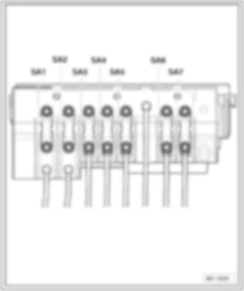
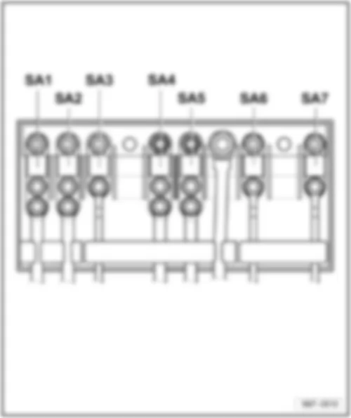
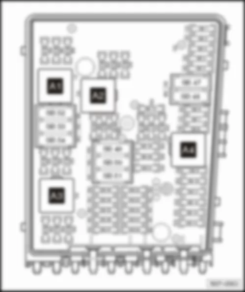
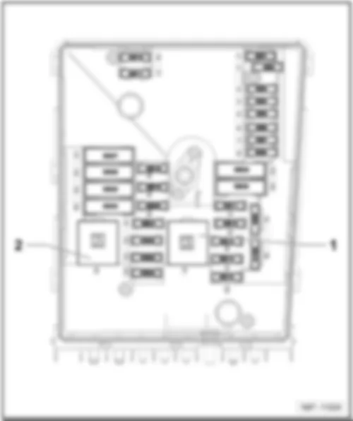
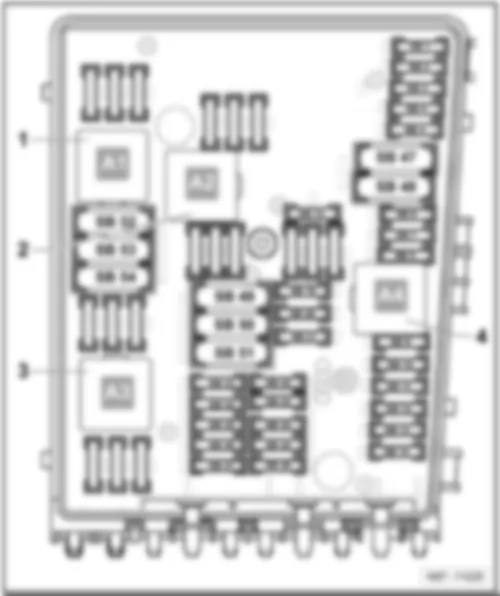
VW GOLF 2007 Overview of fuses (SA), (SB)
| Specified torques |
| ⇒ Electrical system, Repair Group 97, Removing and installing fuse holders |
| Fuse colours |
| 200 A - purple |
| 150 A - grey |
| 125 A - pink |
| 100 A - blue |
| 80 A - white |
| 70 A - brown |
| 60 A - yellow |
| 50 A - red |
| 40 A - green |
| 30 A - orange |
VW GOLF 2007 Fuse assignment for E-box low, from May 2005
| No. | Current Flow Diagram designation | Nominal value | Function/component | Terminal | ||
| 1 | - | SA1 - Fuse 1 on fuse holder A | 150A 200A | - | C - Alternator (90A/120A) C - Alternator (140A) | 30a |
| 2 | - | SA2 - Fuse 2 on fuse holder A | 80A | - | J500 - Power steering control unit V187 - Electromechanical power steering motor | 30a |
| 3 | - | SA3 - Fuse 3 on fuse holder A | 50A | - | J293 - Radiator fan control unit V7 - Radiator fan V177 - Radiator fan 2 | 30a |
| 4 | - | SA4 - Fuse 4 on fuse holder A | 40A | - | Special equipment | 30a |
| 5 | - | SA5 - Fuse 5 on fuse holder A | 100A 100A | - - | Fuses on fuse holder C, on left under dash panel SC43-SC45, SC28, SC22, SC18, SC19, SC12, (to November 2005) J604 - Auxiliary air heater control unit (to November 2005) Z35 - Auxiliary air heater element (to November 2005) | 30a |
| 6 | - | SA6 - Fuse 6 on fuse holder A | 80A 100A | - - | Fuses on fuse holder C, on left under dash panel SC43-SC45, SC28, SC22, SC18, SC19, SC12 J604 - Auxiliary air heater control unit (from November 2005) Z35 - Auxiliary air heater element (from November 2005) - Optional equipment | 30a |
| 7 | - | SA7 - Fuse 7 on fuse holder A | 50A 40A 30A | - - - | - Trailer operation - Special equipment, disabled persons - Special equipment, criminal investigation department | 30a |
VW GOLF 2007 Fuse assignment for E-box low, from May 2006
| No. | Current Flow Diagram designation | Nominal value | Function/component | Terminal | ||
| 1 | - | SA1 - Fuse 1 on fuse holder A | 150A 200A | - | C - Alternator (90A/120A) C - Alternator (140A) | 30a |
| 2 | - | SA2 - Fuse 2 on fuse holder A | 80A | - | J500 - Power steering control unit V187 - Electromechanical power steering motor | 30a |
| 3 | - | SA3 - Fuse 3 on fuse holder A | 50A | - | J293 - Radiator fan control unit V7 - Radiator fan V177 - Radiator fan 2 (500 Watt) | 30a |
| 4 | - | SA4 - Fuse 4 on fuse holder A | 40A | - | J359 - Low heat output relay (1st stage), (from December 2006) Z35 - Auxiliary air heater element (from December 2006) | 30a |
| 5 | - | SA5 - Fuse 5 on fuse holder A | 100A 100A | - - | Fuses on fuse holder C, on left under dash panel SC43-SC45, SC28, SC22, SC15-SC20, SC 12, SC22-SC27, SC19, SC38, (from November 2005) -Optional equipment (from November 2005) | 30a |
| 6 | - | SA6 - Fuse 6 on fuse holder A | 100A 80A | - | J604 - Auxiliary air heater control unit (from November 2005) Z35 - Auxiliary air heater element (from November 2005) J360 - High heat output relay (1st and 3rd stages), (from December 2006) Z35 - Auxiliary air heater element (from November 2006) | 30a |
| 7 | - | SA7 - Fuse 7 on fuse holder A | 40A 30A | - - | - Special equipment, disabled persons - Special equipment, criminal investigation department | 30a |
VW GOLF 2007 Fuse assignment for E-box low, from May 2007
| No. | Current Flow Diagram designation | Nominal value | Function/component | Terminal | ||
| 1 | - | SA1 - Fuse 1 on fuse holder A | 150A 200A | - | C - Alternator (90A/120A) C - Alternator (140A) | 30a |
| 2 | - | SA2 - Fuse 2 on fuse holder A | 80A | - | J500 - Power steering control unit V187 - Electromechanical power steering motor | 30a |
| 3 | - | SA3 - Fuse 3 on fuse holder A | 50A | - | J293 - Radiator fan control unit V7 - Radiator fan V177 - Radiator fan 2 (500 Watt) | 30a |
| 4 | - | SA4 - Fuse 4 on fuse holder A | 40A | - | J359 - Low heat output relay (1st stage), (from December 2006) Z35 - Auxiliary air heater element (from December 2006) | 30a |
| 5 | - | SA5 - Fuse 5 on fuse holder A | 100A 100A | - - | Fuses on fuse holder C, on left under dash panel SC43-SC45, SC28, SC22, SC15-SC20, SC 12, SC22-SC27, SC19, SC38, (from November 2005) -Optional equipment (from November 2005) | 30a |
| 6 | - | SA6 - Fuse 6 on fuse holder A | 100A 80A | - | J604 - Control unit for auxiliary air heater (from November 2005) Z35 - Heater element for auxiliary air heater (from November 2005) J360 - Relay for high heater output (1st and 3rd stages) (from December 2006) | 30a |
| 7 | - | SA7 - Fuse 7 on fuse holder A | 40A 30A | - - | - Special equipment, disabled persons - Special equipment, criminal investigation department | 30a |
VW GOLF 2007 Fuses (SA) on fuse holder A, on E-box high
| Specified torques |
| ⇒ Electrical system, Repair Group 97, Removing and installing fuse holders |
| Fuse colours |
| 200 A - purple |
| 150 A - grey |
| 125 A - pink |
| 100 A - blue |
| 80 A - white |
| 70 A - brown |
| 60 A - yellow |
| 50 A - red |
| 40 A - green |
| 30 A - orange |
VW GOLF 2007 Fuse assignment for E-box low, to May 2005
| No. | Current Flow Diagram designation | Nominal value | Function/component | Terminal | ||
| 1 | - | SA1 - Fuse 1 on fuse holder A | 150A 200A | - | C - Alternator (90A/120A) C - Alternator (1401A) TV2 - Terminal 30 wiring junction (rear battery) | 30a |
| 2 | - | SA2 - Fuse 2 on fuse holder A | 80A | - | J500 - Power steering control unit V187 - Electromechanical power steering motor | 29a |
| 3 | - | SA3 - Fuse 3 on fuse holder A | 50A | - | J293 - Radiator fan control unit V7 - Radiator fan V177 - Radiator fan 2 (500 W) | 29a |
| 4 | - | SA4 - Fuse 4 on fuse holder A | - | - | - Not assigned | 29a |
| 5 | - | SA5 - Fuse 5 on fuse holder A | 50A 80A | - - | Fuses on fuse holder C, on left under dash panel SC12-SC17, SC19, SC22-SC27, SC32-SC38, SC43-SC45 | 30a |
| 6 | - | SA6 - Fuse 6 on fuse holder A | 125A | - | SF1 - Fuse 1 on fuse holder F (rear battery) | 30a |
| 7 | - | SA7 - Fuse 7 on fuse holder A | - | - | - Not assigned | 30a |
VW GOLF 2007 Fuse assignment for E-box high, from May 2005
| No. | Current Flow Diagram designation | Nominal value | Function/component | Terminal | ||
| 1 | - | SA1 - Fuse 1 on fuse holder A | 150A 200A | - | C - Alternator (90A/120A) C - Alternator (1401A) | 30a |
| 2 | - | SA2 - Fuse 2 on fuse holder A | 80A | - | J500 - Power steering control unit V187 - Electromechanical power steering motor | 30a |
| 3 | - | SA3 - Fuse 3 on fuse holder A | 50A | - | J293 - Radiator fan control unit V7 - Radiator fan V177 - Radiator fan 2 | 30a |
| 4 | - | SA4 - Fuse 4 on fuse holder A | 80A | - | Fuses on fuse holder C, on left under dash panel: SC32-SC 37, Driver seat adjustment thermal fuse 1 - 30A | 29a |
| 5 | - | SA5 - Fuse 5 on fuse holder A | 100A | - | J604 - Auxiliary air heater control unit Z35 - Auxiliary air heater element | 30a |
| 6 | - | SA6 - Fuse 6 on fuse holder A | 80A 100A | - - | Fuses on fuse holder C, on left under dash panel: SC18-SC20, SC22-SC28, SC43-SC45 optional equipment | 30a 30a |
| 7 | - | SA7 - Fuse 7 on fuse holder A | 50A | - | Fuses on fuse holder C, on left under dash panel: SC22-SC27 | 30a |
VW GOLF 2007 Fuse assignment for E-box high, from November 2005
| No. | Current Flow Diagram designation | Nominal value | Function/component | Terminal | ||
| 1 | - | SA1 - Fuse 1 on fuse holder A | 150A 200A | - | C - Alternator (90A/120A) C - Alternator (1401A) TV2 - Terminal 30 wiring junction (rear battery) | 30a |
| 2 | - | SA2 - Fuse 2 on fuse holder A | 80A | - | J500 - Power steering control unit V187 - Electromechanical power steering motor | 29a |
| 3 | - | SA3 - Fuse 3 on fuse holder A | 50A | - | J293 - Radiator fan control unit V7 - Radiator fan V177 - Radiator fan 2 (500 W) | 29a |
| 4 | - | SA4 - Fuse 4 on fuse holder A | - | - | - Not assigned | 29a |
| 5 | - | SA5 - Fuse 5 on fuse holder A | 50A | - | Fuses on fuse holder C, on left under dash panel SC12-SC17, SC19, SC22-SC27, SC32-SC38, SC43-SC45 | 30a |
| 6 | - | SA6 - Fuse 6 on fuse holder A | 125A | - | SF1 - Fuse 1 on fuse holder F (rear battery) | 30a |
| 7 | - | SA7 - Fuse 7 on fuse holder A | - | - | - Not assigned | 30a |
VW GOLF 2007 Fuse assignment for E-box high, from May 2007
| No. | Current Flow Diagram designation | Nominal value | Function/component | Terminal | ||
| 1 | - | SA1 - Fuse 1 on fuse holder A | 150A 200A | - | C - Alternator (90A/120A) C - Alternator (1401A) TV2 - Terminal 30 wiring junction (rear battery) | 30a |
| 2 | - | SA2 - Fuse 2 on fuse holder A | 80A | - | J500 - Power steering control unit V187 - Electromechanical power steering motor | 29a |
| 3 | - | SA3 - Fuse 3 on fuse holder A | 50A | - | J293 - Radiator fan control unit V7 - Radiator fan V177 - Radiator fan 2 (500 W) | 29a |
| 4 | - | SA4 - Fuse 4 on fuse holder A | - | - | - Not assigned | 29a |
| 5 | - | SA5 - Fuse 5 on fuse holder A | 50A 80A | - - | Fuses on fuse holder C, on left under dash panel SC12-SC17, SC19, SC22-SC27, SC32-SC38, SC43-SC45 | 30a |
| 6 | - | SA6 - Fuse 6 on fuse holder A | 125A | - | SF1 - Fuse 1 on fuse holder F (rear battery) | 30a |
| 7 | - | SA7 - Fuse 7 on fuse holder A | - | - | - Not assigned | 30a |
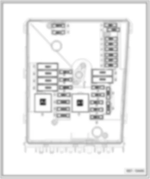
VW GOLF 2007 Fuses (SB) on E-box low, on left of engine compartment
| Fuse colours |
| 50 A - red |
| 40 A - orange |
| 30 A - light green |
| 25 A - natural (white) |
| 20 A - yellow |
| 15 A - light blue |
| 10 A - red |
| 7.5 A - brown |
| 5 A - light brown |
| 3 A - purple |
VW GOLF 2007 Fuse assignment for E-box low, from May 2005
| No. | Current Flow Diagram designation | Nominal value | Function/component | Terminal | ||
| F1 | - | SB1 - Fuse 1 on fuse holder B | 20A | - | J393 - Convenience system central control unit | 30a |
| F2 | - | SB2 - Fuse 2 on fuse holder B | 5A | - | J527 - Steering column electronics control unit | 30a |
| F3 | - | SB3 - Fuse 3 on fuse holder B | 5A | - | J519 - Onboard supply control unit | 30a |
| F4 | - | SB4 - Fuse 4 on fuse holder B | 30A | - | J104 - ABS control unit | 30a |
| F5 | - | SB5 - Fuse 5 on fuse holder B | 15A | - | J743 - Mechatronic control unit | 30a |
| F6 | - | SB6 - Fuse 6 on fuse holder B | 5A | - | J285 - Control unit in dash panel insert | 30a |
| F7 | - | SB7 - Fuse 7 on fuse holder B | 15A | - | J608 - Special vehicle control unit | 30a |
| F8 | - | SB8 - Fuse 8 on fuse holder B | 15A | - | J503 - Control unit with display for radio and navigation R - Radio | 30a |
| F9 | - | SB9 - Fuse 9 on fuse holder B | 5A | - | J412 - Mobile telephone operating electronics control unit | 30a |
| F10 | - | SB10 - Fuse 10 on fuse holder B | 5A 10A | - - | J317 - Terminal 30 voltage supply relay (models with petrol engine, not for engine codes BSE, BSF) J623 - Engine control unit (models with petrol engine, not for engine codes BSE, BSF) | 30a 30a |
| F11 | - | SB11 - Fuse 11 on fuse holder B | 20A | - | J364 - Auxiliary heater control unit | 30a |
| F12 | - | SB12 - Fuse 12 on fuse holder B | 5A | - | J533 - Data bus diagnostic interface | 30a |
| F13 | - | SB13 - Fuse 13 on fuse holder B | 30A 25A | - - | J623 - Engine control unit (only models with diesel engine) J623 - Petrol engine control unit (only models with petrol engine) | 87a |
| Golf | Fitting Locations | No. 802 / 15 |
| No. | Current Flow Diagram designation | Nominal value | Function/component | Terminal | ||
| F22 | - | SB22 - Fuse 22 on fuse holder B | 5A | - | F47 - Brake pedal switch (to November 2005) G476 - Clutch position sender | 87a |
| F23 | - | SB23 - Fuse 23 on fuse holder B | 5A 10A 15A | - - - | J299 - Secondary air pump relay (BSF) N18 - Exhaust gas recirculation valve N75 - Charge pressure control solenoid valve N345 - Exhaust gas recirculation cooler changeover valve N381 - Exhaust gas recirculation cooler changeover valve 2 N276 - Fuel pressure regulating valve | 87a |
| F24 | - | SB24 - Fuse 24 on fuse holder B | 10A | - | F265 - Map-controlled engine cooling system thermostat J293 - Radiator fan control unit N18 - Exhaust gas recirculation valve N80 - Activated charcoal filter solenoid valve 1 N156 - Variable intake manifold changeover valve N205 - Inlet camshaft control valve 1 N316 - Intake manifold flap valve V157 - Intake manifold flap motor | 87a |
| F25 | - | SB25 - Fuse 25 on fuse holder B | 40A | - | J519 - Onboard supply control unit | 30a |
| F26 | - | SB26 - Fuse 26 on fuse holder B | 40A | - | J519 - Onboard supply control unit | 30a |
| F27 | - | SB27 - Fuse 27 on fuse holder B | 50A | - | J179 - Automatic glow period control unit | 30a |
| F28 | - | SB28 - Fuse 28 on fuse holder B | 40A | - | J681 - Terminal 15 voltage supply relay 2 | 30a |
| F29 | - | SB29 - Fuse 29 on fuse holder B | 50A | - | S44 - Driver seat adjustment thermal fuse 1 SC - Fuses 32-37 on fuse holder C | 29a |
| F30 | - | SB30 - Fuse 30 on fuse holder B | - | - | - Not assigned | 30a |
VW GOLF 2007 Fuse assignment for E-box low, from May 2006
| No. | Current Flow Diagram designation | Nominal value | Function/component | Terminal | ||
| F1 | - | SB1 - Fuse 1 on fuse holder B | - | - | - Not assigned | 30a |
| F2 | - | SB2 - Fuse 2 on fuse holder B | 5A | - | J527 - Steering column electronics control unit | 30a |
| F3 | - | SB3 - Fuse 3 on fuse holder B | 5A | - | J519 - Onboard supply control unit (measuring wire), for front battery | 30a |
| F4 | - | SB4 - Fuse 4 on fuse holder B | 30A | - | J104 - ABS control unit | 30a |
| F5 | - | SB5 - Fuse 5 on fuse holder B | 30A | - | J743 - Mechatronic control unit J285 - Control unit in dash panel insert | 30a |
| F6 | - | SB6 - Fuse 6 on fuse holder B | 5A | - | J285 - Control unit in dash panel insert | 30a |
| F7 | - | SB7 - Fuse 7 on fuse holder B | 25A | - | J608 - Special vehicle control unit | 30a |
| F8 | - | SB8 - Fuse 8 on fuse holder B | 15A 15A 25A | - - - | J503 - Control unit with display for radio and navigation system R - Radio R - Preparation for radio and navigation system with TV (models for Japan) | 30a 30a |
| F9 | - | SB9 - Fuse 9 on fuse holder B | 5A | - | J412 - Mobile telephone operating electronics control unit | 30a |
| F10 | - | SB10 - Fuse 10 on fuse holder B | 5A 10A 5A | - - | J317 -Terminal 30 voltage supply relay J623 - Engine control unit J359 - Low heat output relay | 30a |
| F11 | - | SB11 - Fuse 11 on fuse holder B | 20A | - | J364 - Auxiliary heater control unit | 30a |
| F12 | - | SB12 - Fuse 12 on fuse holder B | 5A | - | J533 - Data bus diagnostic interface | 30a |
| F13 | SB13 - Fuse 13 on fuse holder B | 30A 25A | J623 - Engine control unit (diesel) J623 - Engine control unit (petrol) | 87a | ||
| F14 | SB14 - Fuse 14 on fuse holder B | 20A | N152 - Ignition transformer N70-N323 - Ignition coils with output stage | 87a |
| Golf | Fitting Locations | No. 802 / 18 |
| No. | Current Flow Diagram designation | Nominal value | Function/component | Terminal | ||
| F23 | - | SB23 - Fuse 23 on fuse holder B | 5A 15A 10A | - - - | J299 - Secondary air pump relay N218 - Secondary air inlet valve N18 - Exhaust gas recirculation valve N80 - Activated charcoal filter system solenoid valve 1 V144 - Fuel system diagnostic pump (BGQ,BGP) N345 - Exhaust gas recirculation cooler changeover valve N276 - Fuel pressure regulating valve J623 - Engine control unit N156 - Variable intake manifold changeover valve | 87a |
| F24 | - | SB24 - Fuse 24 on fuse holder B | 10A | - | F265 - Map-controlled engine cooling system thermostat J293 - Radiator fan control unit N18 - Exhaust gas recirculation valve N75 - Charge pressure control solenoid valve N205 - Inlet camshaft control valve 1 N316 - Intake manifold flap valve N381 - Exhaust gas recirculation cooler changeover valves 2 V157 - Intake manifold flap motor | 30a |
| F25 | - | SB25 - Fuse 25 on fuse holder B | 30A | - | J519 - Onboard supply control unit (A/1) | 30a |
| F26 | - | SB26 - Fuse 26 on fuse holder B | 30A | - | J519 - Onboard supply control unit (D/1) | 30a |
| F27 | - | SB27 - Fuse 27 on fuse holder B | 40A 50A | - | J299 - Secondary air pump relay J179 - Automatic glow period control unit | 30a |
| F28 | - | SB28 - Fuse 28 on fuse holder B | 40A | - | J681 - Terminal 15 voltage supply relay 2 | 30a |
| F29 | - | SB29 - Fuse 29 on fuse holder B | 50A | - | J496 - Additional coolant pump relay S44 - Seat adjustment thermal fuse 1 - SC33, SC34, SC37 | 30a |
| F30 | - | SB30 - Fuse 30 on fuse holder B | 50A | - | J59 - X-contact relief relay (SC7, SC8, SC28-SC35) | 30a |
VW GOLF 2007 Fuse assignment for E-box low, from May 2007
| No. | Current Flow Diagram designation | Nominal value | Function/component | Terminal | ||
| F1 | - | SB1 - Fuse 1 on fuse holder B | - | - | - Not assigned | 30a |
| F2 | - | SB2 - Fuse 2 on fuse holder B | 5A | - | J527 - Steering column electronics control unit | 30a |
| F3 | - | SB3 - Fuse 3 on fuse holder B | 5A | - | J519 - Onboard supply control unit (measuring wire), for front battery | 30a |
| F4 | - | SB4 - Fuse 4 on fuse holder B | 30A | - | J104 - ABS control unit | 30a |
| F5 | - | SB5 - Fuse 5 on fuse holder B | 15A | - | J743 - Mechatronic control unit | 30a |
| F6 | - | SB6 - Fuse 6 on fuse holder B | 5A | - | J285 - Control unit in dash panel insert | 30a |
| F7 | - | SB7 - Fuse 7 on fuse holder B | 25A 30A | - | J608 - Special vehicle control unit J743 - Mechatronics control unit (0AM) | 30a |
| F8 | - | SB8 - Fuse 8 on fuse holder B | 15A 15A 25A | - - - | J503 - Control unit with display for radio and navigation system R - Radio R - Preparation for radio and navigation system with TV (models for Japan) | 30a 30a |
| F9 | - | SB9 - Fuse 9 on fuse holder B | 5A | - | J412 - Mobile telephone operating electronics control unit | 30a |
| F10 | - | SB10 - Fuse 10 on fuse holder B | 5A 10A 5A | - - | J317 -Terminal 30 voltage supply relay J623 - Engine control unit J359 - Low heat output relay | 30a |
| F11 | - | SB11 - Fuse 11 on fuse holder B | 20A | - | J364 - Auxiliary heater control unit | 30a |
| F12 | - | SB12 - Fuse 12 on fuse holder B | 5A | - | J533 - Data bus diagnostic interface | 30a |
| F13 | - | SB13 - Fuse 13 on fuse holder B | 30A | J623 - Engine control unit (diesel) J623 - Engine control unit (petrol) | 87a | |
| F14 | - | SB14 - Fuse 14 on fuse holder B | 20A | N152 - Ignition transformer N70-N323 - Ignition coils with output stage | 87a |
| Golf | Fitting Locations | No. 802 / 21 |
| No. | Current Flow Diagram designation | Nominal value | Function/component | Terminal | ||
| F23 | - | SB23 - Fuse 23 on fuse holder B | 5A 15A 10A 15A | - - - - | J299 - Secondary air pump relay N218 - Secondary air inlet valve N18 - Exhaust gas recirculation valve N80 - Activated charcoal filter system solenoid valve 1 V144 - Fuel system diagnostic pump (BGQ,BGP) N345 - Exhaust gas recirculation cooler changeover valve N276 - Fuel pressure regulating valve J623 - Engine control unit N156 - Variable intake manifold changeover valve | 87a |
| F24 | - | SB24 - Fuse 24 on fuse holder B | 10A | - | F265 - Map-controlled engine cooling system thermostat J293 - Radiator fan control unit N18 - Exhaust gas recirculation valve N75 - Charge pressure control solenoid valve N205 - Inlet camshaft control valve 1 N316 - Intake manifold flap valve N381 - Exhaust gas recirculation cooler changeover valves 2 V157 - Intake manifold flap motor | 30a |
| F25 | - | SB25 - Fuse 25 on fuse holder B | 30A | - | J519 - Onboard supply control unit (A/1) | 30a |
| F26 | - | SB26 - Fuse 26 on fuse holder B | 30A | - | J519 - Onboard supply control unit (D/1) | 30a |
| F27 | - | SB27 - Fuse 27 on fuse holder B | 40A 50A | - | J299 - Secondary air pump relay J179 - Automatic glow period control unit | 30a |
| F28 | - | SB28 - Fuse 28 on fuse holder B | 40A | - | J681 - Terminal 15 voltage supply relay 2 | 30a |
| F29 | - | SB29 - Fuse 29 on fuse holder B | 50A | - | J496 - Additional coolant pump relay S44 - Seat adjustment thermal fuse 1 - SC33, SC34, SC37 | 30a |
| F30 | - | SB30 - Fuse 30 on fuse holder B | 50A 40A | - | J59 - Relief relay for X - contact (SC7, SC8, SC28 - SC35) J519 - Onboard supply control unit (I/1) | 30a |
VW GOLF 2007 Fuses (SB) on E-box high, on left of engine compartment
| Fuse colours |
| 50 A - red |
| 40 A - orange |
| 30 A - light green |
| 25 A - natural (white) |
| 20 A - yellow |
| 15 A - light blue |
| 10 A - red |
| 7.5 A - brown |
| 5 A - light brown |
| 3 A - purple |
VW GOLF 2007 Fuse assignment for E-box low, to May 2005
| No. | Current Flow Diagram designation | Nominal value | Function/component | Terminal | ||
| F1 | - | SB1 - Fuse 1 on fuse holder B | 30A | - | J104 - ABS with EDL control unit | 30a |
| F2 | - | SB2 - Fuse 2 on fuse holder B | 30A | - | J104 - ABS with EDL control unit | 30a |
| F3 | - | SB3 - Fuse 3 on fuse holder B | 20A | - | J393 - Convenience system central control unit | 30a |
| F4 | - | SB4 - Fuse 4 on fuse holder B | 5A | - | J519 - Onboard supply control unit | 30a |
| F5 | - | SB5 - Fuse 5 on fuse holder B | 20A | - | H2 - Treble tone horn H7 - Bass tone horn | 30a |
| F6 | - | SB6 - Fuse 6 on fuse holder B | 5A 20A 20A | - | N276 - Fuel pressure regulating valve N152 - Ignition transformer N... - Ignition coils 1-4 with output stage | 87a |
| F7 | - | SB7 - Fuse 7 on fuse holder B | 5A | - | F47 - Cruise control system brake pedal switch G476 - Clutch position sender | 87a |
| F8 | - | SB8 - Fuse 8 on fuse holder B | 10A | - | F265 - Map-controlled engine cooling system thermostat N205 - Inlet camshaft control valve 1 N80 - Activated charcoal filter solenoid valve 1 (pulsed) N18 - Exhaust gas recirculation valve N316 - Intake manifold flap air control valve V157 - Intake manifold flap motor N79 - Crankcase breather heater element N156 - Variable intake manifold changeover valve J293 - Radiator fan control unit | 87a |
| Golf | Fitting Locations | No. 802 / 25 |
| No. | Current Flow Diagram designation | Nominal value | Function/component | Terminal | ||
| F18 | - | SB18 - Fuse 18 on fuse holder B | 30A | - | J608 - Special vehicle control unit | 30a |
| F19 | - | SB19 - Fuse 19 on fuse holder B | 15A | - | R - Radio J503 - Control unit with display for radio and navigation system | 30a |
| F20 | - | SB20 - Fuse 20 on fuse holder B | 10A | - | J412 - Mobile telephone operating electronics control unit (telephone /preparation for telephone) | 30a |
| F21 | - | SB21 - Fuse 21 on fuse holder B | - | - | - Not assigned | - |
| F22 | - | SB22 - Fuse 22 on fuse holder B | - | - | - Not assigned | - |
| F23 | - | SB23 - Fuse 23 on fuse holder B | - | - | - Not assigned | 15a |
| F24 | - | SB24 - Fuse 24 on fuse holder B | 10A | - | J533 - Data bus diagnostic interface | 30a |
| F25 | - | SB25 - Fuse 25 on fuse holder B | - | - | - Not assigned | - |
| F26 | - | SB26 - Fuse 26 on fuse holder B | 10A 5A | - | J220 - Motronic control unit J248 - Diesel direct injection system control unit J317 - Terminal 30 voltage supply relay | 30a |
| F27 | - | SB27 - Fuse 27 on fuse holder B | 10A | - | N79 - Heater element for crankcase breather | 15a |
| F28 | - | SB28 - Fuse 28 on fuse holder B | 20A | - | J217 - Automatic gearbox control unit F125 - Multifunction switch | 15a |
| F29 | - | SB29 - Fuse 29 on fuse holder B | 20A | - | N... - Ignition coils 1-4 with output stage N... - Injectors cylinders 1-4 | 15a |
| Golf | Fitting Locations | No. 802 / 27 |
| No. | Current Flow Diagram designation | Nominal value | Function/component | Terminal | ||
| F44 | - | SB44 - Fuse 44 on fuse holder B | - | - | - Not assigned | - |
| F45 | - | SB45 - Fuse 45 on fuse holder B | - | - | - Not assigned | - |
| F46 | - | SB46 - Fuse 46 on fuse holder B | - | - | - Not assigned | - |
| F47 | - | SB47 - Fuse 47 on fuse holder B | 40A | - | J519 - Onboard supply control unit | 30a |
| F48 | - | SB48 - Fuse 48 on fuse holder B | 40A | - | J519 - Onboard supply control unit | 30a |
| F49 | - | SB49 - Fuse 49 on fuse holder B | - | - | - Not assigned | 30a |
| F50 | - | SB50 - Fuse 50 on fuse holder B | - | - | - Not assigned | 30a |
| F51 | - | SB51 - Fuse 51 on fuse holder B | 50A | - | Q10 - Glow plug 1 Q11 - Glow plug 2 Q12 - Glow plug 3 Q13 - Glow plug 4 | 30a |
| F52 | - | SB52 - Fuse 52 on fuse holder B | 50A | - | J519 - Onboard supply control unit SC40-SC42, SC46, SC47, SC49 | 30a |
| F53 | - | SB53 - Fuse 53 on fuse holder B | 50A | - | Safety cutout for seat adjustment | 30a |
| F54 | - | SB54 - Fuse 54 on fuse holder B | 50A | - | J293 - Radiator fan control unit | 30a |
VW GOLF 2007 Fuse assignment for E-box high, from May 2005
| No. | Current Flow Diagram designation | Nominal value | Function/component | Terminal | ||
| F1 | - | SB1 - Fuse 1 on fuse holder B | 30A | - | J104 - ABS control unit (pump) | 30a |
| F2 | - | SB2 - Fuse 2 on fuse holder B | 30A | - | J104 - ABS control unit (valves) | 30a |
| F3 | - | SB3 - Fuse 3 on fuse holder B | 20A | - | J393 - Convenience system central control unit V217 - Front passenger side wiper motor | 30a |
| F4 | - | SB4 - Fuse 4 on fuse holder B | 5A | - | J519 - Onboard supply control unit (measuring wire) | 30a |
| F5 | - | SB5 - Fuse 5 on fuse holder B | 15A | - | J519 - Onboard supply control unit (horn) | 30a |
| F6 | - | SB6 - Fuse 6 on fuse holder B | 15A | - | N276 - Fuel pressure regulating valve | 87a |
| F7 | - | SB7 - Fuse 7 on fuse holder B | 15A | - | - Not assigned | |
| F8 | - | SB8 - Fuse 8 on fuse holder B | - | - | - Not assigned | |
| F9 | - | SB9 - Fuse 9 on fuse holder B | 10A | - | N249 - Turbocharger air recirculation valve N80 - Activated charcoal filter solenoid valve 1 N75 - Charge pressure control solenoid valve | 87a |
| F10 | - | SB10 - Fuse 10 on fuse holder B | - | - | - Not assigned | |
| F11 | - | SB11 - Fuse 11 on fuse holder B | 10A | - | Z19 - Lambda probe heater | 87a |
| F12 | - | SB12 - Fuse 12 on fuse holder B | 10A | - | Z29 - Lambda probe 1 heater after catalytic converter | 87a |
| F13 | - | SB12 - Fuse 12 on fuse holder B | 15A | - | J743 - Mechatronic control unit | 30a |
| F14 | - | SB14 - Fuse 14 on fuse holder B | - | - | - Not assigned | |
| F15 | - | SB15 - Fuse 15 on fuse holder B | 10A | - | V50 - Coolant circulation pump | 30a |
| F16 | - | SB16 - Fuse 16 on fuse holder B | 5A | - | J104 - Steering column control unit | 30a |
| F17 | - | SB17 - Fuse 17 on fuse holder B | 5A | - | J285 - Control unit in dash panel insert | 30a |
| F18 | - | SB18 - Fuse 18 on fuse holder B | 30A | - | R12 - Amplifier | 30a |
| F19 | - | SB19 - Fuse 19 on fuse holder B | 15A | - | R - Radio | 30a |
| Golf | Fitting Locations | No. 802 / 30 |
| No. | Current Flow Diagram designation | Nominal value | Function/component | Terminal | ||
| F38 | - | SB38 - Fuse 38 on fuse holder B | 10A | - | J293 - Radiator fan control unit | 87a |
| F39 | - | SB39 - Fuse 39 on fuse holder B | 5A | - | F - Brake light switch (to November 2005) | 87a |
| F40 | - | SB40 - Fuse 40 on fuse holder B | 20A | - | N70 - Ignition coil 1 with output stage N127 - Ignition coil 2 with output stage N291 - Ignition coil 3 with output stage N292 - Ignition coil 4 with output stage | 87a |
| F41 | - | SB41 - Fuse 41 on fuse holder B | - | - | - Not assigned | |
| F42 | - | SB42 - Fuse 42 on fuse holder B | 5A | - | J271 - Motronic current supply relay (to November 2005) | 87a |
| F43 | - | SB43 - Fuse 43 on fuse holder B | 30A | - | N70 - Ignition coil 1 with output stage N127 - Ignition coil 2 with output stage N291 - Ignition coil 3 with output stage N292 - Ignition coil 4 with output stage N323 - Ignition coil 5 with output stage N324 - Ignition coil 6 with output stage | 87a |
| F44 | - | SB44 - Fuse 44 on fuse holder B | - | - | - Not assigned | - |
| F45 | - | SB45 - Fuse 45 on fuse holder B | - | - | - Not assigned | - |
| F46 | - | SB46 - Fuse 46 on fuse holder B | - | - | - Not assigned | - |
| F47 | - | SB47 - Fuse 47 on fuse holder B | 40A | - | J519 - Onboard supply control unit | 30a |
| F48 | - | SB48 - Fuse 48 on fuse holder B | 40A | - | J519 - Onboard supply control unit | 30a |
| F49 | - | SB49 - Fuse 49 on fuse holder B | 40A | - | J681 - Terminal 15 voltage supply relay 2 | 30a |
| F50 | - | SB50 - Fuse 50 on fuse holder B | - | - | - Not assigned | 30a |
| F51 | - | SB51 - Fuse 51 on fuse holder B | 40A | - | J299 - Secondary air pump relay | 30a |
| F52 | - | SB52 - Fuse 52 on fuse holder B | 40A | - | J59 - X-contact relief relay | 30a |
| F53 | - | SB53 - Fuse 53 on fuse holder B | 50A | - | - Optional equipment | 30a |
| F54 | - | SB54 - Fuse 54 on fuse holder B | - | - | - Not assigned | 30a |
VW GOLF 2007 Fuse assignment for E-box high, from November 2005
| No. | Current Flow Diagram designation | Nominal value | Function/component | Terminal | ||
| F1 | - | SB1 - Fuse 1 on fuse holder B | 30A | - | J104 - ABS control unit (pump) | 30a |
| F2 | - | SB2 - Fuse 2 on fuse holder B | 30A | - | J104 - ABS control unit (valves) | 30a |
| F3 | - | SB3 - Fuse 3 on fuse holder B | - | - Not assigned | 30a | |
| F4 | - | SB4 - Fuse 4 on fuse holder B | 5A | - | J519 - Onboard supply control unit (measuring wire) | 30a |
| F5 | - | SB5 - Fuse 5 on fuse holder B | 15A | - | J519 - Onboard supply control unit (horn) | 30a |
| F6 | - | SB6 - Fuse 6 on fuse holder B | 15A | - | N276 - Fuel pressure regulating valve | 87a |
| F7 | - | SB7 - Fuse 7 on fuse holder B | - | - Not assigned | ||
| F8 | - | SB8 - Fuse 8 on fuse holder B | - | - Not assigned | ||
| F9 | - | SB9 - Fuse 9 on fuse holder B | 10A | - | N249 - Turbocharger air recirculation valve N80 - Activated charcoal filter solenoid valve 1 N75 - Charge pressure control solenoid valve | 87a |
| F10 | - | SB10 - Fuse 10 on fuse holder B | 10A | - | V144 - Fuel system diagnostic pump (USA/Canada) | 87a |
| F11 | - | SB11 - Fuse 11 on fuse holder B | 10A | - | Z19 - Lambda probe heater | 87a |
| F12 | - | SB12 - Fuse 12 on fuse holder B | 10A | - | Z29 - Lambda probe 1 heater after catalytic converter | 87a |
| F13 | - | SB12 - Fuse 12 on fuse holder B | 30A | - | J743 - Mechatronic control unit | 30a |
| F14 | - | SB14 - Fuse 14 on fuse holder B | - | - Not assigned | ||
| F15 | - | SB15 - Fuse 15 on fuse holder B | 10A | - | V50 - Coolant circulation pump | 30a |
| F16 | - | SB16 - Fuse 16 on fuse holder B | 5A | - | J527 - Steering column electronics control unit | 30a |
| F17 | - | SB17 - Fuse 17 on fuse holder B | 5A | - | J285 - Control unit in dash panel insert | 30a |
| F18 | - | SB18 - Fuse 18 on fuse holder B | 30A | - | R12 - Amplifier (not USA/Canada) | 30a |
| F19 | - | SB19 - Fuse 19 on fuse holder B | 15A | - | J503 - Control unit with display for radio and navigation system | 30a |
| Golf | Fitting Locations | No. 802 / 33 |
| No. | Current Flow Diagram designation | Nominal value | Function/component | Terminal | ||
| F40 | - | SB40 - Fuse 40 on fuse holder B | 20A | - | N70 - Ignition coil 1 with output stage (AXX, BWA, BPY) N127 - Ignition coil 2 with output stage (AXX, BWA, BPY) N291 - Ignition coil 3 with output stage (AXX, BWA, BPY) N292 - Ignition coil 4 with output stage (AXX, BWA, BPY) | 87a |
| F41 | - | SB41 - Fuse 41 on fuse holder B | - | - | - Not assigned | 87a |
| F42 | - | SB42 - Fuse 42 on fuse holder B | 10A | - | J757 - Engine component current supply relay | 87a |
| F43 | - | SB43 - Fuse 43 on fuse holder B | 30A | - | N70 - Ignition coil 1 with output stage (BUB) N127 - Ignition coil 2 with output stage (BUB) N291 - Ignition coil 3 with output stage (BUB) N292 - Ignition coil 4 with output stage (BUB) N323 - Ignition coil 5 with output stage (BUB) N324 - Ignition coil 6 with output stage (BUB) | 87a |
| F44 | - | SB44 - Fuse 44 on fuse holder B | - | - | - Not assigned | - |
| F45 | - | SB45 - Fuse 45 on fuse holder B | - | - | - Not assigned | - |
| F46 | - | SB46 - Fuse 46 on fuse holder B | - | - | - Not assigned | - |
| F47 | - | SB47 - Fuse 47 on fuse holder B | 30A | - | J519 - Onboard supply control unit (D/1 left) | 30a |
| F48 | - | SB48 - Fuse 48 on fuse holder B | 30A | - | J519 - Onboard supply control unit (A/1 right) | 30a |
| F49 | - | SB49 - Fuse 49 on fuse holder B | 40A | - | J681 - Terminal 15 voltage supply relay 2 SF2 - Fuse in fuse holder F (rear battery) J519 - Onboard supply control unit (L1) | 30a |
| F50 | - | SB50 - Fuse 50 on fuse holder B | - | - | - Not assigned | 30a |
| F51 | - | SB51 - Fuse 51 on fuse holder B | 40A | - | J299 - Secondary air pump relay (BUB) | 29a |
| F52 | - | SB52 - Fuse 52 on fuse holder B | 40A | - | J59 - X-contact relief relay | 29a |
| F53 | - | SB53 - Fuse 53 on fuse holder B | 50A | - | S44 - Seat adjustment thermal fuse 1, SB111 - Positive connection 1 (30a) | 29a |
| F54 | - | SB54 - Fuse 54 on fuse holder B | - | - | - Not assigned | 29a |
VW GOLF 2007 Fuse assignment for E-box high, from May 2007
| No. | Current Flow Diagram designation | Nominal value | Function/component | Terminal | ||
| F1 | - | SB1 - Fuse 1 on fuse holder B | 30A | - | J104 - ABS control unit (pump) | 30a |
| F2 | - | SB2 - Fuse 2 on fuse holder B | 30A | - | J104 - ABS control unit (valves) | 30a |
| F3 | - | SB3 - Fuse 3 on fuse holder B | - | - Not assigned | 30a | |
| F4 | - | SB4 - Fuse 4 on fuse holder B | 5A | - | J519 - Onboard supply control unit (measuring wire) | 30a |
| F5 | - | SB5 - Fuse 5 on fuse holder B | 15A | - | J519 - Onboard supply control unit (horn) | 30a |
| F6 | - | SB6 - Fuse 6 on fuse holder B | 15A | - | N276 - Fuel pressure regulating valve J17 - Fuel pump | 87a |
| F7 | - | SB7 - Fuse 7 on fuse holder B | 40A | - | SF2 - Fuse 2 on fuse holder F (rear battery) | 29a |
| F8 | - | SB8 - Fuse 8 on fuse holder B | 15A | - | R190 - Digital radio satellite receiver | 30a |
| F9 | - | SB9 - Fuse 9 on fuse holder B | 10A | - | N249 - Turbocharger air recirculation valve N80 - Activated charcoal filter solenoid valve 1 N75 - Charge pressure control solenoid valve | 87a |
| F10 | - | SB10 - Fuse 10 on fuse holder B | 10A | - | V144 - Diagnosis pump for fuel system (USA/Canada) G42 - Intake air temperature sender G70 - Air mass meter | 87a |
| F11 | - | SB11 - Fuse 11 on fuse holder B | 10A | - | Z19 - Lambda probe heater Z28 - Lambda probe 2 heater 2 | 87a |
| F12 | - | SB12 - Fuse 12 on fuse holder B | 10A | - | Z29 - Lambda probe 1 heater after catalytic converter Z30 - Lambda probe 2 heater after catalytic converter | 87a |
| F13 | - | SB12 - Fuse 12 on fuse holder B | 30A | - | J743 - Mechatronic control unit | 30a |
| F14 | - | SB14 - Fuse 14 on fuse holder B | - | - Not assigned | ||
| F15 | - | SB15 - Fuse 15 on fuse holder B | 10A | - | V50 - Coolant circulation pump | 30a |
| F16 | - | SB16 - Fuse 16 on fuse holder B | 5A | - | J527 - Steering column electronics control unit | 30a |
| F17 | - | SB17 - Fuse 17 on fuse holder B | 5A | - | J285 - Control unit in dash panel insert | 30a |
| Golf | Fitting Locations | No. 802 / 36 |
| No. | Current Flow Diagram designation | Nominal value | Function/component | Terminal | ||
| F36 | - | SB36 - Fuse 36 on fuse holder B | 30A | - | - Not assigned | 29a |
| F37 | - | SB37 - Fuse 37 on fuse holder B | 30A | - | - Not assigned | 29a |
| F38 | - | SB38 - Fuse 38 on fuse holder B | 10A | - | J293 - Radiator fan control unit N205 - Camshaft adjustment valve 1 N112 - Secondary air inlet valve N321 - Exhaust flap 1 valve N320 - Secondary air inlet valve 2 V144 - Diagnosis pump for fuel system N80 - Activated charcoal filter solenoid valve 1 N156 - Secondary air inlet valve N318 - Exhaust camshaft control valve 1 | 87a |
| F39 | - | SB39 - Fuse 39 on fuse holder B | 5A | - | F47 - Brake pedal switch G476 - Clutch position sender | 87a |
| F40 | - | SB40 - Fuse 40 on fuse holder B | 20A | - | N70 - Ignition coil 1 with output stage N127 - Ignition coil 2 with output stage N291 - Ignition coil 3 with output stage N292 - Ignition coil 4 with output stage | 87a |
| F41 | - | SB41 - Fuse 41 on fuse holder B | - | - | Not assigned | 87a |
| F42 | - | SB42 - Fuse 42 on fuse holder B | 10A | - | J757 - Engine component current supply relay | 87a |
| F43 | - | SB43 - Fuse 43 on fuse holder B | 30A | - | N70 - Ignition coil 1 with output stage N127 - Ignition coil 2 with output stage N291 - Ignition coil 3 with output stage N292 - Ignition coil 4 with output stage N323 - Ignition coil 5 with output stage N324 - Ignition coil 6 with output stage | 87a |
| F44 | - | SB44 - Fuse 44 on fuse holder B | - | - | - Not assigned | - |
| F45 | - | SB45 - Fuse 45 on fuse holder B | - | - | - Not assigned | - |
VW GOLF 2007
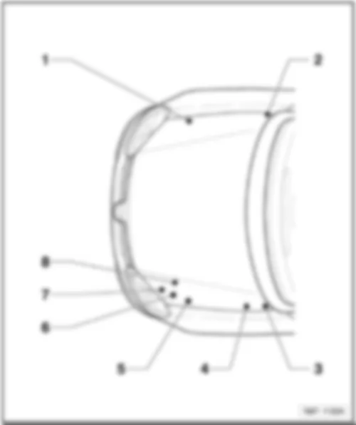
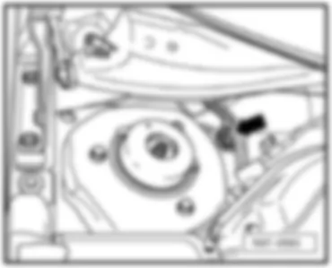
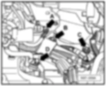
VW GOLF 2007 Overview of earth points in engine compartment
| Overview of earth points in engine compartment |


 Русский
