AUTOMOTIVE ELECTRICIANS PORTAL

VW SPACE FOX 2013 – Body electrical . Wiring diagrams, Pin Connector, Location

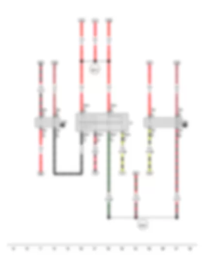
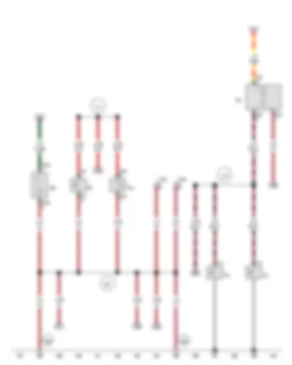
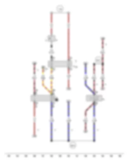
Wiring Diagram VW SPACE FOX 2013 - Battery - Starter - Alternator - Voltage regulator


Wiring Diagram  VW SPACE FOX 2013 - Battery - Starter - Alternator - Voltage regulator https://portal-diagnostov.com/license.html
https://portal-diagnostov.com/license.html Automotive Electricians Portal FZCO Automotive Electricians Portal FZCO
Download PDF file
A Battery
B Starter
C Alternator
C1 Voltage regulator
BRA5R0061804#BTJ623">J623BRA5R0061804#BTJ623"> Engine control unitBRA5R0061804#BTJ623
S162 Fuse 1 (30), in battery fuse holder
S163 Fuse 2 (30), in battery fuse holder
S269 Fuse 11 (30), in battery fuse holder
T1ay Single connector
T1j Single connector
T2ak 2-pin connector, in engine compartment
T2ar 2-pin connector
">  1 "> Earth strap, battery - bodyBRA5R0061801#VB1
">  49 "> Earth point, near ..., near batteryBRA5R0061801#VB49
  507 Threaded connection (30), on battery fuse holder
  B320 Positive connection 6 (30a) in main wiring harness

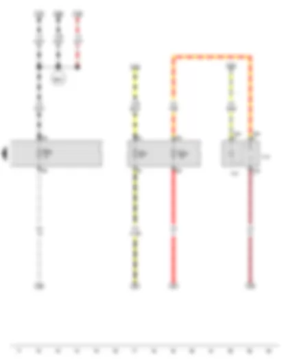
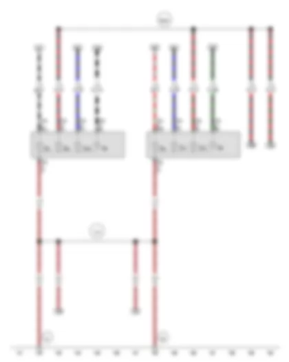
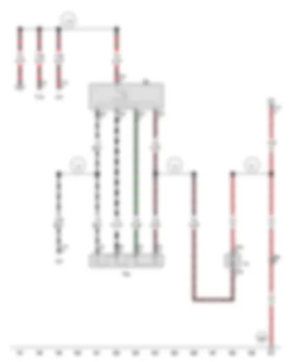
Wiring Diagram VW SPACE FOX 2013 - Ignition/starter switch - X-contact relief relay - Terminal 15 relief relay


Wiring Diagram  VW SPACE FOX 2013 - Ignition/starter switch - X-contact relief relay - Terminal 15 relief relay https://portal-diagnostov.com/license.html
https://portal-diagnostov.com/license.html Automotive Electricians Portal FZCO Automotive Electricians Portal FZCO
Få adgang til alle ledningsdiagrammer bilDownload PDF file
D Ignition/starter switch
BRA5R0061803#BTJ59">J59BRA5R0061803#BTJ59"> X-contact relief relayBRA5R0061803#BTJ59
BRA5R0061803#BTJ404">J404BRA5R0061803#BTJ404"> Terminal 15 relief relayBRA5R0061803#BTJ404
T6am 6-pin connector
T6d 6-pin connector
T9s 9-pin connector
  B272 Positive connection (30), in main wiring harness
  B346 Connection 1 (75), in main wiring harness

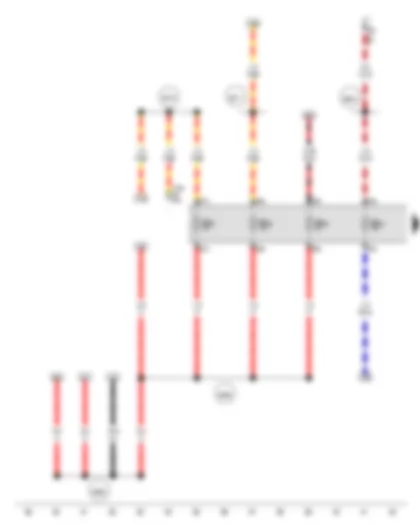
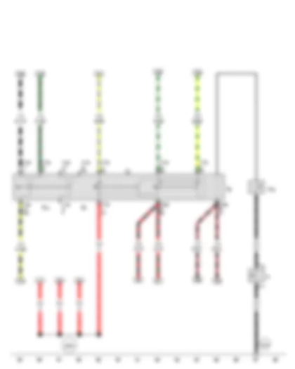
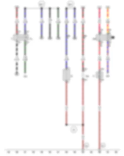
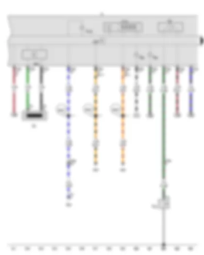
Wiring Diagram VW SPACE FOX 2013 - Fuse 27 on fuse holder B - Fuse 28 on fuse holder B - Fuse 33 on fuse holder B - Fuse 39 on fuse holder B


Wiring Diagram  VW SPACE FOX 2013 - Fuse 27 on fuse holder B - Fuse 28 on fuse holder B - Fuse 33 on fuse holder B - Fuse 39 on fuse holder B https://portal-diagnostov.com/license.html
https://portal-diagnostov.com/license.html Automotive Electricians Portal FZCO Automotive Electricians Portal FZCO
Få adgang til alle ledningsdiagrammer bilDownload PDF file
BRA5R0061803#BTJ17">J17BRA5R0061803#BTJ17"> Fuel pump relayBRA5R0061803#BTJ17
SB27 Fuse 27 on fuse holder B
SB28 Fuse 28 on fuse holder B
SB33 Fuse 33 on fuse holder B
SB39 Fuse 39 on fuse holder B
T9j 9-pin connector
T16a 16-pin connector
  B298 Positive connection 2 (30), in main wiring harness
  B299 Positive connection 3 (30), in main wiring harness
  B316 Positive connection 2 (30a) in main wiring harness
  B317 Positive connection 3 (30a) in main wiring harness
  B634 Positive connection 2 (87), in main wiring harness
*Diagnostic connection

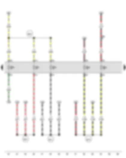
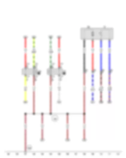
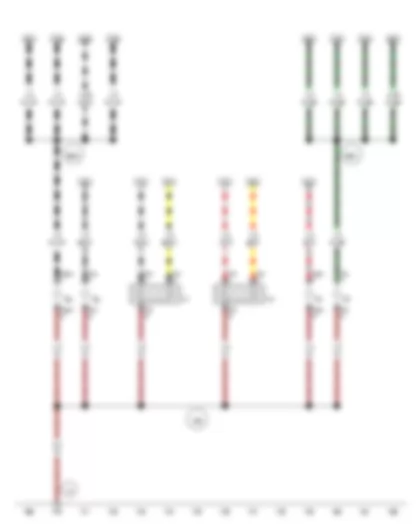
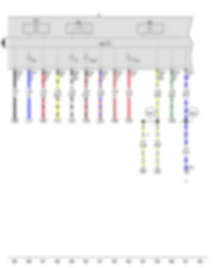
Wiring Diagram VW SPACE FOX 2013 - Fuse 31 on fuse holder B - Fuse 32 on fuse holder B - Fuse 42 on fuse holder B - Fuse 43 on fuse holder B - Fuse 48 on fuse holder B


Wiring Diagram  VW SPACE FOX 2013 - Fuse 31 on fuse holder B - Fuse 32 on fuse holder B - Fuse 42 on fuse holder B - Fuse 43 on fuse holder B - Fuse 48 on fuse holder B https://portal-diagnostov.com/license.html
https://portal-diagnostov.com/license.html Automotive Electricians Portal FZCO Automotive Electricians Portal FZCO
Få adgang til alle ledningsdiagrammer bilDownload PDF file
SB31 Fuse 31 on fuse holder B
SB32 Fuse 32 on fuse holder B
SB42 Fuse 42 on fuse holder B
SB43 Fuse 43 on fuse holder B
SB48 Fuse 48 on fuse holder B
T8d 8-pin connector, behind dash panel, centre
  B274 Positive connection (58L), in main wiring harness
  B275 Positive connection (87), in main wiring harness
  B543 Positive connection (58R), in main wiring harness
  B642 Positive connection (58), in main wiring harness

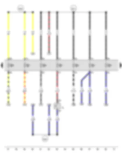
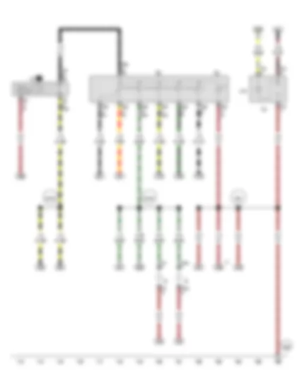
Wiring Diagram VW SPACE FOX 2013 - Reversing light switch


Wiring Diagram  VW SPACE FOX 2013 - Reversing light switch https://portal-diagnostov.com/license.html
https://portal-diagnostov.com/license.html Automotive Electricians Portal FZCO Automotive Electricians Portal FZCO
Få adgang til alle ledningsdiagrammer bilDownload PDF file
F4 Reversing light switch
SB25 Fuse 25 on fuse holder B
SB36 Fuse 36 on fuse holder B
SB37 Fuse 37 on fuse holder B
SB38 Fuse 38 on fuse holder B
SB40 Fuse 40 on fuse holder B
SB41 Fuse 41 on fuse holder B
SB47 Fuse 47 on fuse holder B
T2al 2-pin connector
  B273 Positive connection (15), in main wiring harness
  B336 Connection 2 (54), in main wiring harness
  B456 Connection (56b), in main wiring harness
*Only models with multifunction steering wheel or driver and front passenger airbags

Wiring Diagram VW SPACE FOX 2013 - Socket illumination bulb - 12 V socket 2


Wiring Diagram  VW SPACE FOX 2013 - Socket illumination bulb - 12 V socket 2 https://portal-diagnostov.com/license.html
https://portal-diagnostov.com/license.html Automotive Electricians Portal FZCO Automotive Electricians Portal FZCO
Få adgang til alle ledningsdiagrammer bilDownload PDF file
L42 Socket illumination bulb
SC2 Fuse 2 on fuse holder C
SC20 Fuse 20 on fuse holder C
SB35 Fuse 35 on fuse holder B
T3ak 3-pin connector
U18 12 V socket 2
  B643 Connection 2 (56a), in main wiring harness
*Up to November 2012

Wiring Diagram VW SPACE FOX 2013 - Light switch - Turn signal switch - Headlight dipper and flasher switch - Parking light switch - Horn plate - Horn activation contact ring


Wiring Diagram  VW SPACE FOX 2013 - Light switch - Turn signal switch - Headlight dipper and flasher switch - Parking light switch - Horn plate - Horn activation contact ring https://portal-diagnostov.com/license.html
https://portal-diagnostov.com/license.html Automotive Electricians Portal FZCO Automotive Electricians Portal FZCO
Få adgang til alle ledningsdiagrammer bilDownload PDF file
E1 Light switch
E2 Turn signal switch
E4 Headlight dipper and flasher switch
E19 Parking light switch
H Horn plate
H23 Horn activation contact ring
T1g Single connector
T1h Single connector
T12a 12-pin connector
">  678 "> Earth point, on steering wheelBRA5R0061801#VB678
  B300 Positive connection 4 (30), in main wiring harness
*Only models with multifunction steering wheel or driver and front passenger airbags

Wiring Diagram VW SPACE FOX 2013 - Fuel gauge sender - Fuel system pressurisation pump - Headlight main beam relay - Dipped beam relay


Wiring Diagram  VW SPACE FOX 2013 - Fuel gauge sender - Fuel system pressurisation pump - Headlight main beam relay - Dipped beam relay https://portal-diagnostov.com/license.html
https://portal-diagnostov.com/license.html Automotive Electricians Portal FZCO Automotive Electricians Portal FZCO
Få adgang til alle ledningsdiagrammer bilDownload PDF file
G Fuel gauge sender
G6 Fuel system pressurisation pump
BRA5R0061803#BTJ12">J12BRA5R0061803#BTJ12"> Headlight main beam relayBRA5R0061803#BTJ12
J331 Dipped beam relay
T4j 4-pin connector, near fuel pump
T10i 10-pin connector
  366 Earth connection 1, in main wiring harness
">  606 "> Earth point, under the centre console near gear stickBRA5R0061801#VB606

Wiring Diagram VW SPACE FOX 2013 - Hazard warning light switch - Hazard warning light relay - Indicator lamp for hazard warning light - Socket illumination bulb - 12 V socket - Number plate light


Wiring Diagram  VW SPACE FOX 2013 - Hazard warning light switch - Hazard warning light relay - Indicator lamp for hazard warning light - Socket illumination bulb - 12 V socket - Number plate light https://portal-diagnostov.com/license.html
https://portal-diagnostov.com/license.html Automotive Electricians Portal FZCO Automotive Electricians Portal FZCO
Få adgang til alle ledningsdiagrammer bilDownload PDF file
E3 Hazard warning light switch
J2 Hazard warning light relay
K6 Indicator lamp for hazard warning light
L42 Socket illumination bulb
T2ax 2-pin connector
T2l 2-pin connector
T3c 3-pin connector
T8e 8-pin connector
T9l 9-pin connector
U5 12 V socket
X Number plate light
  368 Earth connection 3, in main wiring harness
">  606 "> Earth point, under the centre console near gear stickBRA5R0061801#VB606
  B726 Positive connection 2 (58), in main wiring harness
  B728 Connection (49a), in main wiring harness
*Only smoker version models
*2Only models with multifunction steering wheel or driver and front passenger airbags

Wiring Diagram VW SPACE FOX 2013 - Driver door contact switch - Front passenger door contact switch - Handbrake warning switch - Brake fluid level warning contact - Front interior light - Glove compartment light


Wiring Diagram  VW SPACE FOX 2013 - Driver door contact switch - Front passenger door contact switch - Handbrake warning switch - Brake fluid level warning contact - Front interior light - Glove compartment light https://portal-diagnostov.com/license.html
https://portal-diagnostov.com/license.html Automotive Electricians Portal FZCO Automotive Electricians Portal FZCO
Få adgang til alle ledningsdiagrammer bilDownload PDF file
F2 Driver door contact switch
F3 Front passenger door contact switch
F9 Handbrake warning switch
F34 Brake fluid level warning contact
T1c Single connector
T1d Single connector
T2ai 2-pin connector
T2dg 2-pin connector
T2v 2-pin connector
T3e 3-pin connector
T16a 16-pin connector
W1 Front interior light
W6 Glove compartment light
  367 Earth connection 2, in main wiring harness
  375 Earth connection 10, in main wiring harness
  377 Earth connection 12, in main wiring harness
">  605 "> Earth point, on top end of steering columnBRA5R0061801#VB605
">  606 "> Earth point, under the centre console near gear stickBRA5R0061801#VB606
*Diagnostic connection

Wiring Diagram VW SPACE FOX 2013 - Right tail light bulb - Left tail light bulb - Rear left turn signal bulb - Rear right turn signal bulb - Left brake light bulb - Right brake light bulb - Left reversing light bulb - Right reversing light bulb


Wiring Diagram  VW SPACE FOX 2013 - Right tail light bulb - Left tail light bulb - Rear left turn signal bulb - Rear right turn signal bulb - Left brake light bulb - Right brake light bulb - Left reversing light bulb - Right reversing light bulb https://portal-diagnostov.com/license.html
https://portal-diagnostov.com/license.html Automotive Electricians Portal FZCO Automotive Electricians Portal FZCO
Få adgang til alle ledningsdiagrammer bilDownload PDF file
M2 Right tail light bulb
M4 Left tail light bulb
M6 Rear left turn signal bulb
M8 Rear right turn signal bulb
M9 Left brake light bulb
M10 Right brake light bulb
M16 Left reversing light bulb
M17 Right reversing light bulb
T5p 5-pin connector
T5q 5-pin connector
">  21 "> Earth point, near fuel pumpBRA5R0061801#VB21
">  50 "> Earth point, on left in luggage compartmentBRA5R0061801#VB50
  372 Earth connection 7, in main wiring harness
  B335 Connection 1 (54), in main wiring harness

Wiring Diagram VW SPACE FOX 2013 - Brake light switch - Brake pedal switch - Fresh air blower and radiator fan relay - Additional brake light bulb - Radiator fan - Heated rear window


Wiring Diagram  VW SPACE FOX 2013 - Brake light switch - Brake pedal switch - Fresh air blower and radiator fan relay - Additional brake light bulb - Radiator fan - Heated rear window https://portal-diagnostov.com/license.html
https://portal-diagnostov.com/license.html Automotive Electricians Portal FZCO Automotive Electricians Portal FZCO
Få adgang til alle ledningsdiagrammer bilDownload PDF file
F Brake light switch
F47 Brake pedal switch
BRA5R0061803#BTJ209">J209BRA5R0061803#BTJ209"> Fresh air blower and radiator fan relayBRA5R0061803#BTJ209
BRA5R0061804#BTJ623">J623BRA5R0061804#BTJ623"> Engine control unitBRA5R0061804#BTJ623
M25 Additional brake light bulb
T1k Single connector
T1l Single connector
T2de 2-pin connector
T2du 2-pin connector
T4m 4-pin connector
T5b 5-pin connector, behind rear left side trim, near wheel arch
T9c 9-pin connector
V7 Radiator fan
Z1 Heated rear window
">  50 "> Earth point, on left in luggage compartmentBRA5R0061801#VB50
  98 Earth connection, in rear lid wiring harness
">  671 "> Earth point 1, on front of left longitudinal memberBRA5R0061801#VB671
  B277 Positive connection 1 (15a) in main wiring harness
  B347 Connection 2 (75), in main wiring harness

Wiring Diagram VW SPACE FOX 2013 - Left headlight twin filament bulb - Right headlight twin filament bulb - Left side light bulb - Right side light bulb - Front left turn signal bulb - Front right turn signal bulb


Wiring Diagram  VW SPACE FOX 2013 - Left headlight twin filament bulb - Right headlight twin filament bulb - Left side light bulb - Right side light bulb - Front left turn signal bulb - Front right turn signal bulb https://portal-diagnostov.com/license.html
https://portal-diagnostov.com/license.html Automotive Electricians Portal FZCO Automotive Electricians Portal FZCO
Få adgang til alle ledningsdiagrammer bilDownload PDF file
L1 Left headlight twin filament bulb
L2 Right headlight twin filament bulb
M1 Left side light bulb
M3 Right side light bulb
M5 Front left turn signal bulb
M7 Front right turn signal bulb
T2am 2-pin connector
T2an 2-pin connector
T2w 2-pin connector
T2x 2-pin connector
T3h 3-pin connector
T3k 3-pin connector
">  12 "> Earth point, on left in engine compartmentBRA5R0061801#VB12
  369 Earth connection 4, in main wiring harness
  B630 Positive connection (left turn signal bulb), in main wiring harness
  B631 Positive connection (right turn signal bulb), in main wiring harness

Wiring Diagram VW SPACE FOX 2013 - Airbag coil connector and return ring with slip ring - Horn plate - Horn or dual tone horn - Dual tone horn relay


Wiring Diagram  VW SPACE FOX 2013 - Airbag coil connector and return ring with slip ring - Horn plate - Horn or dual tone horn - Dual tone horn relay https://portal-diagnostov.com/license.html
https://portal-diagnostov.com/license.html Automotive Electricians Portal FZCO Automotive Electricians Portal FZCO
Få adgang til alle ledningsdiagrammer bilDownload PDF file
F138 Airbag coil connector and return ring with slip ring
H Horn plate
H1 Horn or dual tone horn
J4 Dual tone horn relay
J879 Control unit for interactive system
T2z 2-pin connector
T5g 5-pin connector
T5k 5-pin connector
T9h 9-pin connector
T10d 10-pin connector
  109 Earth connection, in airbag wiring harness
  B279 Positive connection 3 (15a) in main wiring harness
  B727 Connection (71a), in main wiring harness
*Only models with driver and front passenger airbags
*2Only models with detachable operating unit for radio
*3Only models with multifunction steering wheel or driver and front passenger airbags

Wiring Diagram VW SPACE FOX 2013 - Fresh air blower switch - Fresh air blower series resistor with overheating fuse - Fresh air blower


Wiring Diagram  VW SPACE FOX 2013 - Fresh air blower switch - Fresh air blower series resistor with overheating fuse - Fresh air blower https://portal-diagnostov.com/license.html
https://portal-diagnostov.com/license.html Automotive Electricians Portal FZCO Automotive Electricians Portal FZCO
Få adgang til alle ledningsdiagrammer bilDownload PDF file
E9 Fresh air blower switch
BRA5R0061804#BTJ301">J301BRA5R0061804#BTJ301"> Air conditioning system control unitBRA5R0061804#BTJ301
N24 Fresh air blower series resistor with overheating fuse
T2ba 2-pin connector
T4v 4-pin connector
T5l 5-pin connector
T5m 5-pin connector
T8d 8-pin connector, behind dash panel, centre
T10f 10-pin connector
V2 Fresh air blower
V154 Fresh air and air recirculation flap control motor
  97 Earth connection 1, in air conditioning system wiring harness
">  606 "> Earth point, under the centre console near gear stickBRA5R0061801#VB606
  L6 Connection 2, in evaporator housing unit wiring harness
  L8 Connection 4, in evaporator housing unit wiring harness
  L76 Connection (87), in air conditioning system wiring harness

Wiring Diagram VW SPACE FOX 2013 - Immobiliser reader coil - Oil pressure switch - Fuel gauge - Multifunction indicator - Immobiliser control unit - Dash panel insert - Left turn signal warning lamp - Right turn signal warning lamp - Electronic power control fault lamp


Wiring Diagram  VW SPACE FOX 2013 - Immobiliser reader coil - Oil pressure switch - Fuel gauge - Multifunction indicator - Immobiliser control unit - Dash panel insert - Left turn signal warning lamp - Right turn signal warning lamp - Electronic power control fault lamp https://portal-diagnostov.com/license.html
https://portal-diagnostov.com/license.html Automotive Electricians Portal FZCO Automotive Electricians Portal FZCO
Få adgang til alle ledningsdiagrammer bilDownload PDF file
D2 Immobiliser reader coil
F22 Oil pressure switch
G1 Fuel gauge
G22 Speedometer sender
J119 Multifunction indicator
BRA5R0061804#BTJ285">J285BRA5R0061804#BTJ285"> Control unit in dash panel insertBRA5R0061804#BTJ285
J362 Immobiliser control unit
BRA5R0061804#BTJ623">J623BRA5R0061804#BTJ623"> Engine control unitBRA5R0061804#BTJ623
K Dash panel insert
K65 Left turn signal warning lamp
K94 Right turn signal warning lamp
K132 Electronic power control fault lamp
T1a Single connector
T2j 2-pin connector
T3i 3-pin connector
T14a 14-pin connector, on left in engine compartment
T32a 32-pin connector
  B383 Connection 1 (powertrain CAN bus, high), in main wiring harness
  B390 Connection 1 (powertrain CAN bus, low), in main wiring harness
  B464 Connection (speed signal), in main wiring harness

Wiring Diagram VW SPACE FOX 2013 - Coolant temperature gauge - Rev. counter - Speedometer - Control unit in dash panel insert - Dash panel insert - Main beam warning lamp - Alternator warning lamp - Reserve fuel warning lamp - Brake system warning lamp


Wiring Diagram  VW SPACE FOX 2013 - Coolant temperature gauge - Rev. counter - Speedometer - Control unit in dash panel insert - Dash panel insert - Main beam warning lamp - Alternator warning lamp - Reserve fuel warning lamp - Brake system warning lamp https://portal-diagnostov.com/license.html
https://portal-diagnostov.com/license.html Automotive Electricians Portal FZCO Automotive Electricians Portal FZCO
Få adgang til alle ledningsdiagrammer bilDownload PDF file
G3 Coolant temperature gauge
G5 Rev. counter
G21 Speedometer
BRA5R0061804#BTJ285">J285BRA5R0061804#BTJ285"> Control unit in dash panel insertBRA5R0061804#BTJ285
K Dash panel insert
K1 Main beam warning lamp
K2 Alternator warning lamp
K105 Reserve fuel warning lamp
K118 Brake system warning lamp
T16a 16-pin connector
T32a 32-pin connector
  B340 Connection 1 (58d), in main wiring harness
  B625 Connection (K-diagnosis wire), in main wiring harness
*Only smoker version models
*2Diagnostic connection
*3Up to November 2012


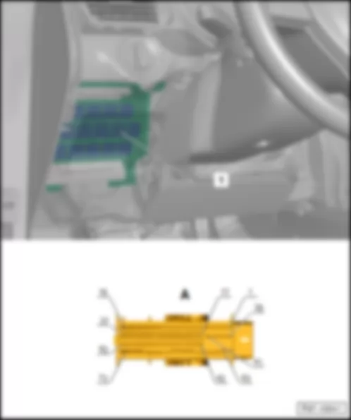
VW SPACE FOX 2013 ABS control unit J104

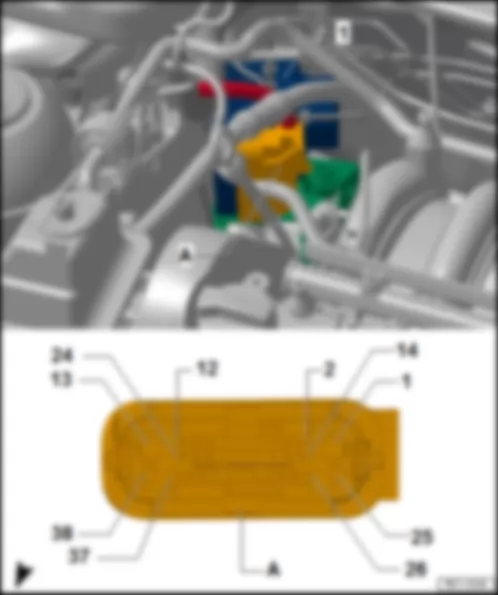
ABS control unit -J104-
Fitting Location:
VW SPACE FOX 2013 ABS control unit J104 https://portal-diagnostov.com/license.html
https://portal-diagnostov.com/license.html Automotive Electricians Portal FZCO Automotive Electricians Portal FZCO
Få adgang til alle ledningsdiagrammer bilDownload PDF file
1 -  ABS control unit -J104-
A -  38-pin connector, in the ABS control unit -T38a-

   
Connector description: ABS control unit -J104-
T38a - Function
1 - Fuse 5 (30) of the battery fuse holder -S177-
2 - --
3 - --
4 - Front right wheel rotation sensor -G45-
5 - --
6 - --
7 - --
8 - Front left wheel rotation sensor -G47-
9 - --
10 - --
11 - --
12 - --
13 - Terminal 31
14 - CAN-Bus, Low
15 - --
16 - Front right wheel rotation sensor -G45-
17 - Rear right wheel rotation sensor -G44-
18 - Rear left wheel rotation sensor -G46-
19 - Front left wheel rotation sensor -G47-
20 - --
21 - --
22 - --
23 - --
24 - --
25 - Fuse 12 (30) of the battery fuse holder -S270-
26 - CAN-Bus, High
27 - --
28 - Fuse 24 of fuse holder A -SA24-
29 - Rear right wheel rotation sensor -G44-
30 - Brake pedal switch -F47- , Brake light switch -F- , Engine control unit -J623-
31 - Rear left wheel rotation sensor -G46-
32 - --
33 - --
34 - --
35 - --
36 - --
37 - --
38 - Terminal 31

   
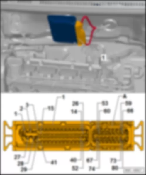
Automatic gearbox control unit -J217-
Fitting Location:
VW SPACE FOX 2013 ABS control unit J104 https://portal-diagnostov.com/license.html
https://portal-diagnostov.com/license.html Automotive Electricians Portal FZCO Automotive Electricians Portal FZCO
Få adgang til alle ledningsdiagrammer bilDownload PDF file
1 -  Automatic gearbox control unit -J217-
A -  80-pin connector, in the automatic gearbox control unit -T80b-

   
Connector Description: Automatic gearbox control unit -J217-
T80b - Function
1 - Terminal 31
2 - Terminal 31, Electrovalves
3 - --
4 - --
5 - --
6 - --
7 - --
8 - --
9 - --
10 - --
11 - --
12 - Gear identification sensor -G604-
13 - Gear identification sensor -G604-
14 - --
15 - --
16 - --
17 - --
18 - --
19 - --
20 - --
21 - --
22 - --
23 - --
24 - Gear identification sensor -G604-
25 - Gear identification sensor -G604-
26 - --
27 - Fuse 8 (30) of the battery fuse holder -S180-
28 - Fuse 9 of fuse holder A -SA9-
29 - Gear selection valve 3 -N286-
30 - --
31 - Gearbox hydraulic pump relay -J510-
32 - Gear selection valve 1 -N284-
33 - CAN-Bus, Low
34 - Gear identification sensor 2 -G616-
35 - Gear identification sensor 2 -G616-
36 - --
37 - --
38 - Gearbox intake rotation sensor -G182-
39 - --
40 - Gearbox hydraulic pressure sensor -G270-
41 - --
42 - Engine control unit -J623-
43 - Clutch actuator valve -N255-
44 - Gear selection valve 2 -N285-
45 - CAN-Bus, High
46 - Gear identification sensor 2 -G616-
47 - Gear identification sensor 2 -G616-
48 - --
49 - Diagnosis terminal - K
50 - Gearbox intake rotation sensor -G182-
51 - --
52 - Clutch position sensor -G476-
53 - --
54 - --
55 - --
56 - --
57 - --
58 - --
59 - Gearbox hydraulic pressure sensor -G270-
60 - --
61 - Clutch position sensor -G476-
62 - Handbrake control switch -F9- , Instrument cluster -K-
63 - --
64 - --
65 - Clutch position sensor -G476-
66 - --
67 - --
68 - --
69 - Onboard network control unit -J519-
70 - --
71 - --
72 - --
73 - Clutch position sensor -G476-
74 - --
75 - --
76 - Terminal 50, Onboard network control unit -J519-
77 - --
78 - --
79 - Gearbox hydraulic pressure sensor -G270-
80 - --

   
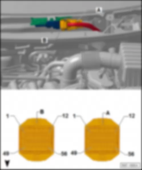
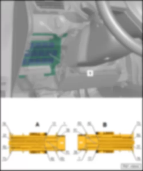
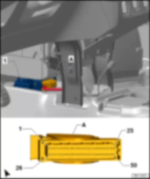
Engine control unit -J623-
Fitting Location:
VW SPACE FOX 2013 ABS control unit J104 https://portal-diagnostov.com/license.html
https://portal-diagnostov.com/license.html Automotive Electricians Portal FZCO Automotive Electricians Portal FZCO
Få adgang til alle ledningsdiagrammer bilDownload PDF file
1 -  Engine control unit -J623-
A -  56-pin connector -T56a-
B -  56-pin connector -T56b-

   
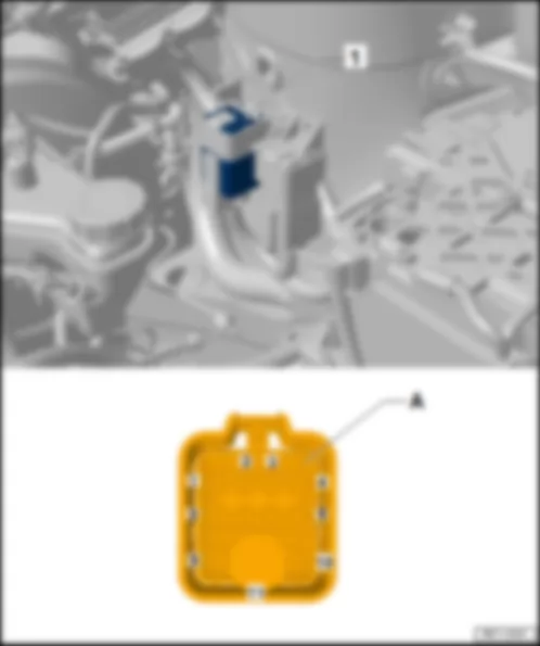
Heating system control unit -J65-
Fitting Location:
VW SPACE FOX 2013 ABS control unit J104 https://portal-diagnostov.com/license.html
https://portal-diagnostov.com/license.html Automotive Electricians Portal FZCO Automotive Electricians Portal FZCO
Få adgang til alle ledningsdiagrammer bilDownload PDF file
1 -  Heating system control unit -J65-
A -  11-pin connector -T11a-

   
Connector description: Heating system control unit -J65-
T11a - Function
1 - Fuel preheating resistance -Z66-
2 - Fuel preheating resistance 2 -Z108-
3 - Fuel preheating resistance 3 -Z109-
4 - --
5 - --
6 - Spark plugs relay -J52-
7 - --
8 - --
9 - --
10 - Engine control unit -J623-
11 - Spark plugs relay -J52-


VW SPACE FOX 2013 Engine compartment earth points

Engine compartment earth points
VW SPACE FOX 2013 Engine compartment earth points https://portal-diagnostov.com/license.html
https://portal-diagnostov.com/license.html Automotive Electricians Portal FZCO Automotive Electricians Portal FZCO
Få adgang til alle ledningsdiagrammer bilDownload PDF file
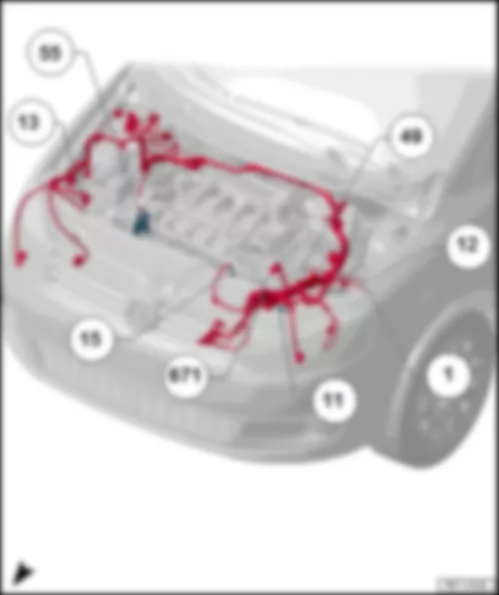
   1 Ground cable, battery-body
   11 Battery housing earth points
   12 Engine comp. left earth points
   13 Engine comp. right earth points
   15 Head earth points
   49 Earth points, next to the battery
   55 Earth points next to the ABS control unit
   671 Earth point 1 on the front left side member

   
Vehicle interior earth points
VW SPACE FOX 2013 Engine compartment earth points https://portal-diagnostov.com/license.html
https://portal-diagnostov.com/license.html Automotive Electricians Portal FZCO Automotive Electricians Portal FZCO
Få adgang til alle ledningsdiagrammer bilDownload PDF file
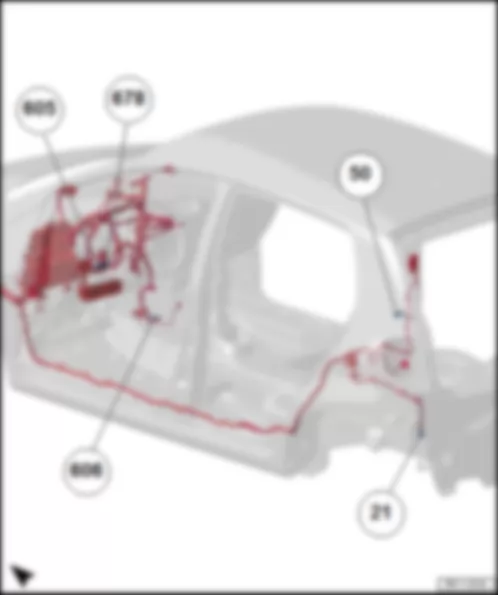
   21 Earth points next to the fuel pump
   50 Left boot earth points
   605 Earth point on the upper steering column region
   606 Earth point under the central console, next to the selector lever
   678 Steering wheel earth point


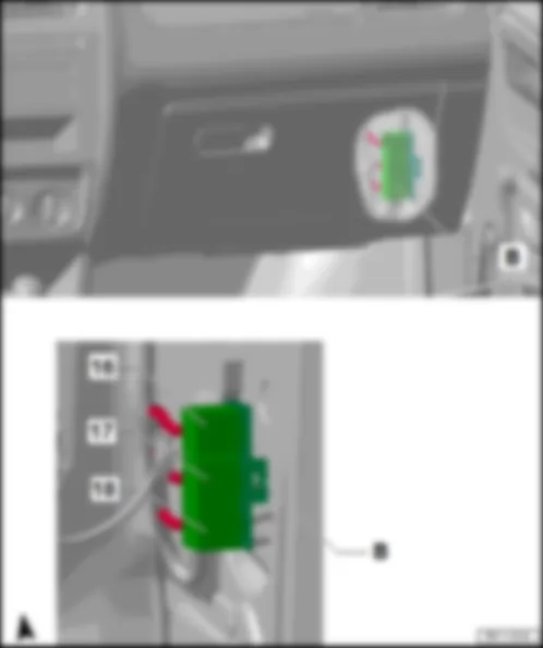
VW SPACE FOX 2013 Relay to the right of the dashboard, behind the glove compartment

Relay to the right of the dashboard, behind the glove compartment
Relay descriptions, as of April 2013:
VW SPACE FOX 2013 Relay to the right of the dashboard, behind the glove compartment https://portal-diagnostov.com/license.html
https://portal-diagnostov.com/license.html Automotive Electricians Portal FZCO Automotive Electricians Portal FZCO
Få adgang til alle ledningsdiagrammer bilDownload PDF file
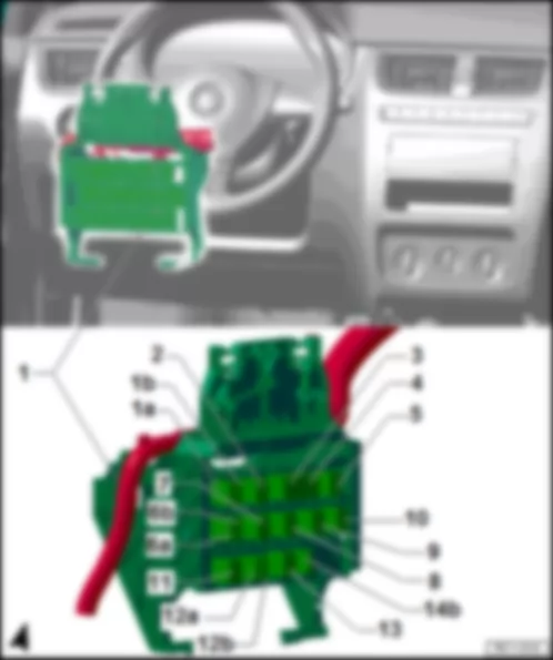
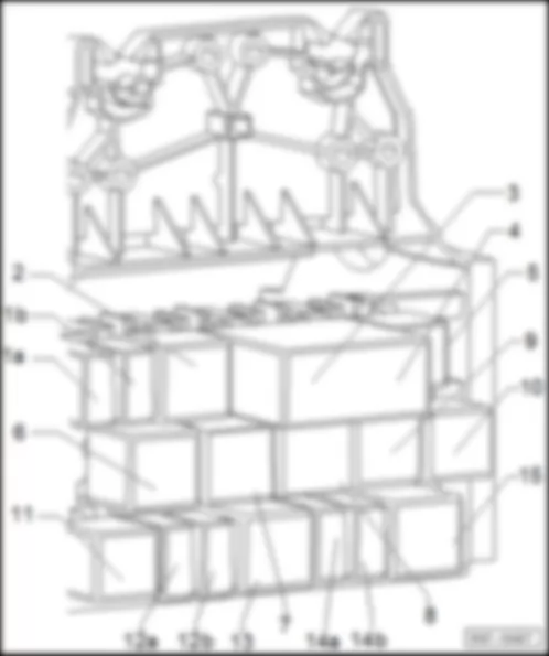
Relay to the left, behind the dashboard
Relay descriptions, as of April 2013:
VW SPACE FOX 2013 Relay to the right of the dashboard, behind the glove compartment https://portal-diagnostov.com/license.html
https://portal-diagnostov.com/license.html Automotive Electricians Portal FZCO Automotive Electricians Portal FZCO
Få adgang til alle ledningsdiagrammer bilDownload PDF file
1b -  Relief relay 2 of contact X -J339-
q   Colour: Black
3 -  External side mirror folding control unit -J351-
q   Colour: Black
4 -  External side mirror folding control unit -J351-
q   Colour: Black
6a -  Alarm horn relay -J641-
q   Colour: Gray
7 -  Gearbox hydraulic pump relay -J510-
q   Colour: Light-green
9 -  Radiator fan and natural air fan relay -J209-
q   Colour: Black
11 -  Fuel pump relay -J17-
q   Colour: Black
12b -  Fog lights relay -J5-
q   Colour: Black
14b -  Headlights relay -J12-
q   Colour: Gray


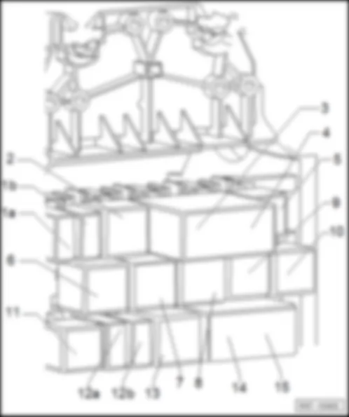
VW SPACE FOX 2013 Relay to the left, behind the dashboard

Relay to the left, behind the dashboard
Description of relays from January 2011 until April 2012:
VW SPACE FOX 2013 Relay to the left, behind the dashboard https://portal-diagnostov.com/license.html
https://portal-diagnostov.com/license.html Automotive Electricians Portal FZCO Automotive Electricians Portal FZCO
Få adgang til alle ledningsdiagrammer bilDownload PDF file
1a -  Air conditioning system cut-off relay -J365-
q   Colour: Gray
1b -  Relief relay 2 of contact X -J339-
q   Colour: Black
2 -  Starter relay -J53-
q   Colour: Black
3 -  External side mirror folding control unit -J351-
q   Colour: Black
4 -  External side mirror folding control unit -J351-
q   Colour: Black
5 -  Empty
 -  Fog lights relay -J5-1)
q   Colour: Blue
6 -  Rear window heating system regulator relay -J48-
q   Colour: Blue
7 -  Gearbox hydraulic pump relay -J510-2)
q   Colour: Black
8 -  Relief relay for contact X -J59-
q   Colour: Gray
9 -  Radiator fan and natural air fan relay -J209-
q   Colour: Black
10 -  Radiator fan's 2nd speed relay -J101-
q   Colour: Black
11 -  Fuel pump relay -J17-
q   Colour: Black
12a -  Double horn relay -J4-
q   Colour: Gray
12b -  Cold start device relay -J41-
q   Colour: Black
13 -  Starter relay 2 -J695-
q   Colour: Black
14a -  Low beam relay -J331-
q   Colour: Gray
14b -  Headlight relay -J12-
q   Colour: Gray
15 -  Automatic intermittent wiper and washer system relay -J31-
q   Colour: Red

  Note
t  1) Only for CROSS vehicles
t  2) As of October, 2011
   
Description of relays from January 2011 until April 2012:
VW SPACE FOX 2013 Relay to the left, behind the dashboard https://portal-diagnostov.com/license.html
https://portal-diagnostov.com/license.html Automotive Electricians Portal FZCO Automotive Electricians Portal FZCO
Få adgang til alle ledningsdiagrammer bilDownload PDF file
1a -  Air conditioning system cut-off relay -J365-
q   Colour: Gray
1b -  Relief relay 2 of contact X -J339-
q   Colour: Black
2 -  Starter relay -J53-
q   Colour: Black
3 -  External side mirror folding control unit -J351-
q   Colour: Black
4 -  External side mirror folding control unit -J351-
q   Colour: Black
5 -  Empty
 -  Fog lights relay -J5-1)
q   Colour: Blue
6 -  Rear window heating system regulator relay -J48-
q   Colour: Blue
7 -  Gearbox hydraulic pump relay -J510-2)
q   Colour: Black
8 -  Relief relay for contact X -J59-
q   Colour: Gray
9 -  Radiator fan and natural air fan relay -J209-
q   Colour: Black
10 -  Radiator fan's 2nd speed relay -J101-
q   Colour: Black
11 -  Fuel pump relay -J17-
q   Colour: Black
12a -  Double horn relay -J4-
q   Colour: Gray
12b -  Cold start device relay -J41-
q   Colour: Black
13 -  Starter relay 2 -J695-
q   Colour: Black
14 -  Automatic intermittent wiper and washer system control unit -J932-
q   Colour: Dark-gray
15 -  Automatic intermittent wiper and washer system control unit -J932-
q   Colour: Dark-gray

  Note
t  1) Only for CROSS vehicles
t  2) As of October, 2011
   
Relay to the left, behind the dashboard
Relay descriptions, as of April 2012:
VW SPACE FOX 2013 Relay to the left, behind the dashboard https://portal-diagnostov.com/license.html
https://portal-diagnostov.com/license.html Automotive Electricians Portal FZCO Automotive Electricians Portal FZCO
Få adgang til alle ledningsdiagrammer bilDownload PDF file
1b -  Relief relay 2 of contact X -J339-
q   Colour: Black
3 -  External side mirror folding control unit -J351-
q   Colour: Black
4 -  External side mirror folding control unit -J351-
q   Colour: Black
5 -  Empty
6 -  Rear window heating system regulator relay -J48-
q   Colour: Blue
8 -  Relief relay for contact X -J59-
q   Colour: Gray
10 -  Radiator fan's 2nd speed relay -J101-
q   Colour: Black
12a -  Double horn relay -J4-
q   Colour: Gray
13 -  Relief relay of terminal 15 -J404-
q   Colour: Black
14b -  Headlight relay -J12-
q   Colour: Gray
VW SPACE FOX 2013 Relay to the left, behind the dashboard https://portal-diagnostov.com/license.html
https://portal-diagnostov.com/license.html Automotive Electricians Portal FZCO Automotive Electricians Portal FZCO
Få adgang til alle ledningsdiagrammer bilDownload PDF file
1a -  Air conditioning system cut-off relay -J365-
q   Colour: Gray
1b -  Relief relay 2 of contact X -J339-
q   Colour: Black
2 -  Starter relay -J53-
q   Colour: Black
3 -  External side mirror folding control unit -J351-
q   Colour: Black
4 -  External side mirror folding control unit -J351-
q   Colour: Black
5 -  Empty
 -  Fog lights relay -J5-1)
q   Colour: Blue
6 -  Rear window heating system regulator relay -J48-
q   Colour: Blue
7 -  Gearbox hydraulic pump relay -J510-
q   Colour: Black
8 -  Relief relay for contact X -J59-
q   Colour: Gray
9 -  Radiator fan and natural air fan relay -J209-
q   Colour: Black
10 -  Radiator fan's 2nd speed relay -J101-
q   Colour: Black
11 -  Fuel pump relay -J17-
q   Colour: Black
12a -  Double horn relay -J4-
q   Colour: Gray
12b -  Cold start device relay -J41-
q   Colour: Gray
13 -  Relief relay of terminal 15 -J404-
q   Colour: Black
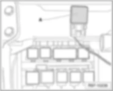
Relay over the relay-holder
Relay description:
VW SPACE FOX 2013 Relay to the left, behind the dashboard https://portal-diagnostov.com/license.html
https://portal-diagnostov.com/license.html Automotive Electricians Portal FZCO Automotive Electricians Portal FZCO
Få adgang til alle ledningsdiagrammer bilDownload PDF file
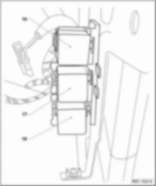
Relay to the right of the dashboard, behind the glove compartment
Relay description:
VW SPACE FOX 2013 Relay to the left, behind the dashboard https://portal-diagnostov.com/license.html
https://portal-diagnostov.com/license.html Automotive Electricians Portal FZCO Automotive Electricians Portal FZCO
Få adgang til alle ledningsdiagrammer bilDownload PDF file
16 -  Starter relay -J53-2)
q   Colour: Black

VW SPACE FOX 2013 Onboard network control unit: BFM J519

Onboard network control unit: BFM -J519-
Fitting Location:
VW SPACE FOX 2013 Onboard network control unit: BFM J519 https://portal-diagnostov.com/license.html
https://portal-diagnostov.com/license.html Automotive Electricians Portal FZCO Automotive Electricians Portal FZCO
Få adgang til alle ledningsdiagrammer bilDownload PDF file
1 -  Onboard network control unit -J519-
A -  73-pole fitting connector in the onboard control unit -T73a-

   
Connector description: Onboard network control unit: BFM -J519-
T73a - Function
1 - Windscreen wiper motor -V-
2 - Windscreen wiper motor -V-
3 - Terminal 31
4 - Front interior light -W1-
5 - --
6 - --
7 - --
8 - --
9 - Terminal 30, Fuse 40 in fuse holder B -SB40-
10 - Rear tailgate unlocking motor -V139- , Central control unit for window control -J1015-
11 - Terminal 31
12 - Terminal 30, Fuse 16 in fuse holder A -SA16-
13 - --
14 - Terminal 31
15 - Rear right central locking system motor -V308- , Driver door central locking system motor -V302- , Rear left central locking system motor -V307-
16 - Passenger door central locking system motor -V303- , Rear right central locking system motor -V308-
17 - --
18 - --
19 - --
20 - Central control unit for window control -J1015- , Alarm system ultrasound sensor -G209- , Rear window wiper motor -E34-
21 - Rear window heating system switch -E230-
22 - --
23 - --
24 - Alarm horn relay -J641-
25 - Warning light switch -E3-
26 - Instrument cluster -K-
27 - Diagnosis terminal - CAN High
28 - Diagnosis terminal - CAN Low
29 - CAN-Bus, High
30 - CAN-Bus, Low
31 - Front lid / engine lid contact switch for the alarm system -F120-
32 - Int. locking switch, driver side -E150-
33 - Alarm system ultrasound sensor -G209-
34 - Rear tailgate unlocking switch -E165-
35 - Driver door central locking system motor -V302-
36 - Driver door central locking system motor -V302-
37 - Central control unit for window control -J1015- , Rear tailgate unlocking motor -V139-
38 - Terminal 31
39 - --
40 - --
41 - --
42 - Terminal 30, Fuse 9 (30) of the battery fuse holder -S267-
43 - Terminal31
44 - Windscreen wiper motor -V-
45 - Engine control unit -J623- , Brake pedal switch -F47-
46 - Windscreen wiper delay relay switch (intermittent operation) -E22-
47 - Windscreen wiper delay relay switch (intermittent operation) -E22-
48 - External side mirror folding control unit -J351- , Reverse gear light switch -F4-
49 - Instrument cluster -K-
50 - Generator (Alternator) -C- , Voltage regulator -C1-
51   Terminal 15, Fuse 38 in fuse holder B -SB38- , Relief relay of terminal 15 -J404-
52 - Terminal 50, Automatic gearbox control unit -J217-
53 - Terminal S, Fuse 2 in fuse holder A -SA2-
54 - Rear window wiper motor -V12- , Rear window and windscreen washer pump -V59-
55 - Rear window heating system switch -E230-
56 - Windscreen wiper delay relay switch (intermittent operation) -E22-
57 - Turn light/flashing light switch -E2-
58 - Turn light/flashing light switch -E2-
59 - Contact of the airbag coil and return spring with slip ring -F138-
60 - Warning light switch -E3-
61 - Driver door contact switch -F2-
62 - Passenger door contact switch -F3- , Rear left door contact switch -F10- , Rear right door contact switch -F11-
63 - Terminal 30, Fuse 29 in fuse holder B -SB29-
64 - Front right turn signal lamp -M7-
65 - Fuse 25 in fuse holder B -SB25-
66 - Front left turn signal lamp -M5-
67 - Horn and double horn -H1-
68 - Fuse 41 in fuse holder B -SB41-
69 - Left brake light lamp -M9- , Right brake light lamp -M10-
70 - --
71 - --
72 - Rear window defogger -Z1-
73 - Fuse 6 of fuse holder A -SA6-

   
Onboard network control unit: BCM -J519-
Fitting Location:
VW SPACE FOX 2013 Onboard network control unit: BFM J519 https://portal-diagnostov.com/license.html
https://portal-diagnostov.com/license.html Automotive Electricians Portal FZCO Automotive Electricians Portal FZCO
Få adgang til alle ledningsdiagrammer bilDownload PDF file
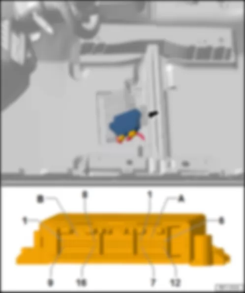
1 -  Onboard network control unit -J519-
A -  73-pole fitting connector in the onboard control unit -T73b-
B -  73-pole fitting connector in the onboard control unit -T73c-

   
Connector description: Onboard network control unit: BCM -J519-
T73b - Function - T73c - Function
1 - Headlights relay -J12- - 1 - --
2 - Left low beam lamp -M29- , Sealed left headlight double-filament lamp -L1- - 2 - Sealed right headlight double-filament lamp -L2- , Right low beam lamp -M31-
3 - -- - 3 - --
4 - Internal lighting, Front internal light -W1- - 4 - Instrument cluster -K-
5 - -- - 5 - --
6 - Fog light lamp -L20- , Fog lights switch -E23- , Instrument cluster -K- - 6 - --
7 - Fog lights switch -E23- - 7 - License plate light -X-
8 - -- - 8 - --
9 - -- - 9 - Left fog light and long-range headlight lamp -M94- , Right fog light lamp -L23-
10 - Rear tailgate unlocking motor -V139- , Central control unit for window control -J1015- , Spare wheel unlocking motor -V340- - 10 - Right fog light and long-range headlight lamp -M95- , Left fog light lamp -L22-
11 - Passenger door central locking system motor -V303- , Driver door central locking system motor -V302- , Rear left central locking system motor -V307- , Rear right central locking system motor -V308- - 11 - Terminal 30, Fuse 1 in fuse holder A -SA1-
12 - Driver door central locking system motor -V302- - 12 - --
13 - -- - 13 - Terminal 30, Fuse 25 in fuse holder B -SB25-
14 - Terminal 31 - 14 - Front left turn signal lamp -M5- , Rear left turn signal lamp -M6-
15 - Passenger door central locking system motor -V303- , Driver door central locking system motor -V302- , Rear left central locking system motor -V307- , Rear right central locking system motor -V308- - 15 - Front right turn signal lamp -M7- , Rear right turn signal lamp -M8-
16 - Terminal 30, Fuse 16 in fuse holder A -SA16- - 16 - Left brake light lamp -M9- , Right brake light lamp -M10- , Automatic gearbox control unit -J217-
17 - Driver door central locking system motor -V302- - 17 - Central control unit for window control -J1015- , Alarm system ultrasound sensor -G209- , Rear window wiper motor -E34-
18 - Driver door central locking system motor -V302- - 18 - CAN-Bus, Low
19 - Driver door contact switch -F2- - 19 - CAN-Bus, High
20 - Passenger door contact switch -F3- - 20 - Radio -R-
21 - Driver door central locking system motor -V302- - 21 - Radio -R-
22 - Driver door central locking system motor -V302- - 22 - Diagnosis terminal, CAN-Low
23 - Rear tailgate unlocking switch -E165- , Spare wheel unlocking switch -E405- , Spare wheel unlocking support switch -E727- - 23 - Diagnosis terminal, CAN-High
24 - Driver door central locking system motor -V302- - 24 - Right alarm ultrasound sensor -G171- , Alarm system ultrasound sensor -G209- , Rain sensor and photodetector -G397-
25 - Int. locking switch, driver side -E150- - 25 - --
26 - Rear right door contact switch -F11- - 26 - --
27 - Front lid / engine lid contact switch for the alarm system -F120- - 27 - Windscreen wiper delay relay switch (intermittent operation) -E22-
28 - Warning light switch -E3- - 28 - --
29 - Contact of the airbag coil and return spring with slip ring -F138- - 29 - --
30 - Central control unit for window control -J1015- , Rear tailgate unlocking motor -V139- - 30 - Left alarm ultrasound sensor -G170-
31 - -- - 31 - Rear window heating system switch -E230-
32 - Turn light/flashing light switch -E2- - 32 - Windscreen wiper motor -V-
33 - Turn light/flashing light switch -E2- - 33 - --
34 - Rear left door contact switch -F10- - 34 - Instrument cluster -K- , Light switch illumination lamp -L9- ,
35 - Sunroof movement control unit -J245- - 35 - --
36 - -- - 36 - --
37 - Light switch -E1- - 37 - --
38 - -- - 38 - Terminal 31
39 - Terminal 31 - 39 - Terminal 30, Fuse 40 in fuse holder B -SB40-
40 - Front right side lamp -M3- , Rear right lamp -M2- - 40 - Terminal 31
41 - Front left side lamp -M1- , Rear left lamp -M4- - 41 - --
42 - Terminal S, Fuse 2 in fuse holder A -SA2- - 42 - --
43 - Engine control unit -J623- , Brake pedal switch -F47- - 43 - Light switch -E1-
44 - Terminal 15, Fuse 38 in fuse holder B -SB38- , Relief relay of terminal 15 -J404- - 44 - --
45 - Light switch -E1- - 45 - --
46 - -- - 46 - --
47 - -- - 47 - --
48 - Sunroof movement control unit -J245- - 48 - External side mirror folding control unit -J351- , Reverse gear light switch -F4- , Left reverse gear light lamp -M16- , Right reverse gear light lamp -M17-
49 - -- - 49 - Generator (Alternator) -C- , Voltage regulator -C1-
50 - -- - 50 - Automatic gearbox control unit -J217- , Starter -B- , Ignition switch -D- , Engine control unit -J623-
51 - -- - 51 - Ignition switch -D- , Relief relay for contact X -J59- , Relief relay 2 of contact X -J339-
52 - -- - 52 - Light switch -E1-
53 - Alarm horn relay -J641- - 53 - Windscreen wiper delay relay switch (intermittent operation) -E22-
54 - -- - 54 - CAN-Bus, High
55 - -- - 55 - --
56 - Warning light switch -E3- - 56 - --
57 - Left alarm ultrasound sensor -G170- - 57 - CAN-Bus, Low
58 - Instrument cluster -K- - 58 - --
59 - -- - 59 - Terminal 30, Fuse 9 (30) of the battery fuse holder -S267-
60 - Rear window heating system switch -E230- - 60 - Terminal 31
61 - -- - 61 - Rear window wiper motor -V12- , Rear window and windscreen washer pump -V59- , Windscreen wiper delay relay control -E38-
62 - Relay 2 for long-range headlights -J1062- , Fog lights relay -J5- , Turn light/flashing light switch -E2- - 62 - Windscreen wiper delay relay switch (intermittent operation) -E22-
63 - Terminal 30, Fuse 36 in fuse holder B -SB36- - 63 - Rear window defogger -Z1-
64 - -- - 64 - --
65 - Internal lighting, Rear left reading light -W11- , Rear right reading lamp -W12- - 65 - --
66 - Internal lighting, Alarm system ultrasound sensor -G209- , Right alarm ultrasound sensor -G171- , Rain sensor and photodetector -G397- - 66 - --
67 - -- - 67 - Terminal 30, Fuse 6 in fuse holder A -SA6-
68 - Terminal 30, Fuse 29 in fuse holder B -SB29- - 68 - Terminal 30, Fuse 47 in fuse holder B -SB47-
69 - Windscreen wiper motor -V- - 69 - --
70 - Terminal 31 - 70 - --
71 - Windscreen wiper motor -V- - 71 - --
72 - Horn and double horn -H1- - 72 - --
73 - Terminal 30, Fuse 41 in fuse holder B -SB41- - 73 - --

   
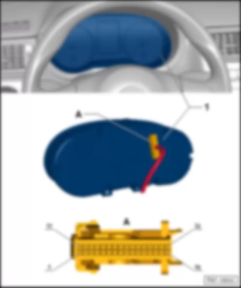
Instrument cluster indicator control unit -J285-
Fitting Location:
VW SPACE FOX 2013 Onboard network control unit: BFM J519 https://portal-diagnostov.com/license.html
https://portal-diagnostov.com/license.html Automotive Electricians Portal FZCO Automotive Electricians Portal FZCO
Få adgang til alle ledningsdiagrammer bilDownload PDF file
1 -  Instrument cluster indicator control unit -J285-
A -  32-pole fitting connector in the instrument cluster -T32a-

   
Connector description: Instrument cluster indicator control unit -J285-
T32a - Function
1 - Fuel gauge sensor
2 - --
3 - --
4 - Terminal 58d
5 - Terminal 58
6 - --
7 - Immobilizer reading coil
8 - Immobilizer reading coil
9 - Speed sensor
10 - --
11 - --
12 - --
13 - Fog lights
14 - Headlights
15 - Alarm
16 - Terminal 31
17 - --
18 - --
19 - External temperature sensor
20 - Terminal 31, Sensors mass
21 - Multifunctional (MFA) above
22 - Multifunctional (MFA) below
23 - Multifunctional (MFA) enter
24 - --
25 - Handbrake control switch
26 - Brake oil level warning contact
27 - Oil pressure switch
28 - CAN-Bus, High
29 - CAN-Bus, Low
30 - --
31 - Terminal 15
32 - Terminal 30

   
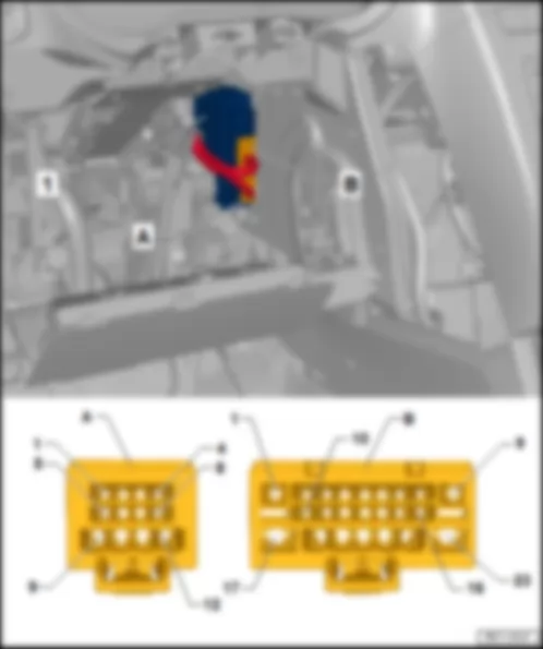
Central control unit for window control -J1015-
Fitting Location:
VW SPACE FOX 2013 Onboard network control unit: BFM J519 https://portal-diagnostov.com/license.html
https://portal-diagnostov.com/license.html Automotive Electricians Portal FZCO Automotive Electricians Portal FZCO
Få adgang til alle ledningsdiagrammer bilDownload PDF file
1 -  Central control unit for window control -J1015-
A -  12-pole fitting connector in the window control central control unit -T12g-
B -  23-pole fitting connector in the window control central control unit -T23b-

   
Connector description: Central control unit for window control -J1015-
T12g - Function - T23b - Function
1 - Rear window control blocking switch -E39- - 1 - Terminal 31
2 - Rear window control blocking switch -E39- - 2 - Onboard network control unit -J519-
3 - -- - 3 - --
4 - Rear window control blocking switch -E39- - 4 - --
5 - Rear left window control switch, driver side -E53- - 5 - --
6 - Rear left window control switch -E52- - 6 - --
7 - Rear left window control switch, driver side -E53- - 7 - Front right window control switch, driver side -E81-
8 - Rear right window control switch -E54- - 8 - --
9 - Rear left window control motor -V26- - 9 - Terminal 31
10 - Rear left window control motor -V26- - 10 - --
11 - Rear right window control motor -V27- - 11 - --
12 - Rear right window control motor -V27- - 12 - Diagnosis terminal - K
-- - -- - 13 - --
  - -- - 14 - --
-- - -- - 15 - Front right window control switch, driver side -E81-
-- - -- - 16 - Passenger door window control switch -E107-
-- - -- - 17 - --
-- - -- - 18 - --
-- - -- - 19 - Driver window control motor -V147-
-- - -- - 20 - Driver window control motor -V147-
-- - -- - 21 - Passenger window activation motor -V148-
-- - -- - 22 - Passenger window activation motor -V148-
-- - -- - 23 - Terminal 30, Fuse 22 in fuse holder A -SA22-

   
Airbag control unit -J234-
Fitting Location:
VW SPACE FOX 2013 Onboard network control unit: BFM J519 https://portal-diagnostov.com/license.html
https://portal-diagnostov.com/license.html Automotive Electricians Portal FZCO Automotive Electricians Portal FZCO
Få adgang til alle ledningsdiagrammer bilDownload PDF file
1 -  Airbag control unit -J234-
A -  50-pin connector in the airbag control unit -T50a-

   
Air conditioning control unit -J301-
Fitting Location:
VW SPACE FOX 2013 Onboard network control unit: BFM J519 https://portal-diagnostov.com/license.html
https://portal-diagnostov.com/license.html Automotive Electricians Portal FZCO Automotive Electricians Portal FZCO
Få adgang til alle ledningsdiagrammer bilDownload PDF file
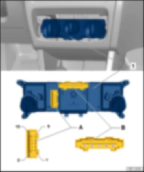
1 -  Air conditioning control unit -J301-
A -  10-pin connector in the air conditioning control unit -T10f-
B -  5-pin connector in the natural air fan switch -T5m-

   
Connector description: Air conditioning control unit -J301-
T5m - Function - T10f - Function
1 - Blower level 4 Pre-resistance of the natural air fan w/ overheating fuse -N24- - 1 - --
2 - Blower level 3 Pre-resistance of the natural air fan w/ overheating fuse -N24- - 2 - --
3 - Blower level 2 Pre-resistance of the natural air fan w/ overheating fuse -N24- - 3 - Recirculation valve and natural air valve control motor -V154-
4 - Blower level 1 Pre-resistance of the natural air fan w/ overheating fuse -N24- - 4 - Recirculation valve and natural air valve control motor -V154-
5 - Power output +12V - 5 - Terminal 31
- - -- - 6 - Compressed air compressor -V534-
- - -- - 7 - Engine control unit -J623-
- - -- - 8 - Natural air fan switch -E9- , Pre-resistance of the natural air fan w/ overheating fuse -N24-
- - -- - 9 - Onboard network control unit -J519-
- - -- - 10 - Recirculation valve and natural air valve control motor -V154-

   
Selector lever sensors control unit -J587-
Fitting Location:
VW SPACE FOX 2013 Onboard network control unit: BFM J519 https://portal-diagnostov.com/license.html
https://portal-diagnostov.com/license.html Automotive Electricians Portal FZCO Automotive Electricians Portal FZCO
Få adgang til alle ledningsdiagrammer bilDownload PDF file
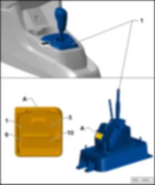
1 -  Selector lever sensors control unit -J587-
A -  10-pin connector in the selector lever sensors control unit -T10g-

   
Connector description: Selector lever sensors control unit -J587-
T10g - Function
1 - Terminal 31
2 - --
3 - --
4 - --
5 - Terminal 58d
6 - --
7 - CAN-Bus, High
8 - CAN-Bus, Low
9 - Terminal 15, Fuse 19 in fuse holder A -SA19-
10 - Terminal 30, Fuse 13 in fuse holder A -SA13-

   
Parking assist control unit -J446-
Fitting Location:
VW SPACE FOX 2013 Onboard network control unit: BFM J519 https://portal-diagnostov.com/license.html
https://portal-diagnostov.com/license.html Automotive Electricians Portal FZCO Automotive Electricians Portal FZCO
Få adgang til alle ledningsdiagrammer bilDownload PDF file
1 -  Parking assist control unit -J446-
A -  12-pin connector in the parking assist control unit -T12f-
B -  16-pin connector in the parking assist control unit -T16e-

   
Connector description: Parking assist control unit -J446-
T12f - Function - T16e - Function
1 - -- - 1 - Terminal 15, Fuse 38 in fuse holder B -SB38-
2 - Rear right parking assist sensor, centre -G205- - 2 - Rear parking assist warning buzzer -H15-
3 - Rear left parking assist sensor, centre -G204- - 3 - --
4 - Rear right parking assist sensor -G206- - 4 - --
5 - Rear left parking assist sensor -G203- - 5 - --
6 - -- - 6 - CAN-Bus, High
7 - -- - 7 - --
8 - Sensor, Mass, rear - 8 - Terminal 31
9 - -- - 9 - --
10 - -- - 10 - Rear parking assist warning buzzer -H15-
11 - Sensor, voltage, rear - 11 - --
12 - -- - 12 - --
- - -- - 13 - --
- - -- - 14 - --
- - -- - 15 - CAN-Bus, Low
- - -- - 16 - --