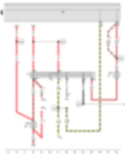
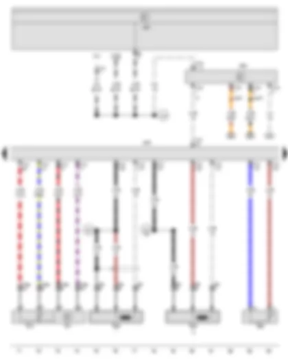
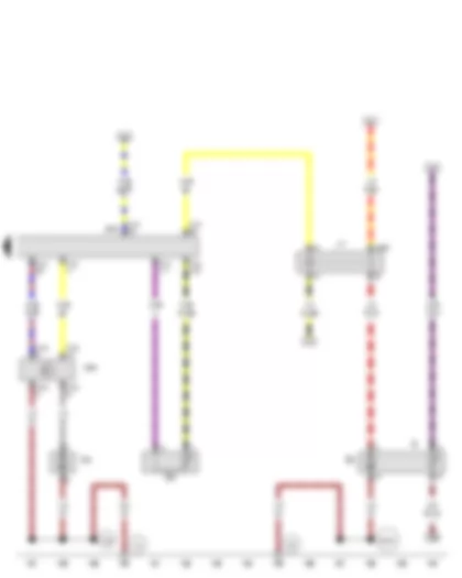
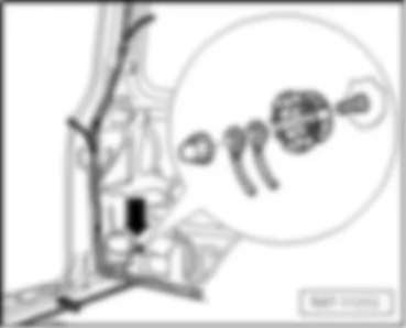
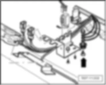
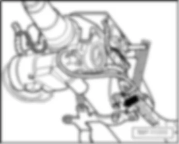
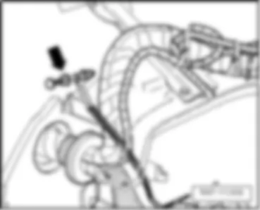
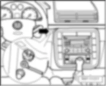
Wiring Diagram VW SHARAN 2011 - Starter - Alternator
| A | Battery |
| B | Starter |
| C | Alternator |
| C1 | Voltage regulator |
| J226 | Starter inhibitor and reversing light relay |
| J501 | Multifunction unit control unit |
| S162 | Fuse 1 (30), in battery fuse holder |
| S176 | Fuse 4 (30), in battery fuse holder |
| S177 | Fuse 5 (30), in battery fuse holder |
| T1 | Single connector, near battery |
| T14a | 14-pin connector, on left in engine compartment |
| B170 | Positive connection 2 (30), in interior wiring harness |
| B171 | Positive connection 3 (30), in interior wiring harness |
| B172 | Positive connection 4 (30), in interior wiring harness |
| B177 | Connection (61), in interior wiring harness |
| * | Only models with automatic gearbox |
| *2 | Only models with manual gearbox |
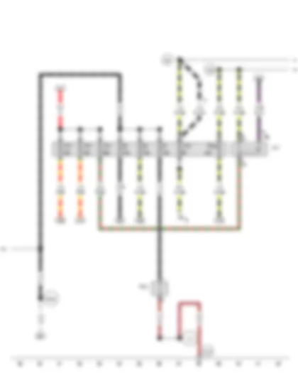
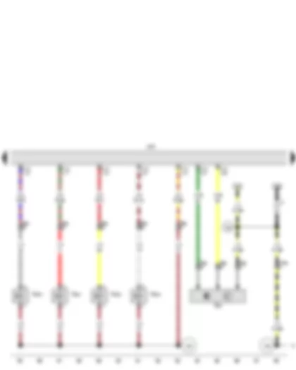
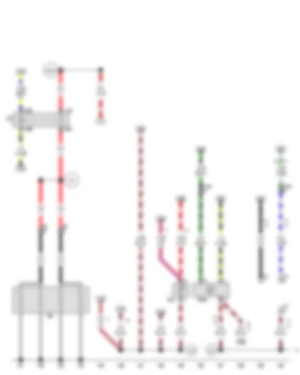
Wiring Diagram VW SHARAN 2011 - Ignition/starter switch
| D | Ignition/starter switch |
| E19 | Parking light switch |
| J59 | X-contact relief relay |
| J226 | Starter inhibitor and reversing light relay |
| J501 | Multifunction unit control unit |
| S225 | Fuse in fuse holder |
| S231 | Fuse in fuse holder |
| T12 | 12-pin connector |
| A80 | Connection 1 (X), in dash panel wiring harness |
| B158 | Connection (S), in interior wiring harness |
| B163 | Positive connection 1 (15), in interior wiring harness |
| B169 | Positive connection 1 (30), in interior wiring harness |
| B218 | Positive connection 6 (30), in interior wiring harness |
| * | Only models with manual gearbox |
| *2 | Only models with automatic gearbox |
| *3 | From May 2004 |
| *4 | Up to May 2004 |
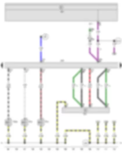
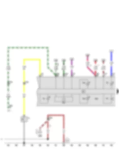
Wiring Diagram VW SHARAN 2011 - Terminal 30 voltage supply relay - Heater element for crankcase breather
| J59 | X-contact relief relay |
| J317 | Terminal 30 voltage supply relay |
| N79 | Heater element for crankcase breather |
| S1 | Fuse in relay plate fuse holder |
| S2 | Fuse in relay plate fuse holder |
| S4 | Fuse in relay plate fuse holder |
| S13 | Fuse in relay plate fuse holder |
| S14 | Fuse in relay plate fuse holder |
| S15 | Fuse in relay plate fuse holder |
| S19 | Fuse in relay plate fuse holder |
| S234 | Fuse in fuse holder |
| 131 | Earth connection 2, in engine compartment wiring harness |
| A61 | Positive connection (X), in instrument panel wiring harness |
| B163 | Positive connection 1 (15), in interior wiring harness |
| B165 | Positive connection 2 (15), in interior wiring harness |
| F25 | Connection 1, in diesel direct injection system wiring harness |
| * | From May 2004 |
| *2 | Up to May 2004 |
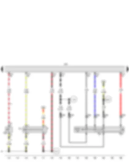
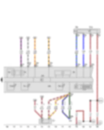
Wiring Diagram VW SHARAN 2011 - Kickdown switch - Idling speed switch - Accelerator position sender - Diesel direct injection system control unit
| A | Battery |
| F8 | Kickdown switch |
| F60 | Idling speed switch |
| G79 | Accelerator position sender |
| J248 | Diesel direct injection system control unit, on left in engine compartment |
| T6c | 6-pin connector, behind multifunction unit |
| T14a | 14-pin connector, on left in engine compartment |
| T121 | 121-pin connector |
| 85 | Earth connection 1, in engine compartment wiring harness |
| A61 | Positive connection (X), in instrument panel wiring harness |
| F25 | Connection 1, in diesel direct injection system wiring harness |
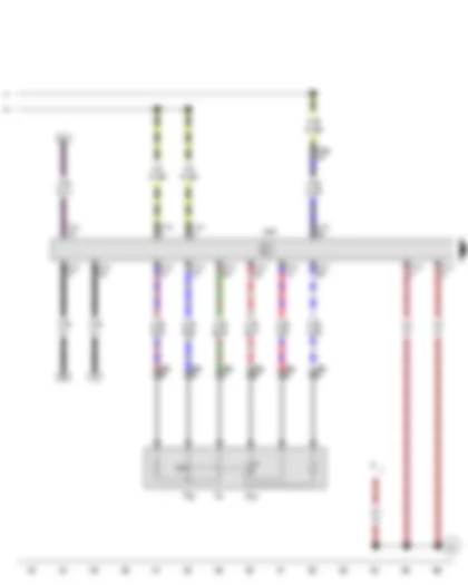
Wiring Diagram VW SHARAN 2011 - Diesel direct injection system control unit
| J104 | ABS control unit |
| J217 | Automatic gearbox control unit |
| J248 | Diesel direct injection system control unit, on left in engine compartment |
| T14b | 14-pin connector, on left in engine compartment |
| T17a | 17-pin connector, behind dash panel, left |
| T47a | 47-pin connector |
| T68a | 68-pin connector |
| T121 | 121-pin connector |
| A121 | Connection (high bus), in dash panel wiring harness |
| A122 | Connection (low bus), in dash panel wiring harness |
| D159 | Connection (high bus), in engine compartment wiring harness |
| D160 | Connection (low bus), in engine compartment wiring harness |
| * | Only models with automatic gearbox |
| *2 | Only models with ABS, EDL, TCS and ESP |
| *3 | Only models with ABS |
Wiring Diagram VW SHARAN 2011 - Engine speed sender - Coolant temperature sender - Intake manifold pressure sender - Intake manifold temperature sender - Diesel direct injection system control unit - Immobiliser control unit
| G28 | Engine speed sender |
| G62 | Coolant temperature sender |
| G71 | Intake manifold pressure sender |
| G72 | Intake manifold temperature sender |
| J248 | Diesel direct injection system control unit, on left in engine compartment |
| J362 | Immobiliser control unit |
| J501 | Multifunction unit control unit |
| T3f | 3-pin connector, on front of engine |
| T10d | 10-pin connector |
| T14a | 14-pin connector, on left in engine compartment |
| T16 | 16-pin connector |
| T121 | 121-pin connector |
| U31 | Diagnostic connection |
| A76 | Connection (K-diagnosis wire), in dash panel wiring harness |
| F27 | Connection (screening), in diesel direct injection wiring harness |
| * | Up to November 2005 |
| *2 | From November 2005 |
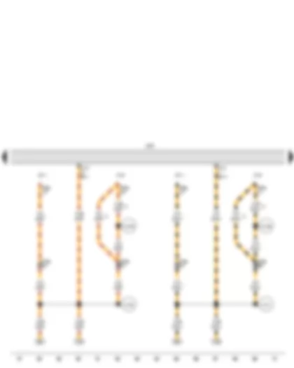
Wiring Diagram VW SHARAN 2011 - Hall sender - Diesel direct injection system control unit - Unit injector valve - No. 1 cyl. - Unit injector valve - No. 2 cyl. - Unit injector valve - No. 3 cyl. - Unit injector valve - No. 4 cyl.
| G40 | Hall sender |
| J248 | Diesel direct injection system control unit, on left in engine compartment |
| N240 | Unit injector valve, No. 1 cyl. |
| N241 | Unit injector valve, No. 2 cyl. |
| N242 | Unit injector valve, No. 3 cyl. |
| N243 | Unit injector valve, No. 4 cyl. |
| T3g | 3-pin connector, on front of engine |
| T8c | 8-pin connector, on left in engine compartment |
| T14a | 14-pin connector, on left in engine compartment |
| T121 | 121-pin connector |
| 250 | Earth connection, in diesel engine prewiring harness |
| F26 | Connection 2, in diesel direct injection system wiring harness |
| F28 | Connection 3, in diesel direct injection system wiring harness |
| * | Only models with manual gearbox |
| *2 | Up to April 2003 |
Wiring Diagram VW SHARAN 2011 - Air mass meter - Diesel direct injection system control unit - Exhaust gas recirculation valve - Charge pressure control solenoid valve - Variable intake manifold flap changeover valve
| G70 | Air mass meter |
| J217 | Automatic gearbox control unit |
| J248 | Diesel direct injection system control unit, on left in engine compartment |
| J501 | Multifunction unit control unit |
| N18 | Exhaust gas recirculation valve |
| N75 | Charge pressure control solenoid valve |
| N239 | Variable intake manifold flap changeover valve |
| T5 | 5-pin connector |
| T14b | 14-pin connector, on left in engine compartment |
| T68a | 68-pin connector |
| T121 | 121-pin connector |
| B178 | Connection (speed signal), in interior wiring harness |
| D61 | Connection (air conditioning system), in engine compartment wiring harness |
| D95 | Connection (injectors), in engine compartment wiring harness |
| F26 | Connection 2, in diesel direct injection system wiring harness |
| * | Only models with automatic gearbox |
| *2 | see applicable current flow diagram for air conditioning |
| *3 | Up to October 2003 |
| *4 | From November 2003 |
| *5 | Only models with manual gearbox |
Wiring Diagram VW SHARAN 2011 - Cruise control system switch - Brake light switch - Clutch pedal switch - Brake pedal switch - Diesel direct injection system control unit
| E45 | Cruise control system switch |
| E227 | Cruise control system (CCS) SET button |
| F | Brake light switch |
| F36 | Clutch pedal switch |
| F47 | Brake pedal switch |
| J248 | Diesel direct injection system control unit, on left in engine compartment |
| T4t | 4-pin connector |
| T10s | 10-pin connector, next to steering column |
| T121 | 121-pin connector |
| A16 | Connection (CCS), in dash panel wiring harness |
| B157 | Positive connection 3 (15a), in interior wiring harness |
| D73 | Positive connection (54), in engine compartment wiring harness |
| D95 | Connection (injectors), in engine compartment wiring harness |
| * | Only models with cruise control system (CCS) |
| *2 | Only models with manual gearbox |
Wiring Diagram VW SHARAN 2011 - Fuel gauge sender - Fuel system pressurisation pump - Fuel temperature sender - Fuel pump relay - Diesel direct injection system control unit - Coolant circulation pump
| G | Fuel gauge sender |
| G6 | Fuel system pressurisation pump |
| G81 | Fuel temperature sender |
| J17 | Fuel pump relay |
| J248 | Diesel direct injection system control unit, on left in engine compartment |
| J293 | Radiator fan control unit |
| T10c | 10-pin connector |
| T121 | 121-pin connector |
| V50 | Coolant circulation pump |
| 193 | Earth connection 1, in coolant fan wiring harness |
| B104 | Connection (negative, front right speaker), in main wiring harness |
Wiring Diagram VW SHARAN 2011 - Coolant shortage indicator sender - Oil level and oil temperature sender - Glow plug relay - Engine glow plug
| G32 | Coolant shortage indicator sender |
| G266 | Oil level and oil temperature sender |
| J52 | Glow plug relay |
| Q6 | Engine glow plug |
| T2 | 2-pin connector, on left in engine compartment |
| T3f | 3-pin connector, on fuse holder, battery |
| T14a | 14-pin connector, on left in engine compartment |
| 316 | Earth connection (sender earth 2) in engine wiring harness |
| 327 | Earth connection (sender earth), in engine compartment wiring harness |
| B188 | Positive connection 5 (30), in interior wiring harness |
| F31 | Connection (engine glow plugs) in diesel direct injection system wiring harness |
| * | From May 2003 |
| *2 | see applicable current flow diagram for gearbox |
| *3 | see applicable current flow diagram for automatic gearbox |
| *4 | Only models with manual gearbox |
| *5 | Up to April 2003 |
| *6 | From May 2004 |
| *7 | Up to May 2004 |
Wiring Diagram VW SHARAN 2011 - Oil pressure switch - Speedometer - Buzzer and gong - Control unit in dash panel insert - Alternator warning lamp - Oil pressure warning lamp - Coolant temperature and coolant shortage warning lamp - Oil level warning lamp
| F1 | Oil pressure switch |
| G21 | Speedometer |
| H3 | Buzzer and gong |
| J217 | Automatic gearbox control unit |
| J285 | Control unit in dash panel insert |
| K2 | Alternator warning lamp |
| K3 | Oil pressure warning lamp |
| K28 | Coolant temperature and coolant shortage warning lamp |
| K38 | Oil level warning lamp |
| T14a | 14-pin connector, on left in engine compartment |
| T14b | 14-pin connector, on left in engine compartment |
| T32 | 32-pin connector |
| T32a | 32-pin connector |
| T68a | 68-pin connector |
| 327 | Earth connection (sender earth), in engine compartment wiring harness |
| * | Only models with automatic gearbox |
| *2 | Only models with manual gearbox |
| *3 | From May 2003 |
| *4 | see applicable current flow diagram for gearbox |
| *5 | see applicable current flow diagram for automatic gearbox |
| *6 | Up to April 2003 |
| *7 | From May 2004 |
| *8 | Up to May 2004 |
Wiring Diagram VW SHARAN 2011 - Fuel gauge - Coolant temperature gauge - Rev. counter - Ambient temperature sensor - Multifunction indicator - Control unit in dash panel insert - Data bus diagnostic interface - Glow period warning lamp - Cruise control system warning lamp - Reserve fuel warning lamp
| E86 | Multifunction display call-up button |
| E109 | Multifunction display memory switch |
| G1 | Fuel gauge |
| G3 | Coolant temperature gauge |
| G5 | Rev. counter |
| G17 | Ambient temperature sensor |
| J119 | Multifunction indicator |
| J255 | Climatronic control unit |
| J285 | Control unit in dash panel insert |
| J533 | Data bus diagnostic interface, in dash panel insert |
| K29 | Glow period warning lamp |
| K31 | Cruise control system warning lamp |
| K105 | Reserve fuel warning lamp |
| T6e | 6-pin connector |
| T28c | 28-pin connector |
| T32 | 32-pin connector |
| T32a | 32-pin connector |
| 354 | Earth connection 6, in dash panel wiring harness |
| B102 | Connection (negative, front left speaker), in main wiring harness |
| * | Only models with no Climatronic |
| *2 | From May 2004 |
| *3 | Only models with Climatronic |
| *4 | Up to May 2004 |
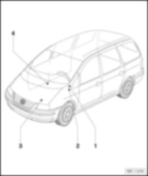
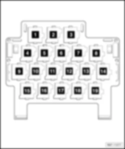
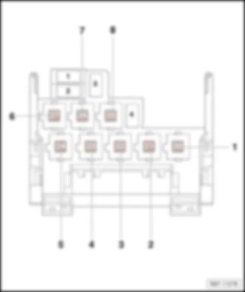
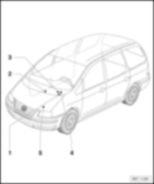
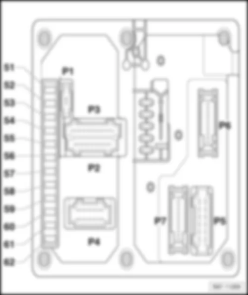
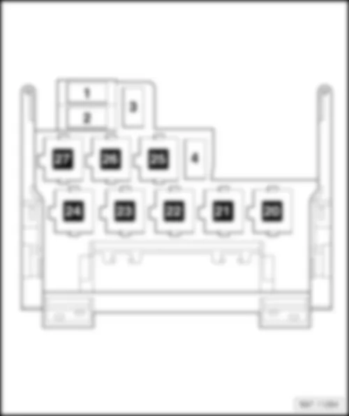
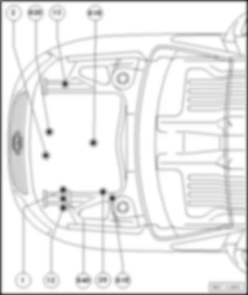
VW SHARAN 2011 Overview of relay carrier
| Upper relay carrier behind Multifunction unit |
| q | Relay assignment, from model year 2001 |
| q | Relay assignment, from model year 2002 |
| q | Relay assignment, from model year 2003 |
| q | Relay assignment, from model year 2004 |
| q | Relay assignment, from model year 2006 |
| q | Relay assignment, from model year 2009 |
| q | Relay assignment, from model year 2002 |
| q | Relay assignment, from model year 2004 |
| q | Relay assignment, from model year 2006 |
| q | Relay assignment, from model year 2009 |
| 4 - | Additional relay carrier, under seat on front right |
| q | Battery isolation relay -J7- (100) |
| Assignment of relays on upper relay carrier behind multifunction unit, from model year 2001 |
| 1 - | Folding exterior mirror control unit -J351- (361) |
| 2 - | Folding exterior mirror control unit -J351- (361) |
| 3 - | Fuel pump relay -J17- (53) |
| q | Only models with a diesel engine |
| 4 - | Seat belt warning system relay -J34- (39) |
| 5 - | Radiator fan control unit -J293- (430) |
| 6 - | Starter inhibitor and reversing light relay -J226- (175) |
| 7 - | Brake light suppression relay -J508- (444) |
| q | Models with ABS/ESP |
| 8 - | Headlight washer system relay -J39- (95) |
| 9 - | Daytime running light switch-on relay -J90- (200) |
| 10 - | Dual tone horn relay -J4- .(404) |
| 11 - | Temperature switch relay for auxiliary heater -J586- (404) |
| q | Only auxiliary heater |
| 12 - | Rear left vent window relay -J577- (404) |
| 13 - | Rear right vent window relay -J578- (404) |
| 14 - | Not assigned |
| 15 - | Fresh air blower relay, 2nd speed -J486- (404) |
| q | Models with supplementary coolant heater |
| 16 - | Not assigned |
| 17 - | Auxiliary heater operation relay -J485- (404) |
| q | Models with supplementary coolant heater |
| 18 - | Radiator fan 2nd speed relay -J101- (361) |
| 19 - | Heated exterior mirror relay -J99- (404) |
| Assignment of relays on upper relay carrier behind multifunction unit, from model year 2002 |
| 1 - | Folding exterior mirror control unit -J351- (361) |
| 2 - | Folding exterior mirror control unit -J351- (361) |
| 3 - | Fuel pump relay -J17- (53) |
| q | Only models with a diesel engine |
| 4 - | Brake light suppression relay -J508- (444) |
| q | Models with ABS/ESP |
| 5 - | Headlight washer system relay -J39- (95) |
| 6 - | Starter inhibitor and reversing light relay -J226- (175) |
| 7 - | Multifunction steering wheel control unit -J453- (451/452)1 |
| q | 1 Depends on equipment |
| 8 - | Multifunction steering wheel control unit -J453- (451/452)1 |
| q | 1 Depends on equipment |
| 9 - | Daytime running light switch-on relay -J90- (200) |
| 10 - | Dual tone horn relay -J4- .(404) / Auxiliary heater temperature switch relay -J586- |
| 11 - | Rear right vent window relay -J578- (404) |
| 12 - | Not assigned |
| 13 - | Fresh air blower relay, 2nd speed -J486- (404) |
| q | Models with supplementary coolant heater |
| 14 - | Not assigned |
| 15 - | Washer pump relay -J576- (96) |
| 16 - | Rear vent window relay -J385- (149) |
| 17 - | Auxiliary heater operation relay -J485- (404) |
| q | Models with supplementary coolant heater |
| 18 - | Radiator fan 2nd speed relay -J101- (361) / Heated exterior mirror relay -J99- (404) |
| 19 - | Heated exterior mirror relay -J99- (404) |
| Assignment of relays on upper relay carrier behind multifunction unit, from model year 2003 |
| 1 - | Folding exterior mirror control unit -J351- (361) |
| 2 - | Folding exterior mirror control unit -J351- (361) |
| 3 - | Fuel pump relay -J17- (53) |
| q | Only models with a diesel engine |
| 4 - | Brake light suppression relay -J508- (444) |
| q | Models with ABS/ESP |
| 5 - | Headlight washer system relay -J39- (95) |
| 6 - | Starter inhibitor and reversing light relay -J226- (175) |
| 7 - | Multifunction steering wheel control unit -J453- (451/452)1 |
| q | 1 Depends on equipment |
| 8 - | Multifunction steering wheel control unit -J453- (451/452)1 |
| q | 1 Depends on equipment |
| 9 - | Daytime running light switch-on relay -J90- (200) |
| 10 - | Dual tone horn relay -J4- .(404) / Auxiliary heater temperature switch relay -J586- |
| 11 - | Rear left vent window relay -J577-Rear right vent window relay -J578- (404) |
| 12 - | Not assigned |
| 13 - | Fresh air blower relay, 2nd speed -J486- (404) / Radiator fan 2nd speed relay -J101- (361) |
| q | Models with supplementary coolant heater |
| 14 - | Not assigned |
| 15 - | Washer pump relay -J576- (96) |
| 16 - | Rear vent window relay -J385- (149) |
| 17 - | Auxiliary heater operation relay -J485- .(404) / Supplementary coolant heater coolant circuit valve relay -J575- (404) |
| q | Models with supplementary coolant heater |
| 18 - | Radiator fan control unit -J293- (430) / Heated exterior mirror relay -J99- (404) |
| 19 - | Seat belt warning system relay -J34- (39) |
| Assignment of relays on upper relay carrier behind multifunction unit, from model year 2004 |
| 1 - | Folding exterior mirror control unit -J351- (361) |
| 2 - | Folding exterior mirror control unit -J351- (361) |
| 3 - | Fuel pump relay -J17- (53) |
| q | Only models with a diesel engine |
| 4 - | Radiator fan control unit -J293- (454) |
| q | Only models with engine code ASZ |
| 5 - | Radiator fan control unit -J293- (454) |
| q | Not engine code ASZ |
| 6 - | Starter inhibitor and reversing light relay -J226- (175) |
| 7 - | Multifunction steering wheel control unit -J453- (451/452)1 |
| q | 1 Depends on equipment |
| 8 - | Multifunction steering wheel control unit -J453- (451/452)1 |
| q | 1 Depends on equipment |
| 9 - | Daytime running light switch-on relay -J90- (200) |
| 10 - | Dual tone horn relay -J4- (404) / Auxiliary heater temperature switch relay -J586- |
| 11 - | Rear left vent window relay -J577-Rear right vent window relay -J578- (404) |
| 12 - | Not assigned |
| 13 - | Fresh air blower relay, 2nd speed -J486- (404) / Radiator fan 2nd speed relay -J101- (361) |
| q | Models with supplementary coolant heater |
| 14 - | Not assigned |
| 15 - | Dipped headlight control unit, on/off (Coming home system) -J665- (456) |
| 16 - | Rear vent window relay -J385- (149) |
| 17 - | Auxiliary heater operation relay -J485- .(404) / Supplementary coolant heater coolant circuit valve relay -J575- (404) |
| q | Models with supplementary coolant heater |
| 18 - | Heated exterior mirror relay -J99- (404) |
| 19 - | Headlight washer system relay -J39- (95) |
| Assignment of relays on upper relay carrier behind multifunction unit, from model year 2006 |
| 1 - | Folding exterior mirror control unit -J351- (361) |
| 2 - | Folding exterior mirror control unit -J351- (361) |
| 3 - | Fuel pump relay -J17- (53) |
| q | Only models with a diesel engine |
| 4 - | Radiator fan control unit -J293- (454) |
| q | Only models with engine codes ASZ, BRT, BHV |
| q | Fitting location depends on equipment installed, additional relay carrier below fuse holder near front battery |
| 5 - | Radiator fan control unit -J293- (454) |
| q | Not engine codes ASZ, BRT, BHV |
| 6 - | Starter inhibitor and reversing light relay -J226- (175) |
| 7 - | Multifunction steering wheel control unit -J453- (451/452)1 |
| q | 1 Depends on equipment |
| 8 - | Multifunction steering wheel control unit -J453- (451/452)1 |
| q | 1 Depends on equipment |
| 9 - | Daytime running light switch-on relay -J90- (200) |
| 10 - | Dual tone horn relay -J4- .(404) / Auxiliary heater temperature switch relay -J586- |
| 11 - | Rear left vent window relay -J577-Rear right vent window relay -J578- (404) |
| 12 - | Not assigned |
| 13 - | Fresh air blower relay, 2nd speed -J486- (404) / Radiator fan 2nd speed relay -J101- (361) |
| q | Models with supplementary coolant heater |
| q | 13/2 Continued coolant circulation relay -J151- (449) |
| 14 - | Not assigned |
| 15 - | Dipped headlight control unit, on/off (Coming home system) -J665- (456) |
| 16 - | Rear vent window relay -J385- (149) |
| 17 - | Auxiliary heater operation relay -J485- .(404) / Supplementary coolant heater coolant circuit valve relay -J575- (404) |
| q | Models with supplementary coolant heater |
| 18 - | Heated exterior mirror relay -J99- (404) |
| 19 - | Headlight washer system relay -J39- (95) |
| Assignment of relays on upper relay carrier behind multifunction unit, from model year 2009 |
| 1 - | Folding exterior mirror control unit -J351- (361) |
| 2 - | Folding exterior mirror control unit -J351- (361) |
| 3 - | Fuel pump relay -J17- (53) |
| q | Only models with a diesel engine |
| 4 - | Radiator fan control unit -J293- (454) |
| q | Only models with engine codes ASZ, BRT, BHV |
| q | Fitting location depends on equipment installed, additional relay carrier below fuse holder near front battery |
| 5 - | Radiator fan control unit -J293- (454) |
| q | Not engine codes ASZ, BRT, BHV |
| 6 - | Starter inhibitor and reversing light relay -J226- (175) |
| 7 - | Multifunction steering wheel control unit -J453- (451/452)1 |
| q | 1 Depends on equipment |
| 8 - | Multifunction steering wheel control unit -J453- (451/452)1 |
| q | 1 Depends on equipment |
| 9 - | Daytime running light switch-on relay -J90- (200) |
| 10 - | Dual tone horn relay -J4- .(404) / Auxiliary heater temperature switch relay -J586- |
| 11 - | Rear left vent window relay -J577-Rear right vent window relay -J578- (404) |
| 12 - | Not assigned |
| 13 - | Fresh air blower relay, 2nd speed -J486- (404) / Radiator fan 2nd speed relay -J101- (361) |
| q | Models with supplementary coolant heater |
| q | 13/2 Continued coolant circulation relay -J151- (449) |
| 14 - | Not assigned |
| 15 - | Washer pump relay -J576- (96) |
| 16 - | Rear vent window relay -J385- (149) |
| 17 - | Auxiliary heater operation relay -J485- .(404) / Supplementary coolant heater coolant circuit valve relay -J575- (404) |
| q | Models with supplementary coolant heater |
| 18 - | Heated exterior mirror relay -J99- (404) |
| 19 - | Headlight washer system relay -J39- (95) |
| Assignment of relays on lower relay carrier behind multifunction unit, from model year 2001 |
| 1 - | Auxiliary heater operation relay -J485- (404) |
| q | Models with supplementary coolant heater |
| 2 - | Radiator fan 2nd speed relay -J101- (361) |
| 3 - | Heated exterior mirror relay -J99- (404) |
| 4 - | Release relay for terminal 61 -J574- (98) |
| 5 - | Blower relay -J323- (53) |
| q | Models with supplementary coolant heater |
| 6 - | Fuel pump relay -J17- (410) |
| q | Models with a petrol engine |
| 7 - | Secondary air pump relay -J299- (100) |
| q | Models with a petrol engine |
| 8 - | Not assigned |
Note
| t | Illustrated is a left-hand drive model. |
| t | Right-hand drive models are basically a mirror image. |
| Assignment of relays on lower relay carrier behind multifunction unit, from model year 2002 |
| 1 - | Blower relay -J323- (53) |
| q | Models with supplementary coolant heater |
| 2 - | Fuel pump relay -J17- (53) |
| q | Models with a petrol engine |
| 3 - | Secondary air pump relay -J299- (100) / Terminal 30 voltage supply relay -J317- (109) |
| 4 - | Heated windscreen relay for left side -J410- (100) |
| 5 - | Glow plug relay -J52- (103) |
| 6 - | Not assigned |
| 7 - | X-contact relief relay -J59- (100) |
| 8 - | Not assigned |
Note
| t | Illustrated is a left-hand drive model. |
| t | Right-hand drive models are basically a mirror image. |
| Assignment of relays on lower relay carrier behind multifunction unit, from model year 2004 |
| 1 - | Blower relay -J323- (53) |
| q | Models with supplementary coolant heater |
| 2 - | Fuel pump relay -J17- (53) |
| q | Models with a petrol engine |
| 3 - | Secondary air pump relay -J299- (100) / Terminal 30 voltage supply relay -J317- (109) |
| 4 - | Heated windscreen relay for left side -J410- (100) |
| 5 - | Glow plug relay -J52- (103) |
| 6 - | Not assigned |
| 7 - | X-contact relief relay -J59- (100) |
| 8 - | Not assigned |
Note
| t | Illustrated is a left-hand drive model. |
| t | Right-hand drive models are basically a mirror image. |
| Assignment of relays on lower relay carrier behind multifunction unit, from model year 2006 |
| 1 - | Blower relay -J323- (53) |
| q | Models with supplementary coolant heater |
| 2 - | Fuel pump relay -J17- (53) |
| q | Models with a petrol engine |
| 3 - | Secondary air pump relay -J299- (100) / Terminal 30 voltage supply relay -J317- (109) |
| 4 - | Heated windscreen relay for left side -J410- (100) |
| 5 - | Glow plug relay -J52- (103) |
| q | Not diesel engines with engine codes BRT, BVH |
| 6 - | Washer pump relay -J576- (96) |
| 7 - | X-contact relief relay -J59- (100) |
| 8 - | Brake light suppression relay -J508- - (444) |
| q | Models with ABS/EDL |
Note
| t | Illustrated is a left-hand drive model. |
| t | Right-hand drive models are basically a mirror image. |
| Assignment of relays on lower relay carrier behind multifunction unit, from model year 2009 |
| 1 - | Blower relay -J323- (53) |
| q | Models with supplementary coolant heater |
| 2 - | Fuel pump relay -J17- (53) |
| q | Models with a petrol engine |
| 3 - | Secondary air pump relay -J299- (100) / Terminal 30 voltage supply relay -J317- (109) |
| 4 - | Heated windscreen relay for left side -J410- (100) |
| 5 - | Glow plug relay -J52- (103) |
| q | Not diesel engines with engine codes BRT, BVH |
| 6 - | Washer pump relay -J576- (96) / Brake light suppression relay -J508- - (444) |
| 7 - | X-contact relief relay -J59- (100) |
| 8 - | Motronic current supply relay -J271- (167) / Dipped headlight control unit, on/off (Coming home system) -J665- (456) |
Note
| t | Illustrated is a left-hand drive model. |
| t | Right-hand drive models are basically a mirror image. |

