AUTOMOTIVE ELECTRICIANS PORTAL - FZCO

VW SHARAN 2009 – Taxi equipment . Wiring diagrams, Pin Connector, Location

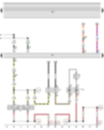
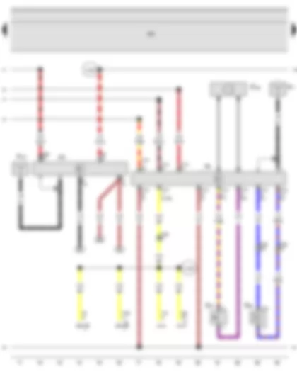
Wiring Diagram VW SHARAN 2009 - Alarm system control unit


Wiring Diagram  VW SHARAN 2009 - Alarm system control unit
E1 Light switch
E4 Headlight dipper and flasher switch
J85 Alarm system control unit, behind dash panel, right
J501 Multifunction unit control unit
T2k 2-pin connector, behind dash panel, centre
T10u 10-pin connector, behind dash panel, centre
T12 12-pin connector
T17 17-pin connector
  A95 Connection 1 (56a), in dash panel wiring harness
  B152 Connection (LTS), in interior wiring harness
  B153 Connection (RTS), in interior wiring harness
  B234 Connection (56), in interior wiring harness
*see applicable current flow diagram for basic equipment
*2Only models with daytime running lights
*3Only models with no daytime running lights

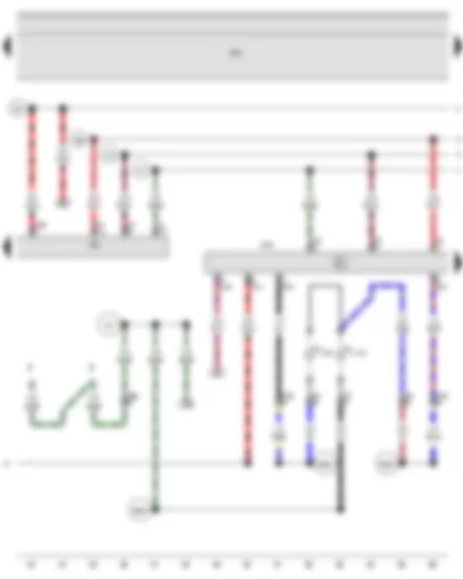
Wiring Diagram VW SHARAN 2009 - Horn plate - Horn or dual tone horn - Dual tone horn relay - Alarm system control unit


F138 Airbag coil connector and return ring with slip ring
H Horn plate
H1 Horn or dual tone horn
J4 Dual tone horn relay
J85 Alarm system control unit, behind dash panel, right
J501 Multifunction unit control unit
K65 Left turn signal warning lamp, in dash panel insert
K94 Right turn signal warning lamp, in dash panel insert
T5e 5-pin connector
T5j 5-pin connector
T10u 10-pin connector, behind dash panel, centre
T32 32-pin connector
  129 Earth connection, in dual tone horn wiring harness
  354 Earth connection 6, in dash panel wiring harness
  B102 Connection (negative, front left speaker), in main wiring harness
  B152 Connection (LTS), in interior wiring harness
  B153 Connection (RTS), in interior wiring harness
  C13 Positive connection in dual tone horn wiring harness

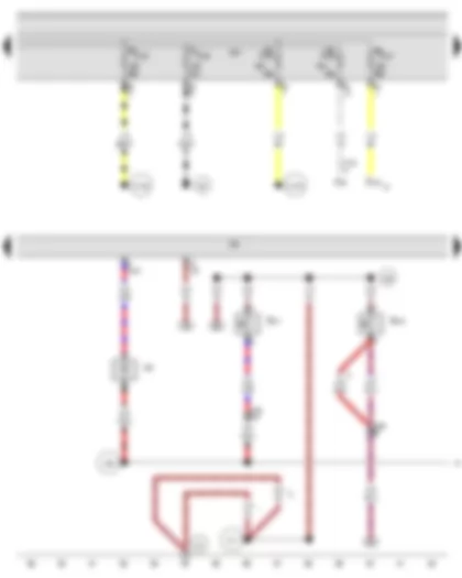
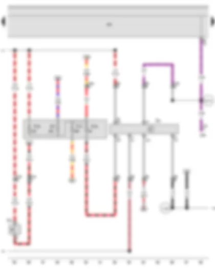
Wiring Diagram VW SHARAN 2009 - Taxi alarm system 2 switch - Alarm system off switch - Alarm system control unit


E102 Headlight range control regulator
E216 Taxi alarm system 2 switch
E217 Alarm system off switch
J29 Blocking diode, behind dash panel, right
J85 Alarm system control unit, behind dash panel, right
J501 Multifunction unit control unit
M32 Right headlight main beam bulb, on right headlight
S152 Left dipped beam fuse
S153 Right dipped beam fuse
S191 Headlight range control fuse
S192 Left main beam fuse
S193 Right main beam fuse
T10b 10-pin connector
T12l 12-pin connector, behind dash panel, centre
  239 Earth connection, in taxi alarm system wiring harness
  277 Earth connection 3, in interior wiring harness
  A51 Connection (56), in dash panel wiring harness
  D152 Positive connection 1 (56b), in engine compartment wiring harness
  D153 Positive connection 2 (56b), in engine compartment wiring harness
  X80 Connection 1, in taxi alarm system wiring harness
*From May 2004
*2Up to May 2004

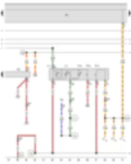
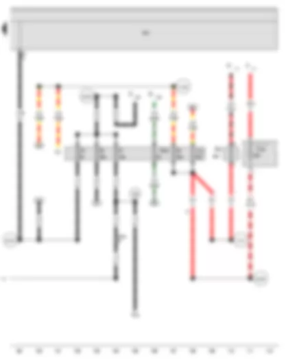
Wiring Diagram VW SHARAN 2009 - Alarm system control unit - Taxi alarm system 2 control unit - Taxi roof sign light bulb - Taxi number light bulb


J85 Alarm system control unit, behind dash panel, right
J430 Taxi alarm system 2 control unit, behind dash panel, right
J501 Multifunction unit control unit
L36 Taxi roof sign light bulb
L145 Taxi number light bulb
T3 3-pin connector, in taxi roof sign
T5a 5-pin connector, black
T12l 12-pin connector, behind dash panel, centre
X Number plate light
  A37 Connection (58a), in dash panel wiring harness
  B263 Connection (58a), in roof wiring harness
  B264 Connection 1, in roof wiring harness
  B265 Connection 2, in roof wiring harness
  X69 Connection 1, in taxi wiring harness
  X70 Connection 2, in taxi wiring harness
  X71 Connection 3, in taxi wiring harness
  X80 Connection 1, in taxi alarm system wiring harness
  X81 Connection 4, in taxi wiring harness

Wiring Diagram VW SHARAN 2009 - Interior light switch (taxi) - Taxi sign switch - Taxi alarm system 2 control unit


E20 Switch and instrument illumination regulator
E115 Interior light switch (taxi)
E138 Taxi sign switch
F3 Front passenger door contact switch
F10 Rear left door contact switch
F11 Rear right door contact switch
J430 Taxi alarm system 2 control unit, behind dash panel, right
J501 Multifunction unit control unit
K146 Roof sign warning lamp
L73 Interior light switch illumination bulb (taxi)
L74 Taxi sign switch illumination bulb
T6c 6-pin connector
T10u 10-pin connector, behind dash panel, centre
T12l 12-pin connector, behind dash panel, centre
  353 Earth connection, in taxi wiring harness
  A4 Positive connection (58b), in dash panel wiring harness
  A53 Positive connection (58b), in dash panel wiring harness
  B155 Connection 2 (DCt), in interior wiring harness
  X69 Connection 1, in taxi wiring harness
  X70 Connection 2, in taxi wiring harness
  X71 Connection 3, in taxi wiring harness
  X81 Connection 4, in taxi wiring harness
  X82 Positive connection 1 (30a), in taxi wiring harness

Wiring Diagram VW SHARAN 2009 - Two-way radio button - Taxi alarm remote control - control unit - Two-way radio - Two-way radio loudspeaker


E76 Two-way radio button
J412 Mobile telephone operating electronics control unit
J501 Multifunction unit control unit
J503 Control unit with display for radio and navigation
J601 Taxi alarm remote control, control unit
R Radio
R8 Two-way radio
R11 Aerial
R25 Two-way radio loudspeaker
R107 Remote controlled taxi alarm aerial
R122 2-way radio unit microphone
T8 8-pin connector
T10v 10-pin connector
T12l 12-pin connector
T16d 16-pin connector
T18 18-pin connector
T54 54-pin connector
  353 Earth connection, in taxi wiring harness
  A129 Connection (muting), in dash panel wiring harness
  X69 Connection 1, in taxi wiring harness
  X70 Connection 2, in taxi wiring harness
  X81 Connection 4, in taxi wiring harness
  X82 Positive connection 1 (30a), in taxi wiring harness
  X126 Positive connection 2 (30a), in taxi wiring harness
*According to equipment
*2Only models with radio Delta, RCD 200, RCD 200 MP3
*3From May 2008

Wiring Diagram VW SHARAN 2009 - Alarm system switch - Taximeter - Alarm system fuse - Taxi alarm system 2 fuse - Taximeter fuse - Taximeter and alarm system fuse


E75 Alarm system switch
G41 Taximeter
J285 Control unit in dash panel insert
J501 Multifunction unit control unit
S57 Alarm system fuse, behind dash panel, right
S181 Taxi alarm system 2 fuse, behind dash panel, right
S182 Taximeter fuse, behind dash panel, right
S183 Taximeter and alarm system fuse, behind dash panel, right
T6 6-pin connector, behind dash panel, centre
T10u 10-pin connector, behind dash panel, centre
T12l 12-pin connector, behind dash panel, centre
T32 32-pin connector
  353 Earth connection, in taxi wiring harness
  B178 Connection (speed signal), in interior wiring harness
  X126 Positive connection 2 (30a), in taxi wiring harness
  X129 Positive connection 1 (15), in taxi wiring harness

Wiring Diagram VW SHARAN 2009 - Fuse in relay plate fuse holder - Fuse in relay plate fuse holder - Fuse in relay plate fuse holder - Fuse in relay plate fuse holder - Fuse in relay plate fuse holder - 2nd battery fuse - Fuse 1 (30) - in battery fuse holder - Fuse in fuse holder


A Battery
A1 Second battery
D Ignition/starter switch
E1 Light switch
J501 Multifunction unit control unit
N79 Heater element for crankcase breather
S1 Fuse in relay plate fuse holder
S3 Fuse in relay plate fuse holder
S6 Fuse in relay plate fuse holder
S8 Fuse in relay plate fuse holder
S10 Fuse in relay plate fuse holder
S65 2nd battery fuse, under front passenger seat
S162 Fuse 1 (30), in battery fuse holder
S228 Fuse in fuse holder
T10u 10-pin connector, behind dash panel, centre
U5 12 V socket, on left in luggage compartment
  B135 Connection 1 (15a), in interior wiring harness
  B163 Positive connection 1 (15), in interior wiring harness
  B188 Positive connection 5 (30), in interior wiring harness
  W47 Positive connection 2 (30a), in floor wiring harness
  X55 Positive connection (15), in optional equipment wiring harness
  X128 Positive connection 4 (30a), in taxi wiring harness
  X129 Positive connection 1 (15), in taxi wiring harness
*Only models with second battery
*2Only models with no second battery


VW SHARAN 2009 Overview of relay carrier

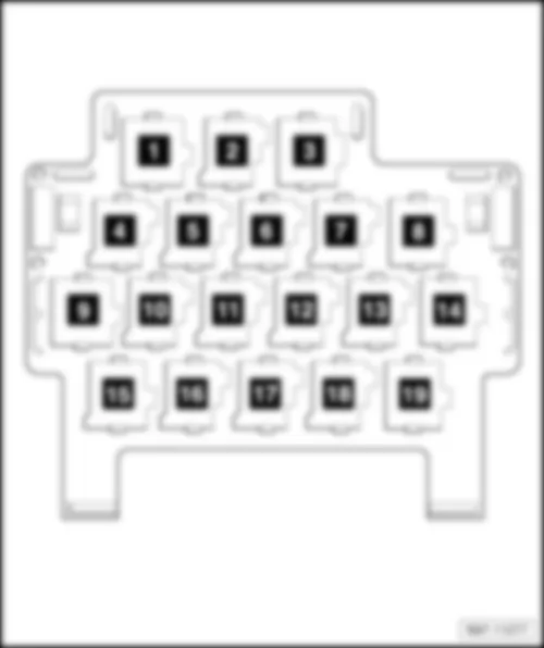
Overview of relay carrier
Upper relay carrier behind Multifunction unit
q   Relay assignment, from model year 2001
q   Relay assignment, from model year 2002
q   Relay assignment, from model year 2003
q   Relay assignment, from model year 2004
q   Relay assignment, from model year 2006
q   Relay assignment, from model year 2009
q   Relay assignment, from model year 2002
q   Relay assignment, from model year 2004
q   Relay assignment, from model year 2006
q   Relay assignment, from model year 2009
4 -  Additional relay carrier, under seat on front right
q   Battery isolation relay -J7- (100)

   
Assignment of relays on upper relay carrier behind multifunction unit, from model year 2001
1 -  Folding exterior mirror control unit -J351- (361)
2 -  Folding exterior mirror control unit -J351- (361)
3 -  Fuel pump relay -J17- (53)
q   Only models with a diesel engine
4 -  Seat belt warning system relay -J34- (39)
5 -  Radiator fan control unit -J293- (430)
6 -  Starter inhibitor and reversing light relay -J226- (175)
7 -  Brake light suppression relay -J508- (444)
q   Models with ABS/ESP
8 -  Headlight washer system relay -J39- (95)
9 -  Daytime running light switch-on relay -J90- (200)
10 -  Dual tone horn relay -J4- .(404)
11 -  Temperature switch relay for auxiliary heater -J586- (404)
q   Only auxiliary heater
12 -  Rear left vent window relay -J577- (404)
13 -  Rear right vent window relay -J578- (404)
14 -  Not assigned
15 -  Fresh air blower relay, 2nd speed -J486- (404)
q   Models with supplementary coolant heater
16 -  Not assigned
17 -  Auxiliary heater operation relay -J485- (404)
q   Models with supplementary coolant heater
18 -  Radiator fan 2nd speed relay -J101- (361)
19 -  Heated exterior mirror relay -J99- (404)


VW SHARAN 2009 Assignment of relays on upper relay carrier behind multifunction unit, from model year 2002

Assignment of relays on upper relay carrier behind multifunction unit, from model year 2002
1 -  Folding exterior mirror control unit -J351- (361)
2 -  Folding exterior mirror control unit -J351- (361)
3 -  Fuel pump relay -J17- (53)
q   Only models with a diesel engine
4 -  Brake light suppression relay -J508- (444)
q   Models with ABS/ESP
5 -  Headlight washer system relay -J39- (95)
6 -  Starter inhibitor and reversing light relay -J226- (175)
7 -  Multifunction steering wheel control unit -J453- (451/452)1
q   1 Depends on equipment
8 -  Multifunction steering wheel control unit -J453- (451/452)1
q   1 Depends on equipment
9 -  Daytime running light switch-on relay -J90- (200)
10 -  Dual tone horn relay -J4- .(404) / Auxiliary heater temperature switch relay -J586-
11 -  Rear right vent window relay -J578- (404)
12 -  Not assigned
13 -  Fresh air blower relay, 2nd speed -J486- (404)
q   Models with supplementary coolant heater
14 -  Not assigned
15 -  Washer pump relay -J576- (96)
16 -  Rear vent window relay -J385- (149)
17 -  Auxiliary heater operation relay -J485- (404)
q   Models with supplementary coolant heater
18 -  Radiator fan 2nd speed relay -J101- (361) / Heated exterior mirror relay -J99- (404)
19 -  Heated exterior mirror relay -J99- (404)


VW SHARAN 2009 Assignment of relays on upper relay carrier behind multifunction unit, from model year 2003

Assignment of relays on upper relay carrier behind multifunction unit, from model year 2003
1 -  Folding exterior mirror control unit -J351- (361)
2 -  Folding exterior mirror control unit -J351- (361)
3 -  Fuel pump relay -J17- (53)
q   Only models with a diesel engine
4 -  Brake light suppression relay -J508- (444)
q   Models with ABS/ESP
5 -  Headlight washer system relay -J39- (95)
6 -  Starter inhibitor and reversing light relay -J226- (175)
7 -  Multifunction steering wheel control unit -J453- (451/452)1
q   1 Depends on equipment
8 -  Multifunction steering wheel control unit -J453- (451/452)1
q   1 Depends on equipment
9 -  Daytime running light switch-on relay -J90- (200)
10 -  Dual tone horn relay -J4- .(404) / Auxiliary heater temperature switch relay -J586-
11 -  Rear left vent window relay -J577-Rear right vent window relay -J578- (404)
12 -  Not assigned
13 -  Fresh air blower relay, 2nd speed -J486- (404) / Radiator fan 2nd speed relay -J101- (361)
q   Models with supplementary coolant heater
14 -  Not assigned
15 -  Washer pump relay -J576- (96)
16 -  Rear vent window relay -J385- (149)
17 -  Auxiliary heater operation relay -J485- .(404) / Supplementary coolant heater coolant circuit valve relay -J575- (404)
q   Models with supplementary coolant heater
18 -  Radiator fan control unit -J293- (430) / Heated exterior mirror relay -J99- (404)
19 -  Seat belt warning system relay -J34- (39)


VW SHARAN 2009 Assignment of relays on upper relay carrier behind multifunction unit, from model year 2004

Assignment of relays on upper relay carrier behind multifunction unit, from model year 2004
1 -  Folding exterior mirror control unit -J351- (361)
2 -  Folding exterior mirror control unit -J351- (361)
3 -  Fuel pump relay -J17- (53)
q   Only models with a diesel engine
4 -  Radiator fan control unit -J293- (454)
q   Only models with engine code ASZ
5 -  Radiator fan control unit -J293- (454)
q   Not engine code ASZ
6 -  Starter inhibitor and reversing light relay -J226- (175)
7 -  Multifunction steering wheel control unit -J453- (451/452)1
q   1 Depends on equipment
8 -  Multifunction steering wheel control unit -J453- (451/452)1
q   1 Depends on equipment
9 -  Daytime running light switch-on relay -J90- (200)
10 -  Dual tone horn relay -J4- (404) / Auxiliary heater temperature switch relay -J586-
11 -  Rear left vent window relay -J577-Rear right vent window relay -J578- (404)
12 -  Not assigned
13 -  Fresh air blower relay, 2nd speed -J486- (404) / Radiator fan 2nd speed relay -J101- (361)
q   Models with supplementary coolant heater
14 -  Not assigned
15 -  Dipped headlight control unit, on/off (Coming home system) -J665- (456)
16 -  Rear vent window relay -J385- (149)
17 -  Auxiliary heater operation relay -J485- .(404) / Supplementary coolant heater coolant circuit valve relay -J575- (404)
q   Models with supplementary coolant heater
18 -  Heated exterior mirror relay -J99- (404)
19 -  Headlight washer system relay -J39- (95)


VW SHARAN 2009 Assignment of relays on upper relay carrier behind multifunction unit, from model year 2006

Assignment of relays on upper relay carrier behind multifunction unit, from model year 2006
1 -  Folding exterior mirror control unit -J351- (361)
2 -  Folding exterior mirror control unit -J351- (361)
3 -  Fuel pump relay -J17- (53)
q   Only models with a diesel engine
4 -  Radiator fan control unit -J293- (454)
q   Only models with engine codes ASZ, BRT, BHV
q   Fitting location depends on equipment installed, additional relay carrier below fuse holder near front battery
5 -  Radiator fan control unit -J293- (454)
q   Not engine codes ASZ, BRT, BHV
6 -  Starter inhibitor and reversing light relay -J226- (175)
7 -  Multifunction steering wheel control unit -J453- (451/452)1
q   1 Depends on equipment
8 -  Multifunction steering wheel control unit -J453- (451/452)1
q   1 Depends on equipment
9 -  Daytime running light switch-on relay -J90- (200)
10 -  Dual tone horn relay -J4- .(404) / Auxiliary heater temperature switch relay -J586-
11 -  Rear left vent window relay -J577-Rear right vent window relay -J578- (404)
12 -  Not assigned
13 -  Fresh air blower relay, 2nd speed -J486- (404) / Radiator fan 2nd speed relay -J101- (361)
q   Models with supplementary coolant heater
q   13/2 Continued coolant circulation relay -J151- (449)
14 -  Not assigned
15 -  Dipped headlight control unit, on/off (Coming home system) -J665- (456)
16 -  Rear vent window relay -J385- (149)
17 -  Auxiliary heater operation relay -J485- .(404) / Supplementary coolant heater coolant circuit valve relay -J575- (404)
q   Models with supplementary coolant heater
18 -  Heated exterior mirror relay -J99- (404)
19 -  Headlight washer system relay -J39- (95)


VW SHARAN 2009 Assignment of relays on upper relay carrier behind multifunction unit, from model year 2009

Assignment of relays on upper relay carrier behind multifunction unit, from model year 2009
1 -  Folding exterior mirror control unit -J351- (361)
2 -  Folding exterior mirror control unit -J351- (361)
3 -  Fuel pump relay -J17- (53)
q   Only models with a diesel engine
4 -  Radiator fan control unit -J293- (454)
q   Only models with engine codes ASZ, BRT, BHV
q   Fitting location depends on equipment installed, additional relay carrier below fuse holder near front battery
5 -  Radiator fan control unit -J293- (454)
q   Not engine codes ASZ, BRT, BHV
6 -  Starter inhibitor and reversing light relay -J226- (175)
7 -  Multifunction steering wheel control unit -J453- (451/452)1
q   1 Depends on equipment
8 -  Multifunction steering wheel control unit -J453- (451/452)1
q   1 Depends on equipment
9 -  Daytime running light switch-on relay -J90- (200)
10 -  Dual tone horn relay -J4- .(404) / Auxiliary heater temperature switch relay -J586-
11 -  Rear left vent window relay -J577-Rear right vent window relay -J578- (404)
12 -  Not assigned
13 -  Fresh air blower relay, 2nd speed -J486- (404) / Radiator fan 2nd speed relay -J101- (361)
q   Models with supplementary coolant heater
q   13/2 Continued coolant circulation relay -J151- (449)
14 -  Not assigned
15 -  Washer pump relay -J576- (96)
16 -  Rear vent window relay -J385- (149)
17 -  Auxiliary heater operation relay -J485- .(404) / Supplementary coolant heater coolant circuit valve relay -J575- (404)
q   Models with supplementary coolant heater
18 -  Heated exterior mirror relay -J99- (404)
19 -  Headlight washer system relay -J39- (95)


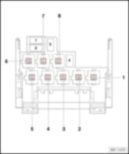
VW SHARAN 2009 Assignment of relays on lower relay carrier behind multifunction unit, from model year 2001

Assignment of relays on lower relay carrier behind multifunction unit, from model year 2001
1 -  Auxiliary heater operation relay -J485- (404)
q   Models with supplementary coolant heater
2 -  Radiator fan 2nd speed relay -J101- (361)
3 -  Heated exterior mirror relay -J99- (404)
4 -  Release relay for terminal 61 -J574- (98)
5 -  Blower relay -J323- (53)
q   Models with supplementary coolant heater
6 -  Fuel pump relay -J17- (410)
q   Models with a petrol engine
7 -  Secondary air pump relay -J299- (100)
q   Models with a petrol engine
8 -  Not assigned
  Note
t  Illustrated is a left-hand drive model.
t  Right-hand drive models are basically a mirror image.


VW SHARAN 2009 Assignment of relays on lower relay carrier behind multifunction unit, from model year 2002

Assignment of relays on lower relay carrier behind multifunction unit, from model year 2002
1 -  Blower relay -J323- (53)
q   Models with supplementary coolant heater
2 -  Fuel pump relay -J17- (53)
q   Models with a petrol engine
3 -  Secondary air pump relay -J299- (100) / Terminal 30 voltage supply relay -J317- (109)
4 -  Heated windscreen relay for left side -J410- (100)
5 -  Glow plug relay -J52- (103)
6 -  Not assigned
7 -  X-contact relief relay -J59- (100)
8 -  Not assigned
  Note
t  Illustrated is a left-hand drive model.
t  Right-hand drive models are basically a mirror image.


VW SHARAN 2009 Assignment of relays on lower relay carrier behind multifunction unit, from model year 2004

Assignment of relays on lower relay carrier behind multifunction unit, from model year 2004
1 -  Blower relay -J323- (53)
q   Models with supplementary coolant heater
2 -  Fuel pump relay -J17- (53)
q   Models with a petrol engine
3 -  Secondary air pump relay -J299- (100) / Terminal 30 voltage supply relay -J317- (109)
4 -  Heated windscreen relay for left side -J410- (100)
5 -  Glow plug relay -J52- (103)
6 -  Not assigned
7 -  X-contact relief relay -J59- (100)
8 -  Not assigned
  Note
t  Illustrated is a left-hand drive model.
t  Right-hand drive models are basically a mirror image.


VW SHARAN 2009 Assignment of relays on lower relay carrier behind multifunction unit, from model year 2006

Assignment of relays on lower relay carrier behind multifunction unit, from model year 2006
1 -  Blower relay -J323- (53)
q   Models with supplementary coolant heater
2 -  Fuel pump relay -J17- (53)
q   Models with a petrol engine
3 -  Secondary air pump relay -J299- (100) / Terminal 30 voltage supply relay -J317- (109)
4 -  Heated windscreen relay for left side -J410- (100)
5 -  Glow plug relay -J52- (103)
q   Not diesel engines with engine codes BRT, BVH
6 -  Washer pump relay -J576- (96)
7 -  X-contact relief relay -J59- (100)
8 -  Brake light suppression relay -J508- - (444)
q   Models with ABS/EDL
  Note
t  Illustrated is a left-hand drive model.
t  Right-hand drive models are basically a mirror image.


VW SHARAN 2009 Assignment of relays on lower relay carrier behind multifunction unit, from model year 2009

Assignment of relays on lower relay carrier behind multifunction unit, from model year 2009
1 -  Blower relay -J323- (53)
q   Models with supplementary coolant heater
2 -  Fuel pump relay -J17- (53)
q   Models with a petrol engine
3 -  Secondary air pump relay -J299- (100) / Terminal 30 voltage supply relay -J317- (109)
4 -  Heated windscreen relay for left side -J410- (100)
5 -  Glow plug relay -J52- (103)
q   Not diesel engines with engine codes BRT, BVH
6 -  Washer pump relay -J576- (96) / Brake light suppression relay -J508- - (444)
7 -  X-contact relief relay -J59- (100)
8 -  Motronic current supply relay -J271- (167) / Dipped headlight control unit, on/off (Coming home system) -J665- (456)
  Note
t  Illustrated is a left-hand drive model.
t  Right-hand drive models are basically a mirror image.


VW SHARAN 2009


VW SHARAN 2009 Overview of earth points in engine compartment

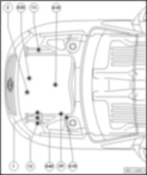
Overview of earth points in engine compartment
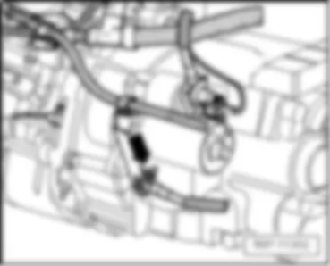
   2 Earth strap, gearbox - body
q   Torque setting: 15 Nm
q   Fitting location: Manual gearbox
q   Fitting location: Automatic gearbox
   620 Earth point, on front of engine
q   Torque setting: 15 Nm
q   Fitting location:
   13 Earth point, on right in engine compartment
q   Torque setting: 9 Nm
q   Fitting location:
   618 Earth point, on left of engine
q   Torque setting: 9 Nm
q   Fittings location
   615 Earth point, on left suspension strut
q   Torque setting: 9 Nm
q   Fitting location:
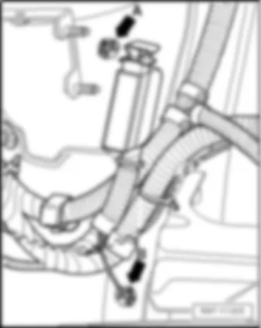
   29 Earth point, near brake servo
q   Torque setting: 9 Nm
q   Fitting location:
   640 Earth point 2, left in engine compartment
q   Torque setting: 9Nm
q   Fitting location:
   12 Earth point, on left in engine compartment
q   Torque setting: 9 Nm
q   Fitting location:
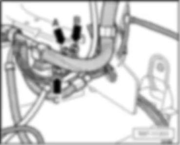
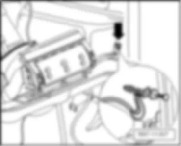
   1 Earth strap, battery - body
q   Torque setting: 20 Nm
q   Fitting location:

   
   2 Earth strap, gearbox - body, only models with a manual gearbox -arrow-
 
   2 Earth strap, gearbox - body, only models with an automatic gearbox -arrow-
 
   620 Earth point, on front of engine -arrow-
 
   13 Earth point on right in engine compartment -arrow-
 
   618 Earth point, on left on engine -arrow-
 
   615 Earth point on left suspension strut -arrow A-
 
   29 Earth point, near brake servo -arrow B-
 
   640 Earth point 2 on left in engine compartment -arrow A-
 
   12 Earth point on left in engine compartment -arrow B-
 
   1 Earth strap, battery - body -arrow C-
 
Overview of earth points in vehicle interior
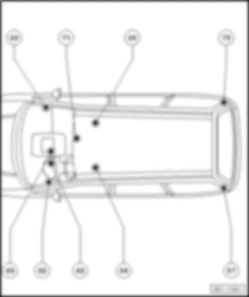
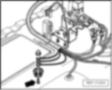
   33 Earth point, on right behind dash panel
q   Torque setting: 9 Nm
q   Fitting location:
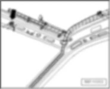
   71 Earth point, front roof rail
q   Torque setting: 9 Nm
q   Fittings location
   35 Earth point, under front passenger seat
q   Torque setting: 9 Nm
q   Fittings location
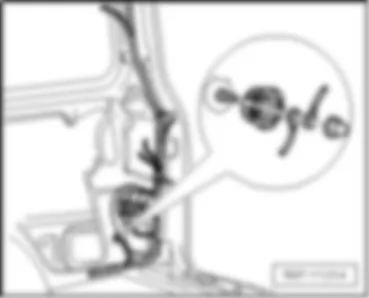
   75 Earth point, on rear right pillar
q   Torque setting: 9 Nm
q   Fittings location
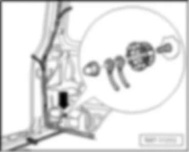
   57 Earth point, rear left pillar
q   Torque setting: 9 Nm
q   Fittings location
   34 Earth point, under driver seat
q   Torque setting: 9 Nm
q   Fittings location
   42 Earth point, next to steering column
q   Torque setting: 9 Nm
q   Fittings location
   32 Earth point, on left behind dash panel
q   Torque setting: 9 Nm
Fittings location
   45 Earth point, centre behind dash panel
q   Torque setting: 9 Nm
q   Fittings location

   
   33 Earth point, on right behind dash panel -arrow-
 
   71 Earth point, on roof rail -arrow-
 
   35 Earth point, under front passenger seat -arrow-
 
   75 Earth point, on rear right pillar -arrow-
 
   57 Earth point, on rear left pillar -arrow-
 
   34 Earth point, under driver seat -arrow-
 
   42 Earth point, next to steering column -arrow-
 
   32 Earth point, on left behind dash panel -arrow-
 
   45 Earth point, behind centre of dash panel -arrow-


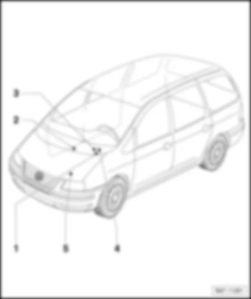
VW SHARAN 2009 Overview of fuses

Overview of fuses
Fuses in multifunction unit fuse holder
q   Fitting location
q   Fuse assignment to model year 2006
q   Fuse assignment from model year 2006
q   Fuse assignment from model year 2009
Fuses in additional fuse holder under seat on front right:
q   Fuse assignment to model year 2006
q   Fuse assignment from model year 2006
q   Fuse assignment from model year 2009
3 - 
q   Fuse assignment to model year 2006
q   Fuse assignment from model year 2006
q   Fuse assignment from model year 2009
4 -  Fuses in lower additional fuse holder of multifunction unit:
q   Fuse assignment to model year 2006
q   Fuse assignment from model year 2006
q   Fuse assignment from model year 2009
5 -  Fuses in battery fuse holder
q   Fuse assignment to model year 2006
q   Fuse assignment from model year 2006
q   Fuse assignment from model year 2009

   
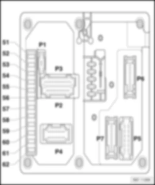
Fitting location of fuses on multifunction unit fuse holder
 -  Fuse colours
30 A -  green
25 A -  white
20 A -  yellow
15 A -  blue
10 A -  red
7,5 A -  brown
5 A -  beige
3 A -  purple

   
Fuse assignment on multifunction unit fuse holder, from model year 2006
No. Current Flow Diagram designation Nominal value   Function/component Terminal
51 - Heated rear window fuse -S41- 20 A - Heated rear window -Z1-
Heated exterior mirror relay -J99-
30a
52 - Turn signal fuse -S151- 20 A - Indicator lamp for hazard warning light -K6-
Left turn signal warning lamp -K65-
Right turn signal warning lamp -K94-
Driver side turn signal repeater bulb in exterior mirror -L131-
Front passenger side turn signal repeater bulb in exterior mirror -L132-
Front left turn signal bulb -M5-
Rear left turn signal bulb -M6-
Front right turn signal bulb -M7-
Rear right turn signal bulb -M8-
13-pin connector -T13- , Trailer socket
53 - Consumer switch-off fuse -S157- 10 A - Front interior light -W1-
Glove compartment light -W6-
Centre interior light -W7-
Rear left reading light -W11-
Rear right reading light -W12-
Front passenger side illuminated vanity mirror -W14-
Luggage compartment light on left -W18-
Driver side illuminated vanity mirror -W20-
Driver side door warning lamp -W30-
Front left entry light -W31-
Front right entry light -W32-
Rear left entry light -W33-
Rear right entry light -W34-
Right luggage compartment light -W35-
Front passenger side door warning lamp -W36-
Rear left door warning lamp -W37-
Rear right door warning lamp -W38-
Left centre reading light -W39-
Right centre reading light -W40-
Rear interior light -W43-
Rear centre reading light -W44-
 
54 - Alarm horn fuse -S158- 10 A - Alarm horn -H12-
55 - Terminal 30 voltage supply fuse -S190- 5 A - Multifunction unit control unit -J501-
30
56 - Right side light fuse -S155- 5 A - Control unit in dash panel insert -J285-
Right tail light bulb -M2-
Right side light bulb -M3-
13-pin connector -T13- , Trailer socket
58R
57 - Left side light fuse -S154- 5 A - Control unit in dash panel insert -J285-
Left tail light bulb -M4-
Left side light bulb -M1-
13-pin connector -T13- , Trailer socket
58L
58 - Headlight range control fuse -S191- 10 A - Switch and instrument illumination regulator -E20-  
59 - Left dipped beam fuse -S152- 15 A - Left headlight dipped beam bulb -M29-
Left headlight range control motor -V48-
56b
60 - Right dipped beam fuse -S153- 15 A - Right headlight dipped beam bulb -M31-
Right headlight range control motor -V49-
56b
61 - Left main beam fuse -S192- 10 A - Left headlight main beam bulb -M30-
Main beam warning lamp -K1-
56a
62 - Right main beam fuse -S193- 10 A - Right headlight main beam bulb -M32-
56a

   
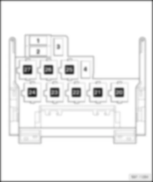
Fitting location of fuses on fuse holder under multifunction unit
 -  Fuse colours
30 A -  green
25 A -  white
20 A -  yellow
15 A -  blue
10 A -  red
7,5 A -  brown
5 A -  beige
3 A -  purple
  Note
t  Fuses from S 23 are designated with an additional 2 in the current flow diagram.
t  Example: S 40 is S 240 in the current flow diagram.

   
Fuse assignment of fuses on fuse holder under multifunction unit, to model year 2006
No. Current Flow Diagram designation Nominal value   Function/component Terminal
1 - Fuses in relay plate fuse holder -S1- 10 A


15 A
- Models with 2.0l engine:
Heater element for crankcase breather -N79- Vehicles with 2.8l engine:
Oil level and oil temperature sender -G266-
Variable intake manifold changeover valve -N156-
Camshaft control valve 1 -N205-
Exhaust camshaft control valve 1 -N318-
Heater element for crankcase breather -N79-
Models with a diesel engine and with no taxi equipment:
Heater element for crankcase breather -N79-
Models with a diesel engine and taxi equipment:
Taximeter -G41-
Heater element for crankcase breather -N79-
Taxi alarm remote control, control unit -J601-
15
2 - Fuses in relay plate fuse holder -S2- 10 A - Mirror adjustment switch -E43-
Cruise control system switch -E45-
Right vent window switch -E141-
Left vent window switch -E140-
Operating unit in steering wheel -E221-
Airbag coil connector and return ring with slip ring -F138-
Radiator fan control unit -J293-
Front left window regulator control unit -J295-
Front right window regulator control unit -J296-
Rear left window regulator control unit -J297-
Rear right window regulator control unit -J298-
Folding exterior mirror control unit -J351-
Parking aid control unit -J446-
Multifunction steering wheel control unit -J453-
Brake light suppression relay -J508-
Dipped headlight control unit, on/off (Coming home system) -J665-
15
3 - Fuses in relay plate fuse holder -S3- 5 A - Sunroof switch -E8-
Heated driver seat regulator -E94-
Heated front passenger seat regulator -E95-
TCS and ESP button -E256-
Clutch pedal switch -F36- (Only models with manual gearbox)
Brake pedal switch -F47- (Only models with a petrol engine)
Steering angle sender -G85-
Dual tone horn relay -J4-
ABS control unit -J104-
Digital clock -Y2-
Heater control unit -J162-
Climatronic control unit -J255-
Air conditioning system control unit -J301-
Multifunction unit control unit -J501-
Control unit with display for radio and navigation -J503-
Mobile telephone operating electronics control unit -J412- (from November 2006)
15
4 - Fuses in relay plate fuse holder -S4- 10 A - Diesel direct injection system control unit -J248-
Heater element for crankcase breather -N79- (Only models with 1.8 l Motronic)
Motronic control unit -J220-
15
5 - Fuses in relay plate fuse holder -S5- 15 A - Reversing light switch -F4-
Tiptronic switch -F189-
Hydraulic temperature sender -G271-
Automatic gearbox control unit -J217-
Starter inhibitor and reversing light relay -J226-
Selector lever lock solenoid -N110-
15
6 - Fuses in relay plate fuse holder -S6- 25 A - Dual tone horn relay -J4- 15
7 - Fuses in relay plate fuse holder -S7- 25 A - Cigarette lighter -U1- 30
8 - Fuses in relay plate fuse holder -S8- 15 A
30 A
- Models with no taxi equipment:
12-V socket -U5-
Models with taxi equipment:
Taximeter -G41-
12 V socket -U5-
Taxi alarm remote control, control unit -J601-
30
9 - Fuses in relay plate fuse holder -S9- 5 A
15 A
- Vehicles without seat heating:
Auxiliary coolant heater coolant circuit valve relay -J575-
Models with seat heating:
Heated driver seat control unit -J131-
Heated front passenger seat control unit -J132-
Auxiliary coolant heater coolant circuit valve relay -J575-
30
10 - Fuses in relay plate fuse holder -S10- 10 A


30 A
  Multimedia system control unit -J650-
Models with no taxi equipment:
12-V socket -U5-
Models with taxi equipment:
Alarm system fuse -S57-
Taxi alarm system 2 fuse -S181-
Taximeter fuse -S182-
Taximeter and alarm system fuse -S183-
30
11 - Fuses in relay plate fuse holder -S11- 20 A
25 A
- Vehicles without trailer socket:
Washer pump relay -J576-
Vehicles with trailer socket:
Washer pump relay -J576-
13-pin connector -T13- , trailer socket
30
12 - Fuses in relay plate fuse holder -S12- 20 A
30 A
- Heater control unit -J162- (Models with auxiliary coolant heater)
Dipped headlight control unit, on/off (Coming home system) -J665-
30
13 - Fuses in relay plate fuse holder -S13- 3 A
10 A
- Models with petrol engine:
Motronic control unit -J220-
Models with a diesel engine:
Fuel pump relay -J17-
30
14 - Fuses in relay plate fuse holder -S14- 30 A
25 A
- Models with a petrol engine:
Fuel pump relay -J17-
Models with a diesel engine:
Terminal 30 voltage supply relay -J317-
30
15 - Fuses in relay plate fuse holder -S15- 10 A - Brake light switch -F-
30
16 - Fuses in relay plate fuse holder -S16- 15 A - Radiator fan control unit -J293- 30
17 - Fuses in relay plate fuse holder -S17- 10 A - Automatic gearbox control unit -J217-
30
18 - Fuses in relay plate fuse holder -S18- 5 A - Radiator fan thermal switch -F18-
Radiator fan 2nd speed relay -J101-
30
19 - Fuses in relay plate fuse holder -S19- 5 A - Battery isolator relay -J7-
Heated rear window switch -E15-
Heated windscreen switch -E180-
Daytime running light switch-on relay -J90-
Diesel direct injection system control unit -J248-
Climatronic control unit -J255-
Blower relay -J323-
Left headlight range control unit -J567-
Right headlight range control unit -J568-
Temperature switch relay for auxiliary heater -J586-
Right headlight range control motor -V49-
Left headlight range control motor -V48-
Left washer jet heater element -Z20-
Right washer jet heater element -Z21-
x
20 - Fuses in relay plate fuse holder -S20- 15 A - Air conditioning system pressure switch -F129-
Rear window wiper motor -V12-
X
21 - Fuses in relay plate fuse holder -S21- 25 A - Climatronic control unit -J255-
Air conditioning system control unit -J301-
Rear fresh air blower -V80-
X
22 - Fuses in relay plate fuse holder -S22- 30 A - Climatronic control unit -J255-
Fresh air blower -V2-
X
23 - Fuse in fuse holder -S223- 10 A
15 A
- Vehicles without heated steering wheel:
Heated exterior mirror relay -J99-
Vehicles with heated steering wheel:
Heated exterior mirror relay -J99-
Heated steering wheel control unit -J721-
X
24 - Fuse in fuse holder -S224- 30 A - Wiper motor control unit -J400-
Windscreen wiper motor -V-
X
25 - Fuse in fuse holder -S225- 30 A - Models with manual gearbox:
Starter -B-
Models with automatic gearbox:
Starter inhibitor and reversing light relay -J226-
50b


30
26 - Fuse in fuse holder -S226- 15 A - Fog light switch -E7-
Rear fog light switch -E18-
75
27 - Fuse in fuse holder -S227- 25 A - Sliding sunroof adjustment control unit -J245-
Multifunction unit control unit -J501-
Digital clock -Y2-
30
28 - Fuse in fuse holder -S228- 3 A - Switch and instrument illumination regulator -E20-
Taxi number light bulb -L145-
Number plate light -X-
58a
29 - Fuse in fuse holder -S229- 20 A


10 A
- Models with 1.8l Motronic:
Current supply relay for Motronic -J271-
Models with 2.0l Motronic:
Current supply relay for Motronic -J271-
Models with 2.8l Motronic:
Ignition coil 1 with output stage -N70-
Ignition coil 2 with output stage -N127-
Ignition coil 3 with output stage -N291-
Ignition coil 4 with output stage -N292-
Ignition coil 5 with output stage -N323-
Ignition coil 6 with output stage -N324-
Models with engine code ASZ:
Radiator fan control unit -J293-
15
30 - Fuse in fuse holder -S230- 20 A - Control unit with display for radio and navigation -J503-
Radio -R-
Traffic information control unit -J559-
30
31 - Fuse in fuse holder -S231- 3 A - Control unit in dash panel insert -J285-
Mobile telephone operating electronics control unit -J412-
Multifunction unit control unit -J501-
Control unit with display for radio and navigation -J503-
Radio -R-
86s
32 - Fuse in fuse holder -S232- 5 A - Central locking switch on driver side -F59-
Central locking switch on driver side -F114-
Front left central locking actuator -F131-
Rear lid central locking motor -F218-
Steering angle sender -G85-
Headlight washer system relay -J39-
Control unit in dash panel insert -J285-
Climatronic control unit -J255-
Air conditioning system control unit -J301-
Heated windscreen relay for left side -J410-
Mobile telephone operating electronics control unit -J412- (to November 2006)
Multifunction steering wheel control unit -J453-
Multifunction unit control unit -J501-
Control unit with display for radio and navigation -J503-
Washer pump relay -J576-
Immobiliser warning lamp -K117-
Central locking SAFE function warning lamp -K133-
16-pin connector -T16- , self-diagnosis connection
30a
33 - Fuse in fuse holder -S233- 25 A - Heater control unit -J162-
30
34 - Fuse in fuse holder -S234- 5 A
10 A
- Models with a petrol engine:
Fuel pump relay -J17-
Models with a diesel engine:
Sender(s) and control elements for engine management
15

87

   
Fuse assignment in additional fuse holder under seat on front right, to model year 2006:
No. Current Flow Diagram designation Nominal value   Function/component Terminal
1 - Second battery fuse -S65- 40 A - Models with a second battery:
Battery isolation relay -J7-
Fuses in relay plate fuse holder -S7-
Fuses in relay plate fuse holder -S8-
Fuses in relay plate fuse holder -S9-
Fuses in relay plate fuse holder -S11-
Fuses in relay plate fuse holder -S12-
30a
2 - Auxiliary heater fuse -S126- 30 A - Vehicles with second battery:
Blower relay -J323-
Fresh air blower relay, 2nd speed -J486-
Fresh air blower -V2-
30a

   
Fuse assignment in additional fuse holder under seat on front right, from model year 2009:
No. Current Flow Diagram designation Nominal value   Function/component Terminal
1 - Second battery fuse -S65- 40 A - Models with a second battery:
Battery isolation relay -J7-
Fuses in relay plate fuse holder -S7-
Fuses in relay plate fuse holder -S8-
Fuses in relay plate fuse holder -S9-
Fuses in relay plate fuse holder -S11-
Fuses in relay plate fuse holder -S12-
Fuse in fuse holder -S233-
30a
2 - Auxiliary heater fuse -S126- 30 A - Vehicles with second battery:
Blower relay -J323-
Fresh air blower relay, 2nd speed -J486-
Fresh air blower -V2-
30a

   
Fuses in battery fuse holder, to model year 2006
Fuse colours
30 A -  green
25 A -  white
20 A -  yellow
15 A -  blue
10 A -  red
7,5 A -  brown
5 A -  beige
3 A -  purple
 
Fuses in battery fuse holder, from model year 2006
No. Current Flow Diagram designation Nominal value   Function/component Terminal
  - Fuse 1 (30), on battery fuse holder -S162- 60 A - Glow plug heating 30
  - Fuse 2 (30), on battery fuse holder -S163- 40 A - Radiator fan 30
  - Fuse 3 (30), on battery fuse holder -S164- 40 A
60 A
- Radiator fan (not for engine code ASZ)
Radiator fan (only for engine code ASZ)
30
  - Fuse 4 (30), on battery fuse holder -S176- 110 A - Interior 30
  - Fuse 5 (30), on battery fuse holder -S177- 150 A - Alternator 30
  - Fuse 6 (30), on battery fuse holder -S178- 3 A - Multifunction unit control unit 30
  - Fuse 7 (30), on battery fuse holder -S179- 30 A - ABS 30
  - Fuse 8 (30), on battery fuse holder -S180- 30 A - ABS (pump) 30

   
Fitting location of fuses on lower additional fuse holder of multifunction unit
  Note
t  The illustration shows the LHD version.
t  The layout is mirror-inverted in RHD models.
 
Fuse assignment of fuses on lower additional fuse holder of multifunction unit, from model year 2006
No. Current Flow Diagram designation Nominal value   Function/component Terminal
1 - Heated windscreen fuse -S127- 50 A - Heated windscreen relay for left side -J410-
Heated windscreen -Z2-
30
2 - Secondary air pump fuse -S130-

Auxiliary heater fuse -S126-
50 A
25 A
- Secondary air pump relay -J299-
Secondary air pump motor -V101-
Models with auxiliary heater and Coming home,
blower relay -J323-
Fresh air blower relay, 2nd speed -J486-
Fresh air blower -V2-
30
3 - Fuse 1 -S131- 10 A - Intermittent wiper switch -E22- 30
4 - Window regulator single fuse -S37- 30 A - Rear vent window relay -J385-
Rear left vent window relay -J577-
Rear right vent window relay -J578-
Front left window regulator control unit -J295-
Front right window regulator control unit -J296-
Rear left window regulator control unit -J297-
Rear right window regulator control unit -J298-


Fuse assignment of fuses on lower additional fuse holder of multifunction unit, from model year 2009
No. Current Flow Diagram designation Nominal value   Function/component Terminal
1 - Heated windscreen fuse -S127- 50 A - Heated windscreen relay for left side -J410-
Heated windscreen -Z2-
30
2 - Secondary air pump fuse -S130-

Auxiliary heater fuse -S126-
50 A
25 A
- Secondary air pump relay -J299-
Secondary air pump motor -V101-
Models with auxiliary heater and Coming home,
blower relay -J323-
Fresh air blower relay, 2nd speed -J486-
Fresh air blower -V2-
30
3 - Fuse 1 -S131- 10 A - Intermittent wiper switch -E22- 30
4 - Window regulator single fuse -S37- 30 A - Rear vent window relay -J385-
Rear left vent window relay -J577-
Rear right vent window relay -J578-
Front left window regulator control unit -J295-
Front right window regulator control unit -J296-
Rear left window regulator control unit -J297-
Rear right window regulator control unit -J298-
30