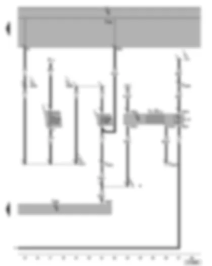
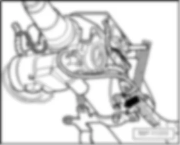
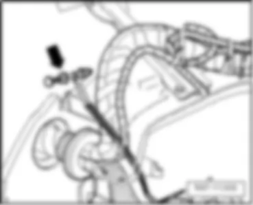
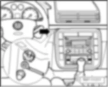
Wiring Diagram VW SHARAN 2009 - Sunroof switch - sliding sunroof adjustment control unit - sliding sunroof motor
| D | Ignition/starter switch |
| E8 | Sunroof switch |
| J245 | Sliding sunroof adjustment control unit |
| J501 | Multifunction unit control unit |
| L65 | Sliding sunroof switch illumination bulb |
| S3 | Fuse in relay plate fuse holder |
| T4 | 4-pin connector |
| T6p | 6-pin connector |
| T10t | 10-pin connector, behind A-pillar trim/ dash panel |
| V1 | Sliding sunroof motor |
| 128 | Earth connection 1, in interior light wiring harness |
| B135 | Connection 1 (15a), in interior wiring harness |
| B163 | Positive connection 1 (15), in interior wiring harness |
| B197 | Connection (closing window), in interior wiring harness |
| B207 | Connection (convenience), in interior wiring harness |
| Y3 | Positive connection (15), in instrument illumination/sliding sunroof wiring harness |
Wiring Diagram VW SHARAN 2009 - Pre-selection clock - sliding sunroof adjustment control unit - digital clock
| A | Battery |
| E111 | Preselection clock |
| J245 | Sliding sunroof adjustment control unit |
| J501 | Multifunction unit control unit |
| L75 | Digital display illumination bulb |
| S176 | Fuse 4 (30) in fuse holder on battery |
| S227 | Fuse in fuse holder |
| T5h | 5-pin connector |
| T6p | 6-pin connector |
| T10t | 10-pin connector, behind A-pillar trim/ dash panel |
| Y2 | Digital clock |
| A11 | Positive connection (58b), in dash panel wiring harness |
| B169 | Positive connection 1 (30), in interior wiring harness |
| B170 | Positive connection 2 (30), in interior wiring harness |
| B171 | Positive connection 3 (30), in interior wiring harness |
| Y1 | Positive connection (30), in interior light wiring harness |
| * | for models with auxiliary heater and electric sliding/tilting sunroof only |
VW SHARAN 2009 Overview of fuses
| Fuses in multifunction unit fuse holder |
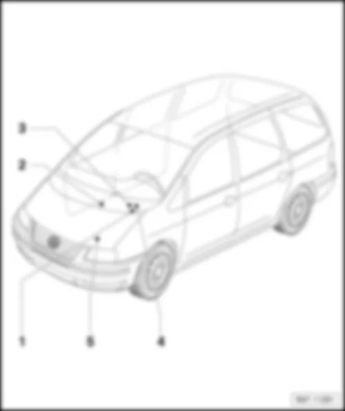
| q | Fitting location |
| q | Fuse assignment to model year 2006 |
| q | Fuse assignment from model year 2006 |
| q | Fuse assignment from model year 2009 |
| Fuses in additional fuse holder under seat on front right: |
| q | Fuse assignment to model year 2006 |
| q | Fuse assignment from model year 2006 |
| q | Fuse assignment from model year 2009 |
| 3 - |
| q | Fuse assignment to model year 2006 |
| q | Fuse assignment from model year 2006 |
| q | Fuse assignment from model year 2009 |
| 4 - | Fuses in lower additional fuse holder of multifunction unit: |
| q | Fuse assignment to model year 2006 |
| q | Fuse assignment from model year 2006 |
| q | Fuse assignment from model year 2009 |
| 5 - | Fuses in battery fuse holder |
| q | Fuse assignment to model year 2006 |
| q | Fuse assignment from model year 2006 |
| q | Fuse assignment from model year 2009 |
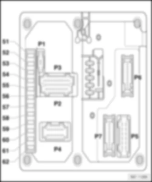
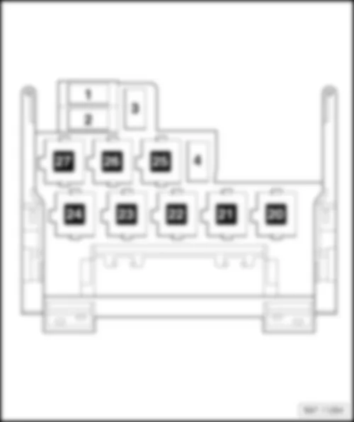
| Fitting location of fuses on multifunction unit fuse holder |
| - | Fuse colours |
| 30 A - | green |
| 25 A - | white |
| 20 A - | yellow |
| 15 A - | blue |
| 10 A - | red |
| 7,5 A - | brown |
| 5 A - | beige |
| 3 A - | purple |
| Fuse assignment on multifunction unit fuse holder, from model year 2006 |
| No. | Current Flow Diagram designation | Nominal value | Function/component | Terminal | ||
| 51 | - | Heated rear window fuse -S41- | 20 A | - | Heated rear window -Z1- Heated exterior mirror relay -J99- | 30a |
| 52 | - | Turn signal fuse -S151- | 20 A | - | Indicator lamp for hazard warning light -K6- Left turn signal warning lamp -K65- Right turn signal warning lamp -K94- Driver side turn signal repeater bulb in exterior mirror -L131- Front passenger side turn signal repeater bulb in exterior mirror -L132- Front left turn signal bulb -M5- Rear left turn signal bulb -M6- Front right turn signal bulb -M7- Rear right turn signal bulb -M8- 13-pin connector -T13- , Trailer socket | |
| 53 | - | Consumer switch-off fuse -S157- | 10 A | - | Front interior light -W1- Glove compartment light -W6- Centre interior light -W7- Rear left reading light -W11- Rear right reading light -W12- Front passenger side illuminated vanity mirror -W14- Luggage compartment light on left -W18- Driver side illuminated vanity mirror -W20- Driver side door warning lamp -W30- Front left entry light -W31- Front right entry light -W32- Rear left entry light -W33- Rear right entry light -W34- Right luggage compartment light -W35- Front passenger side door warning lamp -W36- Rear left door warning lamp -W37- Rear right door warning lamp -W38- Left centre reading light -W39- Right centre reading light -W40- Rear interior light -W43- Rear centre reading light -W44- | |
| 54 | - | Alarm horn fuse -S158- | 10 A | - | Alarm horn -H12- | |
| 55 | - | Terminal 30 voltage supply fuse -S190- | 5 A | - | Multifunction unit control unit -J501- | 30 |
| 56 | - | Right side light fuse -S155- | 5 A | - | Control unit in dash panel insert -J285- Right tail light bulb -M2- Right side light bulb -M3- 13-pin connector -T13- , Trailer socket | 58R |
| 57 | - | Left side light fuse -S154- | 5 A | - | Control unit in dash panel insert -J285- Left tail light bulb -M4- Left side light bulb -M1- 13-pin connector -T13- , Trailer socket | 58L |
| 58 | - | Headlight range control fuse -S191- | 10 A | - | Switch and instrument illumination regulator -E20- | |
| 59 | - | Left dipped beam fuse -S152- | 15 A | - | Left headlight dipped beam bulb -M29- Left headlight range control motor -V48- | 56b |
| 60 | - | Right dipped beam fuse -S153- | 15 A | - | Right headlight dipped beam bulb -M31- Right headlight range control motor -V49- | 56b |
| 61 | - | Left main beam fuse -S192- | 10 A | - | Left headlight main beam bulb -M30- Main beam warning lamp -K1- | 56a |
| 62 | - | Right main beam fuse -S193- | 10 A | - | Right headlight main beam bulb -M32- | 56a |
| Fitting location of fuses on fuse holder under multifunction unit |
| - | Fuse colours |
| 30 A - | green |
| 25 A - | white |
| 20 A - | yellow |
| 15 A - | blue |
| 10 A - | red |
| 7,5 A - | brown |
| 5 A - | beige |
| 3 A - | purple |
Note
| t | Fuses from S 23 are designated with an additional 2 in the current flow diagram. |
| t | Example: S 40 is S 240 in the current flow diagram. |
| Fuse assignment of fuses on fuse holder under multifunction unit, to model year 2006 |
| No. | Current Flow Diagram designation | Nominal value | Function/component | Terminal | ||
| 1 | - | Fuses in relay plate fuse holder -S1- | 10 A 15 A | - | Models with 2.0l engine: Heater element for crankcase breather -N79- Vehicles with 2.8l engine: Oil level and oil temperature sender -G266- Variable intake manifold changeover valve -N156- Camshaft control valve 1 -N205- Exhaust camshaft control valve 1 -N318- Heater element for crankcase breather -N79- Models with a diesel engine and with no taxi equipment: Heater element for crankcase breather -N79- Models with a diesel engine and taxi equipment: Taximeter -G41- Heater element for crankcase breather -N79- Taxi alarm remote control, control unit -J601- | 15 |
| 2 | - | Fuses in relay plate fuse holder -S2- | 10 A | - | Mirror adjustment switch -E43- Cruise control system switch -E45- Right vent window switch -E141- Left vent window switch -E140- Operating unit in steering wheel -E221- Airbag coil connector and return ring with slip ring -F138- Radiator fan control unit -J293- Front left window regulator control unit -J295- Front right window regulator control unit -J296- Rear left window regulator control unit -J297- Rear right window regulator control unit -J298- Folding exterior mirror control unit -J351- Parking aid control unit -J446- Multifunction steering wheel control unit -J453- Brake light suppression relay -J508- Dipped headlight control unit, on/off (Coming home system) -J665- | 15 |
| 3 | - | Fuses in relay plate fuse holder -S3- | 5 A | - | Sunroof switch -E8- Heated driver seat regulator -E94- Heated front passenger seat regulator -E95- TCS and ESP button -E256- Clutch pedal switch -F36- (Only models with manual gearbox) Brake pedal switch -F47- (Only models with a petrol engine) Steering angle sender -G85- Dual tone horn relay -J4- ABS control unit -J104- Digital clock -Y2- Heater control unit -J162- Climatronic control unit -J255- Air conditioning system control unit -J301- Multifunction unit control unit -J501- Control unit with display for radio and navigation -J503- Mobile telephone operating electronics control unit -J412- (from November 2006) | 15 |
| 4 | - | Fuses in relay plate fuse holder -S4- | 10 A | - | Diesel direct injection system control unit -J248- Heater element for crankcase breather -N79- (Only models with 1.8 l Motronic) Motronic control unit -J220- | 15 |
| 5 | - | Fuses in relay plate fuse holder -S5- | 15 A | - | Reversing light switch -F4- Tiptronic switch -F189- Hydraulic temperature sender -G271- Automatic gearbox control unit -J217- Starter inhibitor and reversing light relay -J226- Selector lever lock solenoid -N110- | 15 |
| 6 | - | Fuses in relay plate fuse holder -S6- | 25 A | - | Dual tone horn relay -J4- | 15 |
| 7 | - | Fuses in relay plate fuse holder -S7- | 25 A | - | Cigarette lighter -U1- | 30 |
| 8 | - | Fuses in relay plate fuse holder -S8- | 15 A 30 A | - | Models with no taxi equipment: 12-V socket -U5- Models with taxi equipment: Taximeter -G41- 12 V socket -U5- Taxi alarm remote control, control unit -J601- | 30 |
| 9 | - | Fuses in relay plate fuse holder -S9- | 5 A 15 A | - | Vehicles without seat heating: Auxiliary coolant heater coolant circuit valve relay -J575- Models with seat heating: Heated driver seat control unit -J131- Heated front passenger seat control unit -J132- Auxiliary coolant heater coolant circuit valve relay -J575- | 30 |
| 10 | - | Fuses in relay plate fuse holder -S10- | 10 A 30 A | Multimedia system control unit -J650- Models with no taxi equipment: 12-V socket -U5- Models with taxi equipment: Alarm system fuse -S57- Taxi alarm system 2 fuse -S181- Taximeter fuse -S182- Taximeter and alarm system fuse -S183- | 30 | |
| 11 | - | Fuses in relay plate fuse holder -S11- | 20 A 25 A | - | Vehicles without trailer socket: Washer pump relay -J576- Vehicles with trailer socket: Washer pump relay -J576- 13-pin connector -T13- , trailer socket | 30 |
| 12 | - | Fuses in relay plate fuse holder -S12- | 20 A 30 A | - | Heater control unit -J162- (Models with auxiliary coolant heater) Dipped headlight control unit, on/off (Coming home system) -J665- | 30 |
| 13 | - | Fuses in relay plate fuse holder -S13- | 3 A 10 A | - | Models with petrol engine: Motronic control unit -J220- Models with a diesel engine: Fuel pump relay -J17- | 30 |
| 14 | - | Fuses in relay plate fuse holder -S14- | 30 A 25 A | - | Models with a petrol engine: Fuel pump relay -J17- Models with a diesel engine: Terminal 30 voltage supply relay -J317- | 30 |
| 15 | - | Fuses in relay plate fuse holder -S15- | 10 A | - | Brake light switch -F- | 30 |
| 16 | - | Fuses in relay plate fuse holder -S16- | 15 A | - | Radiator fan control unit -J293- | 30 |
| 17 | - | Fuses in relay plate fuse holder -S17- | 10 A | - | Automatic gearbox control unit -J217- | 30 |
| 18 | - | Fuses in relay plate fuse holder -S18- | 5 A | - | Radiator fan thermal switch -F18- Radiator fan 2nd speed relay -J101- | 30 |
| 19 | - | Fuses in relay plate fuse holder -S19- | 5 A | - | Battery isolator relay -J7- Heated rear window switch -E15- Heated windscreen switch -E180- Daytime running light switch-on relay -J90- Diesel direct injection system control unit -J248- Climatronic control unit -J255- Blower relay -J323- Left headlight range control unit -J567- Right headlight range control unit -J568- Temperature switch relay for auxiliary heater -J586- Right headlight range control motor -V49- Left headlight range control motor -V48- Left washer jet heater element -Z20- Right washer jet heater element -Z21- | x |
| 20 | - | Fuses in relay plate fuse holder -S20- | 15 A | - | Air conditioning system pressure switch -F129- Rear window wiper motor -V12- | X |
| 21 | - | Fuses in relay plate fuse holder -S21- | 25 A | - | Climatronic control unit -J255- Air conditioning system control unit -J301- Rear fresh air blower -V80- | X |
| 22 | - | Fuses in relay plate fuse holder -S22- | 30 A | - | Climatronic control unit -J255- Fresh air blower -V2- | X |
| 23 | - | Fuse in fuse holder -S223- | 10 A 15 A | - | Vehicles without heated steering wheel: Heated exterior mirror relay -J99- Vehicles with heated steering wheel: Heated exterior mirror relay -J99- Heated steering wheel control unit -J721- | X |
| 24 | - | Fuse in fuse holder -S224- | 30 A | - | Wiper motor control unit -J400- Windscreen wiper motor -V- | X |
| 25 | - | Fuse in fuse holder -S225- | 30 A | - | Models with manual gearbox: Starter -B- Models with automatic gearbox: Starter inhibitor and reversing light relay -J226- | 50b 30 |
| 26 | - | Fuse in fuse holder -S226- | 15 A | - | Fog light switch -E7- Rear fog light switch -E18- | 75 |
| 27 | - | Fuse in fuse holder -S227- | 25 A | - | Sliding sunroof adjustment control unit -J245- Multifunction unit control unit -J501- Digital clock -Y2- | 30 |
| 28 | - | Fuse in fuse holder -S228- | 3 A | - | Switch and instrument illumination regulator -E20- Taxi number light bulb -L145- Number plate light -X- | 58a |
| 29 | - | Fuse in fuse holder -S229- | 20 A 10 A | - | Models with 1.8l Motronic: Current supply relay for Motronic -J271- Models with 2.0l Motronic: Current supply relay for Motronic -J271- Models with 2.8l Motronic: Ignition coil 1 with output stage -N70- Ignition coil 2 with output stage -N127- Ignition coil 3 with output stage -N291- Ignition coil 4 with output stage -N292- Ignition coil 5 with output stage -N323- Ignition coil 6 with output stage -N324- Models with engine code ASZ: Radiator fan control unit -J293- | 15 |
| 30 | - | Fuse in fuse holder -S230- | 20 A | - | Control unit with display for radio and navigation -J503- Radio -R- Traffic information control unit -J559- | 30 |
| 31 | - | Fuse in fuse holder -S231- | 3 A | - | Control unit in dash panel insert -J285- Mobile telephone operating electronics control unit -J412- Multifunction unit control unit -J501- Control unit with display for radio and navigation -J503- Radio -R- | 86s |
| 32 | - | Fuse in fuse holder -S232- | 5 A | - | Central locking switch on driver side -F59- Central locking switch on driver side -F114- Front left central locking actuator -F131- Rear lid central locking motor -F218- Steering angle sender -G85- Headlight washer system relay -J39- Control unit in dash panel insert -J285- Climatronic control unit -J255- Air conditioning system control unit -J301- Heated windscreen relay for left side -J410- Mobile telephone operating electronics control unit -J412- (to November 2006) Multifunction steering wheel control unit -J453- Multifunction unit control unit -J501- Control unit with display for radio and navigation -J503- Washer pump relay -J576- Immobiliser warning lamp -K117- Central locking SAFE function warning lamp -K133- 16-pin connector -T16- , self-diagnosis connection | 30a |
| 33 | - | Fuse in fuse holder -S233- | 25 A | - | Heater control unit -J162- | 30 |
| 34 | - | Fuse in fuse holder -S234- | 5 A 10 A | - | Models with a petrol engine: Fuel pump relay -J17- Models with a diesel engine: Sender(s) and control elements for engine management | 15 87 |
| Fuse assignment in additional fuse holder under seat on front right, to model year 2006: |
| No. | Current Flow Diagram designation | Nominal value | Function/component | Terminal | ||
| 1 | - | Second battery fuse -S65- | 40 A | - | Models with a second battery: Battery isolation relay -J7- Fuses in relay plate fuse holder -S7- Fuses in relay plate fuse holder -S8- Fuses in relay plate fuse holder -S9- Fuses in relay plate fuse holder -S11- Fuses in relay plate fuse holder -S12- | 30a |
| 2 | - | Auxiliary heater fuse -S126- | 30 A | - | Vehicles with second battery: Blower relay -J323- Fresh air blower relay, 2nd speed -J486- Fresh air blower -V2- | 30a |
| Fuse assignment in additional fuse holder under seat on front right, from model year 2009: |
| No. | Current Flow Diagram designation | Nominal value | Function/component | Terminal | ||
| 1 | - | Second battery fuse -S65- | 40 A | - | Models with a second battery: Battery isolation relay -J7- Fuses in relay plate fuse holder -S7- Fuses in relay plate fuse holder -S8- Fuses in relay plate fuse holder -S9- Fuses in relay plate fuse holder -S11- Fuses in relay plate fuse holder -S12- Fuse in fuse holder -S233- | 30a |
| 2 | - | Auxiliary heater fuse -S126- | 30 A | - | Vehicles with second battery: Blower relay -J323- Fresh air blower relay, 2nd speed -J486- Fresh air blower -V2- | 30a |
Note
|
| Fuse assignment of fuses on lower additional fuse holder of multifunction unit, from model year 2006 |
| No. | Current Flow Diagram designation | Nominal value | Function/component | Terminal | ||
| 1 | - | Heated windscreen fuse -S127- | 50 A | - | Heated windscreen relay for left side -J410- Heated windscreen -Z2- | 30 |
| 2 | - | Secondary air pump fuse -S130- Auxiliary heater fuse -S126- | 50 A 25 A | - | Secondary air pump relay -J299- Secondary air pump motor -V101- Models with auxiliary heater and Coming home, blower relay -J323- Fresh air blower relay, 2nd speed -J486- Fresh air blower -V2- | 30 |
| 3 | - | Fuse 1 -S131- | 10 A | - | Intermittent wiper switch -E22- | 30 |
| 4 | - | Window regulator single fuse -S37- | 30 A | - | Rear vent window relay -J385- Rear left vent window relay -J577- Rear right vent window relay -J578- Front left window regulator control unit -J295- Front right window regulator control unit -J296- Rear left window regulator control unit -J297- Rear right window regulator control unit -J298- |

