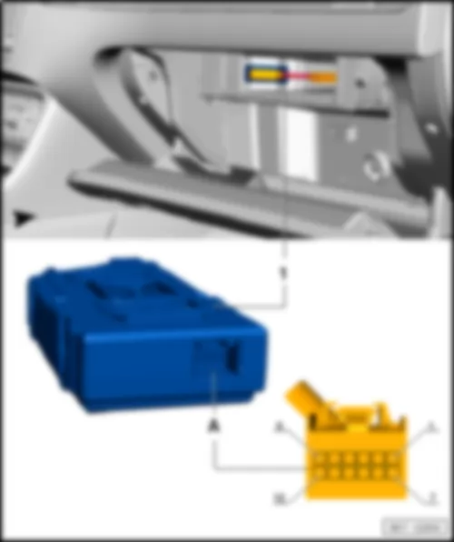
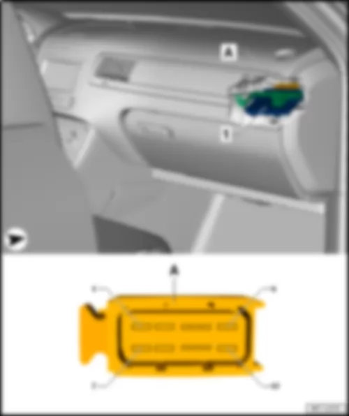
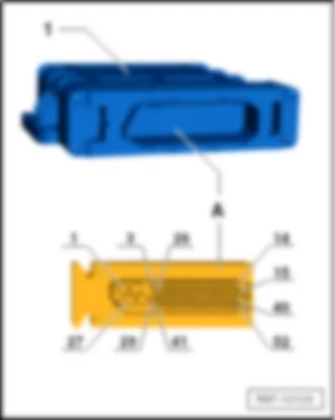
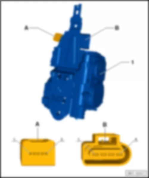
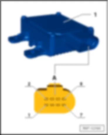
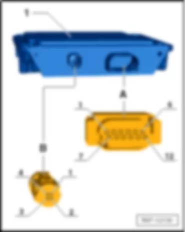
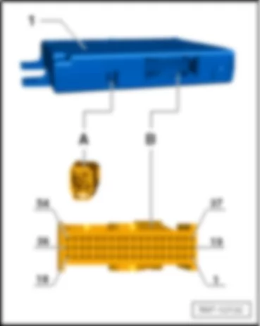
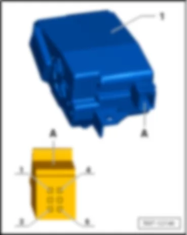
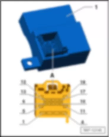
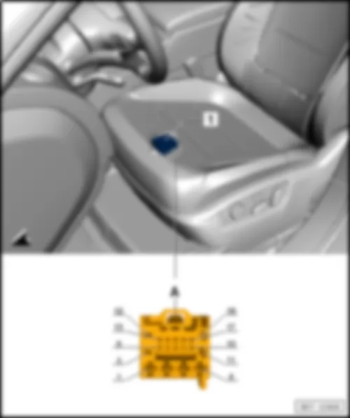
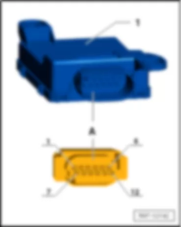
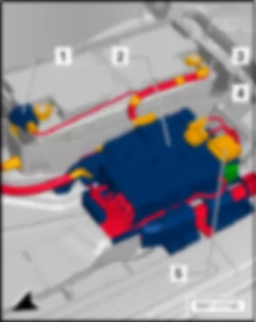
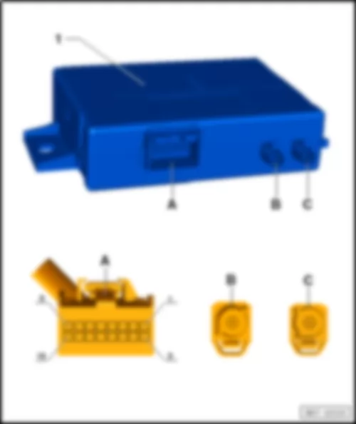
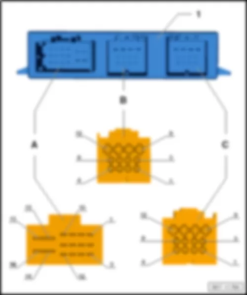
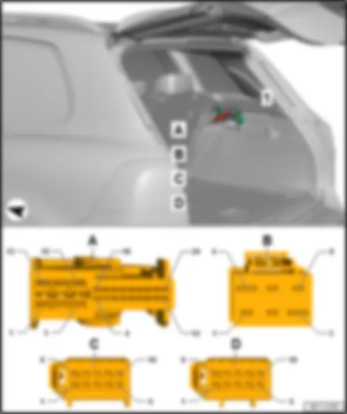
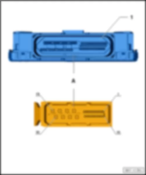
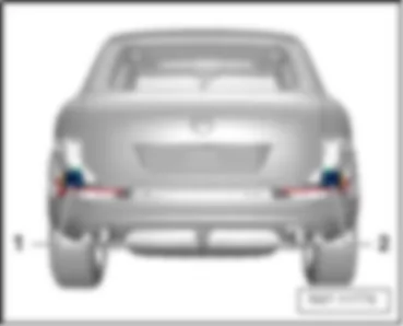
VW TOUAREG 2012 Headlight range control unit J431 |
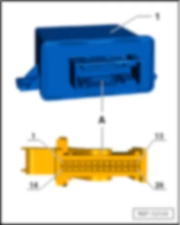
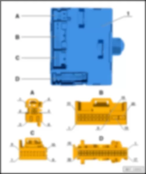
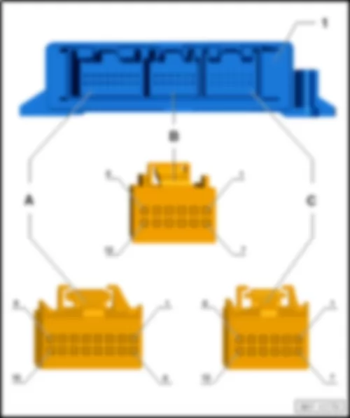
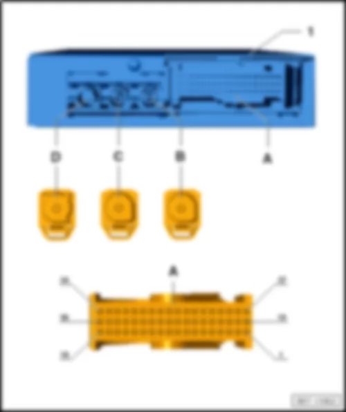
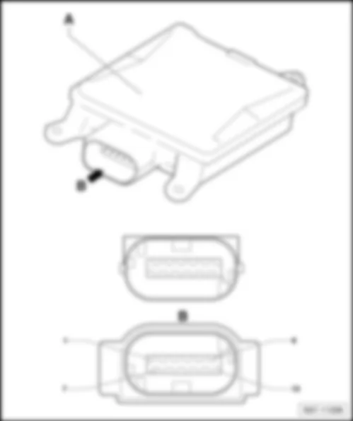
| 1 - | Headlight range control unit -J431- | | A - | 26-pin connector -T26a- | | | |
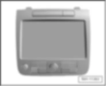
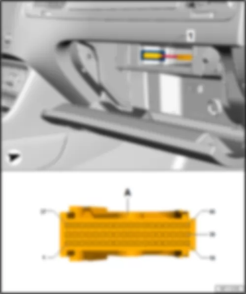
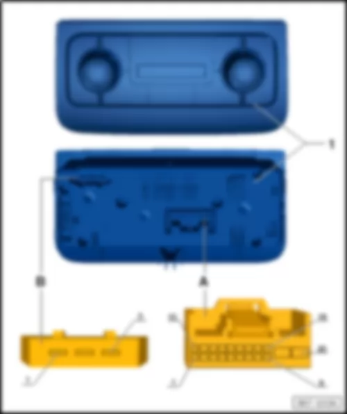
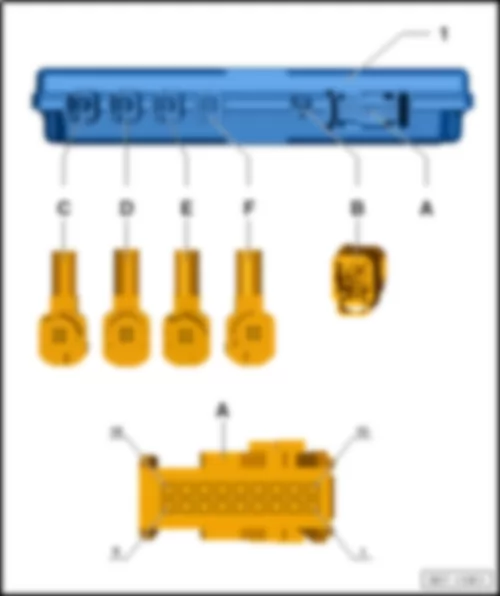
VW TOUAREG 2012 Control unit with display for radio and navigation J503Control unit with display for radio and navigation -J503- |
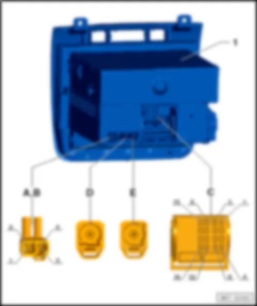
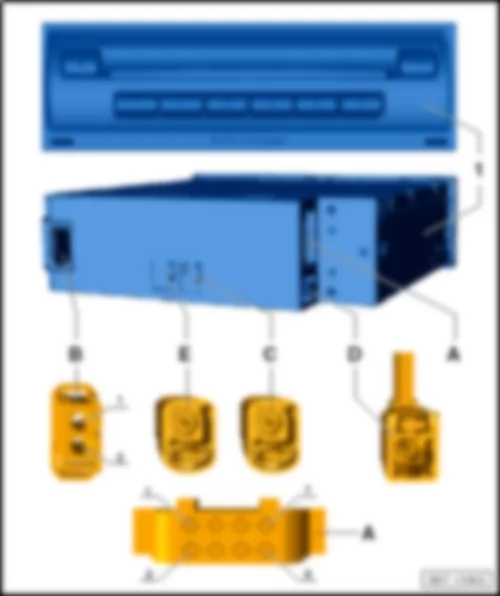
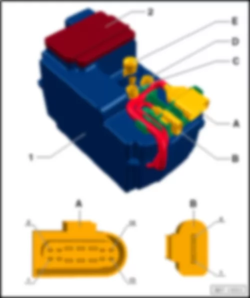
| 1 - | Control unit with display for radio and navigation -J503- | | A,B - | 4-pin connector -T4cp- | Note: | Position C has several connectors. | | q | 8-pin connector -T8j- , brown | | q | 16-pin connector -T16t- , black | | q | 12-pin connector -T12m- , green | | q | 12-pin connector -T12f- , blue | | D - | 2-pin connector -T2fr- | | E - | 2-pin connector -T2ih- |
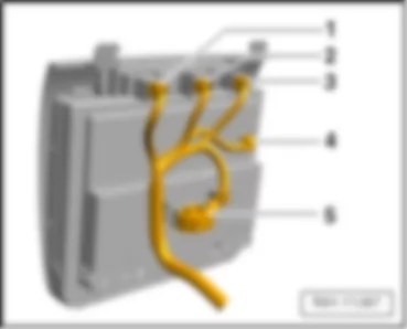
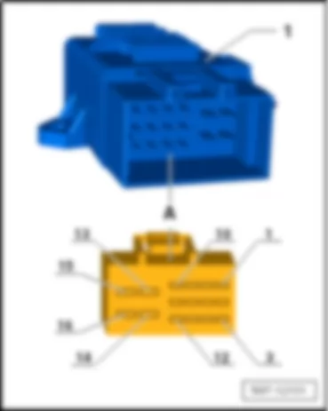
VW TOUAREG 2012 Display unit for front information display and operating unit control unit J685Display unit for front information display and operating unit control unit -J685- |
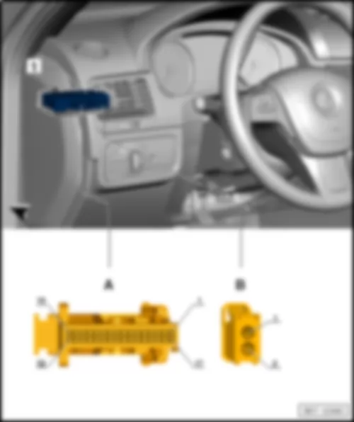
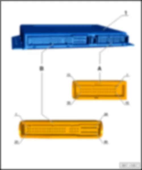
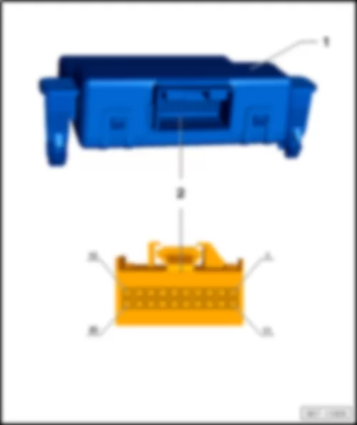
| | | | 1 - | 6-pin connector -T6v- , brown, front passenger airbag deactivated warning lamp -K145- | | 2 - | 6-pin connector -T6q- , blue, hazard warning light switch -E3- | | 3 - | 6-pin connector -T6r- , red, parking aid button -E266- | | 4 - | 5-pin connector -T5s- , grey | | 5 - | 20-pin connector -T20g- , red | | | |
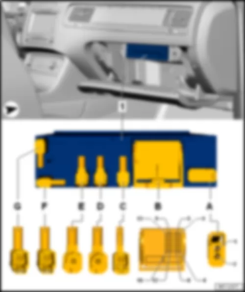
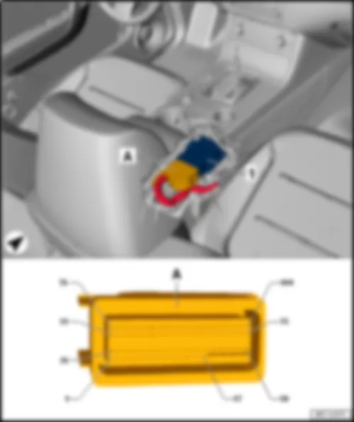
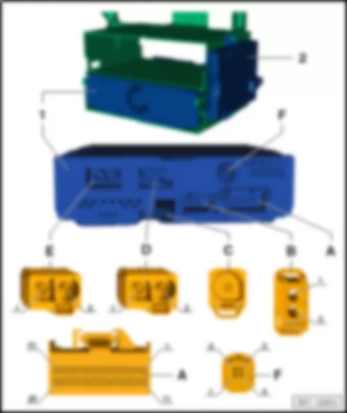
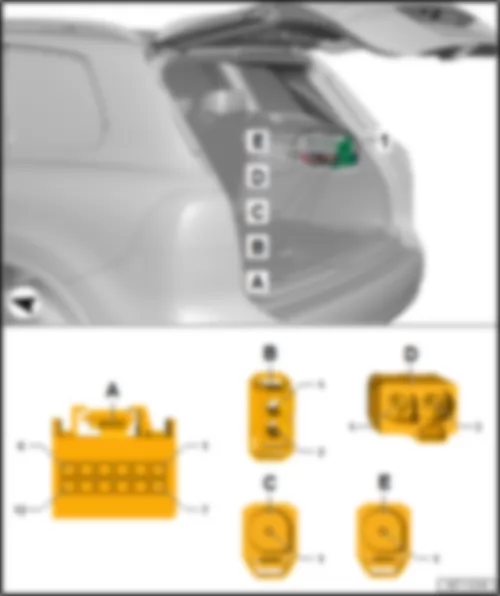
VW TOUAREG 2012 Control unit 1 for information electronics J794Control unit 1 for information electronics -J794- |
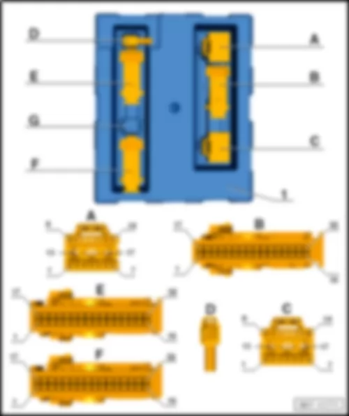
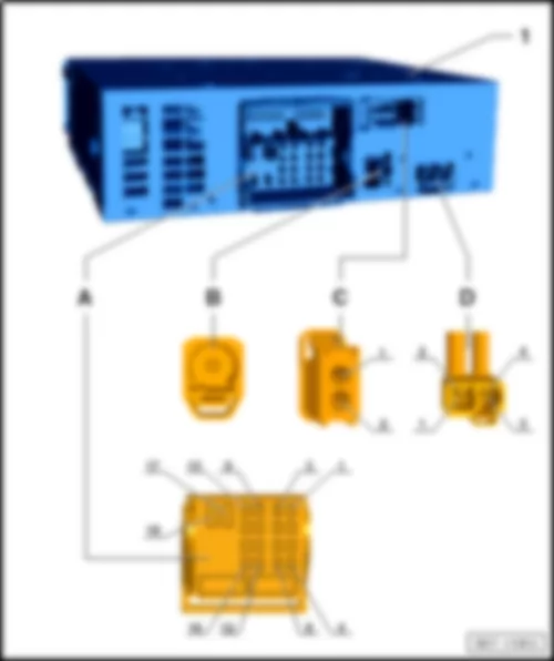
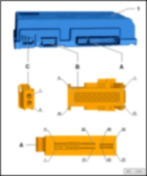
| 1 - | Control unit 1 for information electronics -J794- | | A - | 2-pin connector -T2fd- , black | | q | Fibre optic conductor for Most bus | | q | 8-pin connector -T8w- , black | | q | 8-pin connector -T8x- , brown | | q | 12-pin connector -T12g- , blue | | q | 12-pin connector -T12p- , green | | C - | 2-pin connector -T2fj- , green | | D - | 5-pin connector -T5r- , grey | | q | to display unit for front information display and operating unit control unit -J685- | | E - | 5-pin connector -T5t- , yellow | | q | from connection 2 for external audio sources -R231- | | F - | 2-pin connector -T2- , blue | | G - | 2-pin connector -T2- , violet | | q | from telephone aerial -R65- |
VW TOUAREG 2012 Interface for external multimedia units R215Interface for external multimedia units -R215- |
| 1 - | Interface for external multimedia units -R215- | | A - | 12-pin connector -T12q- |
VW TOUAREG 2012 Voltage stabilizer J532Voltage stabilizer -J532- |
| 1 - | Voltage stabilizer -J532- | | A - | 12-pin connector -T12a- |
VW TOUAREG 2012 Mobile telephone operating electronics control module J412Mobile telephone operating electronics control module -J412- |
| 1 - | Mobile telephone operating electronics control module -J412- | | A - | 54-pin connector -T54b- |
VW TOUAREG 2012 Heated rear seats control unit J786 |
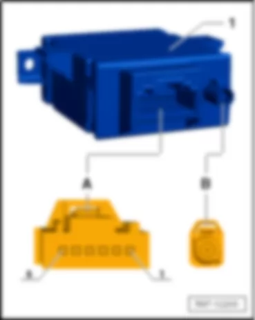
| 1 - | Heated rear seats control unit -J786- | | A - | 16-pin connector -T16o- | | | |
VW TOUAREG 2012 Airbag control unit J234Airbag control unit -J234- |
| 1 - | Airbag control unit -J234- | | A - | 100-pin connector -T100- |
VW TOUAREG 2012 Sliding sunroof adjustment control unit J245Sliding sunroof adjustment control unit -J245- |
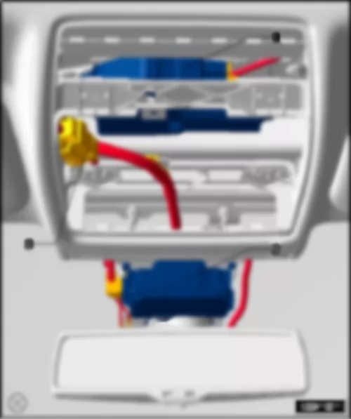
| 1 - | Sliding sunroof adjustment control unit -J245- | | 2 - | Front camera for driver assist systems -R242- | | 3 - | 6-pin connector -T6w- | | 3 - | 10-pin connector -T10q- |
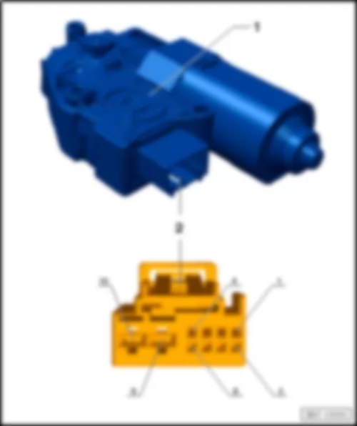
| 1 - | Sliding sunroof adjustment control unit -J245- | | 2 - | 10-pin connector -T10ab- |
VW TOUAREG 2012 Front passenger door control unit J387Front passenger door control unit -J387- |
| 1 - | Front passenger side window regulator motor -V148- | | 1 - | Front passenger door control unit -J387- | | A - | 6-pin connector -T6f- | | B - | 20-pin connector -T20a- | | C - | 16-pin connector -T16d- | | D - | 32-pin connector -T32h- |
VW TOUAREG 2012 Control unit for front passenger multicontour seat J872Control unit for front passenger multicontour seat -J872- |
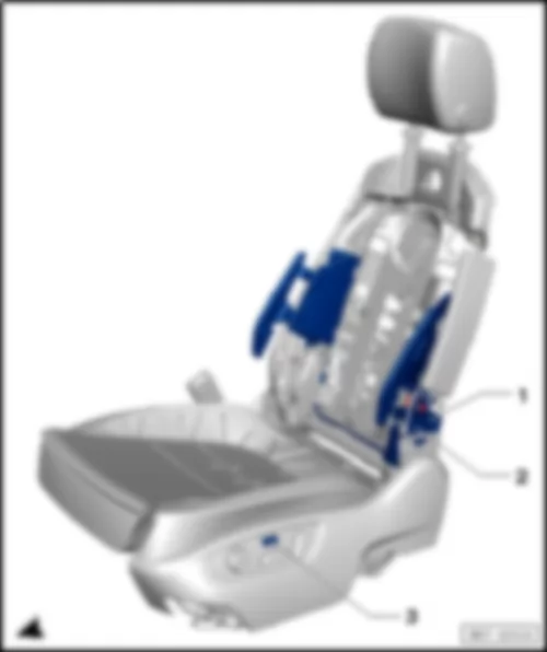
| 1 - | Valve block 1 in front passenger seat -N477- | | 2 - | Compressor for multicontour front passenger seat -V440- | | 3 - | Control unit for front passenger multicontour seat -J872- |
VW TOUAREG 2012 Control unit for front right seat ventilation J799Control unit for front right seat ventilation -J799- |
| 1 - | Control unit for front right seat ventilation -J799- | | A - | 18-pin connector -T18b- | Note: | The installation of the door control unit on the front passenger side is similar to the installation on the driver side. |
VW TOUAREG 2012 Front passenger seat position control unit J720Front passenger seat position control unit -J720- |
| 1 - | Front passenger seat position control unit -J720- | | 2 - | Front passenger seat cushion fan -V391- | Note: | The installation of the door control unit on the front passenger side is similar to the installation on the driver side. |
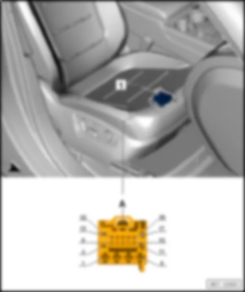
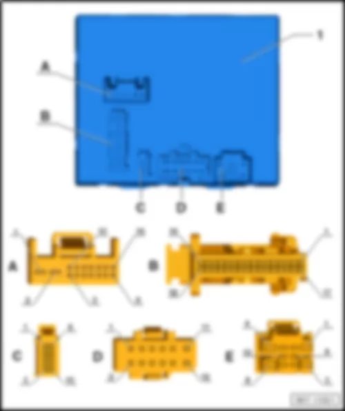
| 1 - | Front passenger seat position control unit -J720- | | A - | 16-pin connector -T16n- | | B - | 32-pin connector -T32l- | | C - | 10-pin connector -T10ah- | | D - | 12-pin connector -T12ab- | | E - | 10-pin connector -T10ai- |
VW TOUAREG 2012 Automatic gearbox control unit J217 |
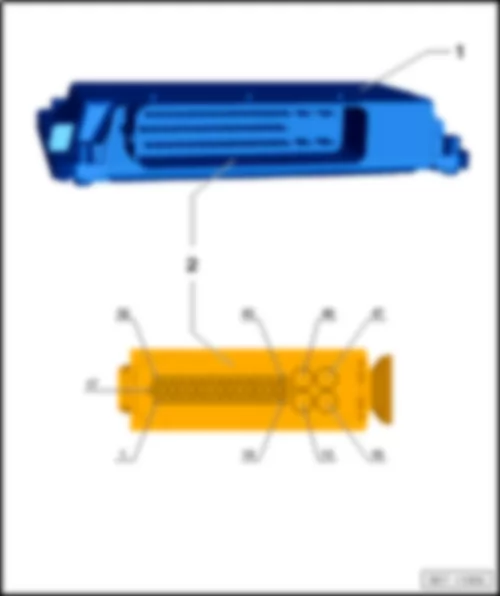
| 1 - | Transfer box control unit -J646- | | 2 - | 47-pin connector -T47a- |
| 1 - | Automatic gearbox control unit -J217- | | A - | 52-pin connector -T52- | | | |
VW TOUAREG 2012 Control unit for front right belt tensioner J855 |
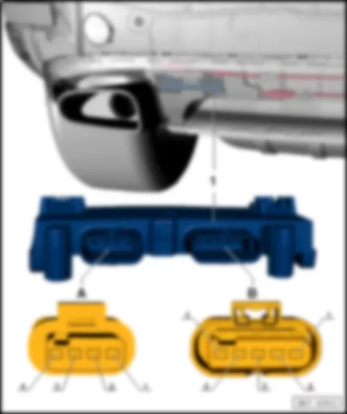
| 1 - | Control unit for front right belt tensioner -J855- | | A - | 5-pin connector -T5ab- | | B - | 4-pin connector -T4ah- |
VW TOUAREG 2012 Control unit for auxiliary hydraulic pump J922 |
| 1 - | Control unit for auxiliary hydraulic pump -J922- | | A - | 8-pin connector -T8e- | | | |
VW TOUAREG 2012 Image processing control unit J851 |
| 1 - | Image processing control unit -J851- | | A - | 12-pin connector -T12j- | | B - | 5-pin connector -T5o- | | | |
VW TOUAREG 2012 Mobile telephone operating electronics control module J412Mobile telephone operating electronics control module -J412- |
| 1 - | Mobile telephone operating electronics control module -J412- | | A - | Telephone aerial connection | | B - | 54-pin connector -T54- | | | |
VW TOUAREG 2012 Rear right door control unit J389Rear right door control unit -J389- |
| 1 - | Rear right window regulator motor -V27- | Note: | The installation of the control unit on the right side is similar to the left side. | | | | | 1 - | Rear right door control unit -J389- | | A - | 6-pin connector -T6h- | | B - | 20-pin connector -T20c- | | C - | 16-pin connector -T16f- | Note: | The illustration may deviate. |
VW TOUAREG 2012 Operating and display unit for rear air conditioning system E265Operating and display unit for rear air conditioning system -E265- |
| 1 - | Operating and display unit for rear air conditioning system -E265- | | A - | 20-pin connector -T20e- | | B - | 3-pin connector -T3r- |
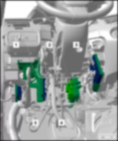
VW TOUAREG 2012 Onboard supply control unit J519Onboard supply control unit -J519- |
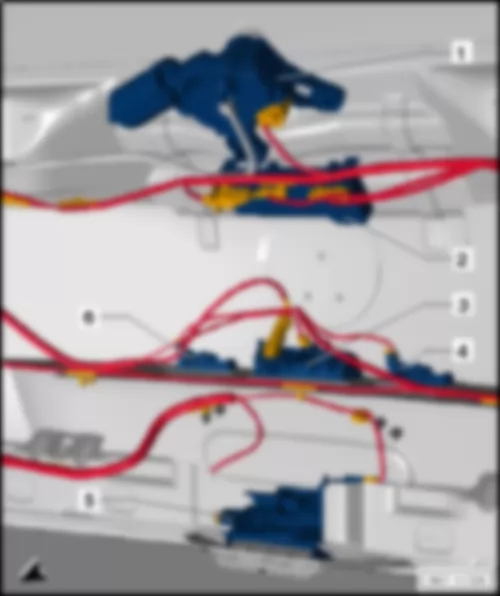
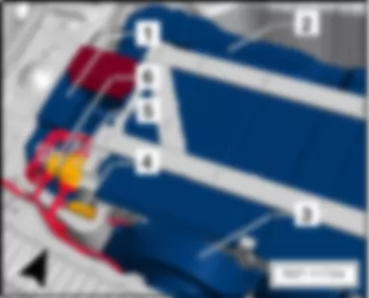
| 1 - | Fuse and relay carrier 1 -SR 1- | | 2 - | Fuse and relay carrier 2 -SR 2- | | 3 - | Onboard supply control unit -J519- | | 4 - | Convenience system central control unit -J393- | | 5 - | Parking aid control unit -J446- |
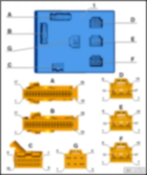
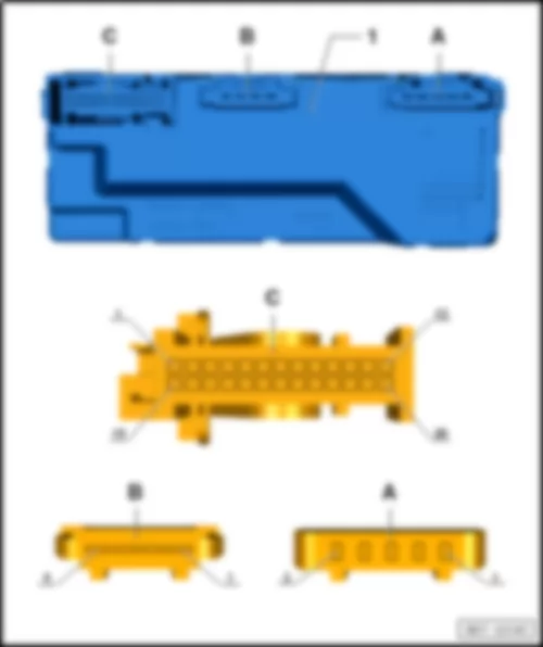
| Connector assignment, onboard supply control unit -J519- | | 1 - | Onboard supply control unit -J519- | | A - | 32-pin connector -T32b- | | B - | 32-pin connector -T32c- | | C - | 16-pin connector -T16a- | | D - | 17-pin connector -T17- | | E - | 17-pin connector -T17a- | | F - | 17-pin connector -T17b- |
| Description of signal for onboard supply control unit -J519- | | Connector | Pin | Terminal | | A | 1 | - | | A | 2 | - | | A | 3 | - | | A | 4 | - | | A | 5 | - | | A | 6 | - | | A | 7 | - | | A | 8 | Hazard warning light button input signal | | A | 9 | Rotary light switch input signal | | A | 10 | - | | A | 11 | - | | A | 12 | - | | A | 13 | - | | A | 14 | - | | A | 15 | - | | A | 16 | - | | A | 17 | Front footwell light, output | | A | 18 | Rotary light switch LIN signal | | A | 19 | - | | A | 20 | - | | A | 21 | - | | A | 22 | - | | A | 23 | - | | A | 24 | Start/stop LED response, output | | A | 25 | - | | A | 26 | Electric steering column lock authorisation signal, output | | A | 27 | - | | A | 28 | Hazard warning button illumination, output | | A | 29 | - | | A | 30 | Start/stop button input signal | | A | 31 | - | | A | 32 | - | | B | 1 | Switch search illumination output (terminal 58st) | | B | 2 | - | | B | 3 | Bonnet ATA contact input signal | | B | 4 | - | | B | 5 | - | | B | 6 | Brake fluid input signal | | B | 7 | - | | B | 8 | - | | B | 9 | Brake pad wear input signal | | B | 10 | Ambient temperature sensor input signal (bumper) | | B | 11 | - | | B | 12 | - | | B | 13 | - | | B | 14 | Front left seat temperature sensor input signal | | B | 15 | - | | B | 16 | Fuse terminal 15 (fuse SB 53) | | B | 17 | Switch search illumination output (terminal 58s) | | B | 18 | - | | B | 19 | Front right seat temperature sensor input signal | | B | 20 | Fuel supply relay output signal | | B | 21 | - | | B | 22 | - | | B | 23 | - | | B | 24 | - | | B | 25 | Universal signal earth (terminal 31-SM) | | B | 26 | - | | B | 27 | Coolant warning input signal | | B | 28 | Washer fluid warning input signal | | B | 29 | Horn activation relay, output | | B | 30 | - | | B | 31 | - | | B | 32 | - | | C | 1 | - | | C | 2 | Wiper motor LIN signal | | C | 3 | - | | C | 4 | LIN signal for air quality sensor, refrigerant pressure sensor, seat heater regulator, garage door opener | | C | 5 | - | | C | 6 | Electric steering column lock LIN signal | | C | 7 | - | | C | 8 | - | | C | 9 | - | | C | 10 | - | | C | 11 | - | | C | 12 | - | | C | 13 | - | | C | 14 | Convenience CAN, low | | C | 15 | Convenience CAN, high | | C | 16 | - | | D | 1 | Servotronic control valve +, output | | D | 2 | - | | D | 3 | Washer pump 2 activation, output | | D | 4 | Washer pump 1 activation, output | | D | 5 | - | | D | 6 | Headlight washer system pump activation, output | | D | 7 | - | | D | 8 | Air conditioner compressor regulating valve +, output | | D | 9 | Interior light dimmer, output | | D | 10 | Air conditioner compressor regulating valve -, output | | D | 11 | - | | D | 12 | Servotronic control valve -, output | | D | 13 | - | | D | 14 | Rear footwell light, output | | D | 15 | Fuse terminal 30 (fuse SB 18) | | D | 16 | Fuse terminal 30 (fuse SB 14) | | D | 17 | Output for interior lights, sun visor, entry lights | | E | 1 | - | | E | 2 | Front left side light, output | | E | 3 | Left main beam flap, output (only xenon) | | E | 4 | Front right side marker output (only NAR) | | E | 5 | Front left turn signal, output | | E | 6 | Front left side marker output (only NAR) | | E | 7 | - | | E | 8 | Left fog light, output | | E | 9 | - | | E | 10 | - | | E | 11 | - | | E | 12 | Left main beam, output | | E | 13 | - | | E | 14 | - | | E | 15 | Left dip beam, output | | E | 16 | Left terminal 30 (fuse SB 22) | | E | 17 | Terminal 31 (earth) | | F | 1 | - | | F | 2 | Right main beam, output | | F | 3 | - | | F | 4 | - | | F | 5 | - | | F | 6 | - | | F | 7 | Front left daytime running light, output | | F | 8 | Right fog light, output | | F | 9 | Right main beam flap, output (only xenon) | | F | 10 | Front right turn signal, output | | F | 11 | - | | F | 12 | Front right side light, output | | F | 13 | - | | F | 14 | Front right daytime running light, output | | F | 15 | Right dip beam, output | | F | 16 | Right terminal 30 (fuse SB 15) | | F | 17 | Terminal 31 (earth) | | G | 1 | Front left seat heater activation, output | | G | 2 | - | | G | 3 | Fuse terminal 30 (fuse SB 20) | | G | 4 | - | | G | 5 | - | | G | 6 | Front right seat heater activation, output |
| Connector assignment, convenience system central control unit -J393- | | 1 - | Convenience system central control unit -J393- | | A - | 17-pin connector -T17c- | | B - | 32-pin connector -T32d- | | C - | 17-pin connector -T17d- | | D - | 2-pin connector -T2h- | | E - | 32-pin connector -T32e- | | F - | 32-pin connector -T32f- |
| Description of signal for convenience system central control unit -J393- | | Connector | Pin | Terminal | | A | 1 | Right reversing light, output | | A | 2 | Power latching system (close), output | | A | 3 | - | | A | 4 | Power latching system (open), output | | A | 5 | Luggage compartment rotary latch motor, output | | A | 6 | Release tank flap, output | | A | 7 | Lock tank flap, output | | A | 8 | - | | A | 9 | - | | A | 10 | Right tail light/brake light, output | | A | 11 | - | | A | 12 | Left turn signal, output | | A | 13 | - | | A | 14 | - | | A | 15 | Terminal 30 (fuse SC33) | | A | 16 | Terminal 30 (fuse SC36) | | A | 17 | Terminal 31 (earth) | | B | 1 | - | | B | 2 | - | | B | 3 | Key withdrawal inhibitor, output signal | | B | 4 | Rear heated window relay activation, output signal | | B | 5 | - | | B | 6 | - | | B | 7 | - | | B | 8 | - | | B | 9 | - | | B | 10 | - | | B | 11 | - | | B | 12 | - | | B | 13 | - | | B | 14 | Registration plate light, output | | B | 15 | Power socket relay activation, output signal | | B | 16 | ATA siren LIN signal | | B | 17 | Electric steering column lock ignition switch, LIN signal | | B | 18 | - | | B | 19 | Convenience CAN, high | | B | 20 | Convenience CAN, low | | B | 21 | - | | B | 22 | - | | B | 23 | - | | B | 24 | - | | B | 25 | - | | B | 26 | - | | B | 27 | - | | B | 28 | - | | B | 29 | - | | B | 30 | - | | B | 31 | - | | B | 32 | LIN signal for air ATA sensor, switches for garage door opener, sliding sunroof, roof roller blind | | C | 1 | - | | C | 2 | - | | C | 3 | - | | C | 4 | - | | C | 5 | Left rear fog light, output | | C | 6 | Left tail light in rear lid, output | | C | 7 | - | | C | 8 | Luggage compartment, output | | C | 9 | - | | C | 10 | - | | C | 11 | Left tail light/brake light, output | | C | 12 | Right tail light in rear lid, output | | C | 13 | Right turn signal, output | | C | 14 | Left reversing light, electronically controlled mirror, output | | C | 15 | Electric steering column lock (motor supply), output | | C | 16 | Terminal 30 (fuse SC31) | | C | 17 | Terminal 31 (earth) | | D | 1 | Central locking aerial, input signal | | D | 2 | Central locking aerial, screening | | E | 1 | - | | E | 2 | Brake light switch input signal (terminal 54) | | E | 3 | Rear lid handle release button input signal | | E | 4 | Rear lid main latch contact, input signal | | E | 5 | Terminal 50 activation relay, output signal | | E | 6 | - | | E | 7 | - | | E | 8 | Rear lid first latch contact, input signal | | E | 9 | - | | E | 10 | - | | E | 11 | Terminal S, input signal | | E | 12 | Terminal 15, input signal | | E | 13 | Terminal 15 (redundant 1), input signal | | E | 14 | - | | E | 15 | Electric steering column lock, enable terminal 15, output signal | | E | 16 | Terminal 15 activation relay, output signal | | E | 17 | - | | E | 18 | High-level brake light, output | | E | 19 | - | | E | 20 | Terminal 15 (redundant 2), input signal | | E | 21 | - | | E | 22 | - | | E | 23 | - | | E | 24 | - | | E | 25 | Position P on automatic gearbox, input signal | | E | 26 | - | | E | 27 | - | | E | 28 | P/N switch or clutch pedal switch input signal | | E | 29 | - | | E | 30 | - | | E | 31 | - | | E | 32 | - | | F | 1 | Start/stop button input signal | | F | 2 | - | | F | 3 | Start/stop button redundant input signal | | F | 4 | - | | F | 5 | Feedback contact input signal for rear lid power latching system closed | | F | 6 | - | | F | 7 | - | | F | 8 | - | | F | 9 | Kessy aerial input signal for rear right door | | F | 10 | Aerial earth for rear right door | | F | 11 | Kessy aerial input signal for rear right door | | F | 12 | Aerial earth for rear left door | | F | 13 | Kessy aerial input signal for luggage compartment | | F | 14 | Aerial earth for luggage compartment | | F | 15 | Kessy aerial input signal, centre console | | F | 16 | Aerial earth, centre console | | F | 17 | - | | F | 18 | - | | F | 19 | - | | F | 20 | - | | F | 21 | - | | F | 22 | - | | F | 23 | - | | F | 24 | - | | F | 25 | - | | F | 26 | - | | F | 27 | - | | F | 28 | - | | F | 29 | Input signal for contact sensor for rear right exterior door handle | | F | 30 | Input signal for contact sensor for front right exterior door handle | | F | 31 | Input signal for contact sensor for rear left exterior door handle | | F | 32 | Input signal for contact sensor for front left exterior door handle |
| Connector assignment of parking aid control unit -J446- | | 1 - | Parking aid control unit -J446- | | A - | 16-pin connector -T16i- | | B - | 12-pin connector -T12c- | | C - | 12-pin connector -T12d- |
VW TOUAREG 2012 Data bus diagnostic interface J533Data bus diagnostic interface -J533- |
| 1 - | Data bus diagnostic interface -J533- | | A - | 32-pin connector -T32a- | | B - | 2-pin connector -T2fm- |
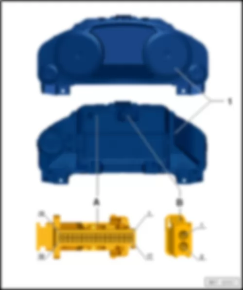
VW TOUAREG 2012 Control unit in dash panel insert J285Control unit in dash panel insert -J285- |
| 1 - | Control unit in dash panel insert -J285- | | A - | 32-pin connector -T32- | | B - | 2-pin connector -T2fn- |
| Description of signal for control unit in dash panel insert -J285- | | Connector | Pin | Terminal | | A | 1 | Ring circuit break diagnostic, Most bus | | A | 2 | - | | A | 3 | CAN bus, low | | A | 4 | CAN bus, high | | A | 5 | Tank sensor earth | | A | 6 | Tank sender 1 signal input | | A | 7 | Tank sender 1 signal input | | A | 8 | - | | A | 9 | Tank sender 2 signal input | | A | 10 | Tank sender 2 signal input | | A | 11 | - | | A | 12 | - | | A | 13 | - | | A | 14 | - | | A | 15 | - | | A | 16 | - | | A | 17 | - | | A | 18 | - | | A | 19 | - | | A | 20 | - | | A | 21 | - | | A | 22 | - | | A | 23 | - | | A | 24 | - | | A | 25 | - | | A | 26 | - | | A | 27 | - | | A | 28 | - | | A | 29 | Terminal 31 earth | | A | 30 | Terminal 31 earth | | A | 31 | Terminal 30 (SC52) | | A | 32 | Terminal 30 (SC52) |
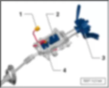
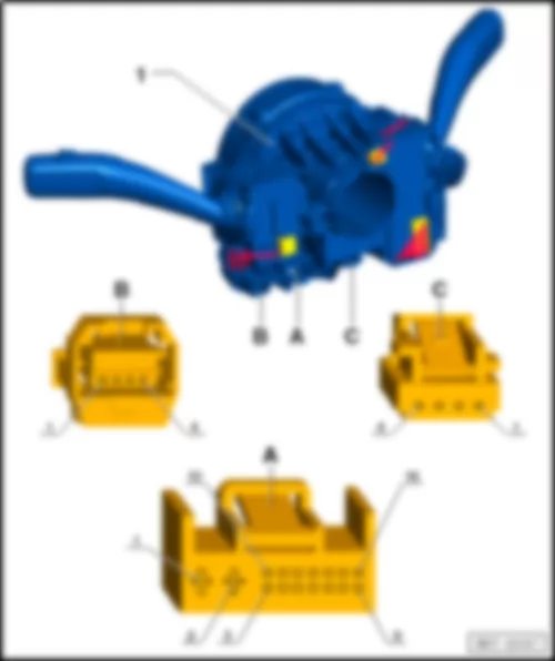
VW TOUAREG 2012 Steering column electronics control unit J527Steering column electronics control unit -J527- |
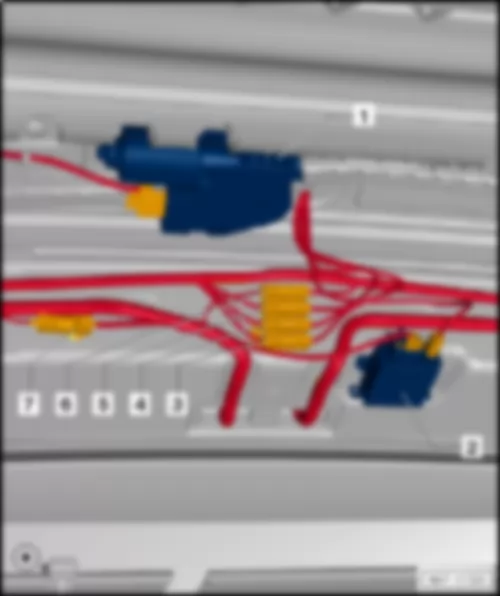
| 1 - | 6-pin connector -T6an- | | 2 - | Control unit for electronic steering column lock -J764- | | 3 - | Steering column electronics control unit -J527- | | 4 - | Control unit for electrically adjustable steering column -J866- | | | | | 1 - | Steering column electronics control unit -J527- | | A - | 16-pin connector -T16b- , black | | B - | 4-pin connector -T4b- , yellow | | C - | 4-pin connector -T4ci- , black |
VW TOUAREG 2012 Control unit for electronic steering column lock J764Control unit for electronic steering column lock -J764- |
| 1 - | Control unit for electronic steering column lock -J764- | | A - | 6-pin connector -T6s- | | | |
VW TOUAREG 2012 Control unit for electrically adjustable steering column J866Control unit for electrically adjustable steering column -J866- |
| 1 - | Control unit for electrically adjustable steering column -J866- | | 2 - | 18-pin connector -T18c- | | | |
VW TOUAREG 2012 Driver door control unit J386Driver door control unit -J386- |
| 1 - | Driver side window regulator motor -V147- | | 1 - | Driver door control unit -J386- | | A - | 6-pin connector -T6e- | | B - | 20-pin connector -T20- | | C - | 16-pin connector -T16c- | | D - | 32-pin connector -T32g- |
VW TOUAREG 2012 Control unit for driver multicontour seat J873Control unit for driver multicontour seat -J873- |
| 1 - | Valve block 1 in driver seat -N475- | | 2 - | Compressor for multicontour driver seat -V439- | | 3 - | Control unit for driver multicontour seat -J873- |
VW TOUAREG 2012 Control unit for front left seat ventilation J800Control unit for front left seat ventilation -J800- |
| 1 - | Control unit for front left seat ventilation -J800- | | A - | 18-pin connector -T18a- |
VW TOUAREG 2012 Control unit for front left belt tensioner J854 |
| 1 - | Control unit for front left belt tensioner -J854- | | A - | 5-pin connector -T5aa- | | B - | 4-pin connector -T4ag- |
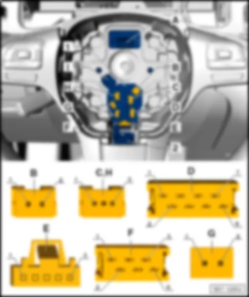
VW TOUAREG 2012 Multifunction steering wheel control unit J453Multifunction steering wheel control unit -J453- |
| 1 - | Multifunction steering wheel control unit -J453- | | A - | 12-pin connector -T12h- | | B - | 2-pin connector -T2hy- | | C - | 3-pin connector -T3ak- | | D - | 8-pin connector -T8s- | | E - | 5-pin connector -T5v- | | F - | 6-pin connector -T6aj- | | G - | 2-pin connector -T2hz- | | H - | 3-pin connector -T3al- | | I - | 2-pin connector -T2cz- |
VW TOUAREG 2012 Driver seat adjustment control unit J810Driver seat adjustment control unit -J810- |
| 1 - | Driver seat adjustment control unit -J810- | | 2 - | Driver seat cushion fan -V390- |
| 1 - | Driver seat adjustment control unit -J810- | | A - | 16-pin connector -T16m- | | B - | 32-pin connector -T32k- | | C - | 10-pin connector -T10bg- | | D - | 12-pin connector -T12aa- | | E - | 10-pin connector -T10af- |
VW TOUAREG 2012 Tyre Pressure Monitoring System control unit J502 |
| 1 - | Tyre Pressure Monitoring System control unit -J502- | | A - | 12-pin connector -T12n- | | | |
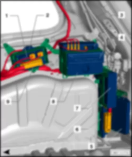
VW TOUAREG 2012 Fuse assignment in fuse holder DFuse assignment in fuse holder D |
| 1 - | Battery monitor control unit -J367- | | 2 - | Connection and distribution box 3 -SX3- | | 3 - | Seat coupling station | | 4 - | Seat coupling station | | 5 - | Seat coupling station | | | |
VW TOUAREG 2012 Rear left door control unit J388 |
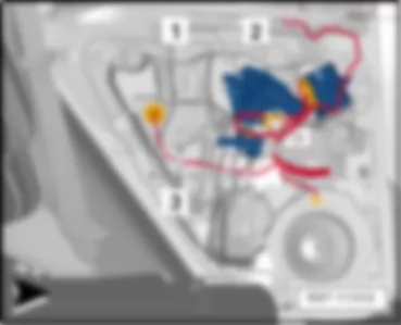
| 2 - | Rear left door control unit -J388- | | 3 - | Rear left aerial for entry and start authorisation -R165- | | 1 - | Rear left door control unit -J388- | | A - | 6-pin connector -T6g- | | B - | 20-pin connector -T20b- | | C - | 16-pin connector -T16e- | Note: | The illustration may deviate. |
VW TOUAREG 2012 Control unit for vehicle location system J895 |
| 1 - | Control unit for vehicle location system -J895- | | A - | 16-pin connector -T16s- | | B - | GPS aerial connection, blue | | C - | GSM aerial connection, violet |
| | | | | | | | | | | |

