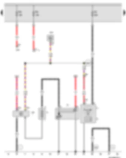
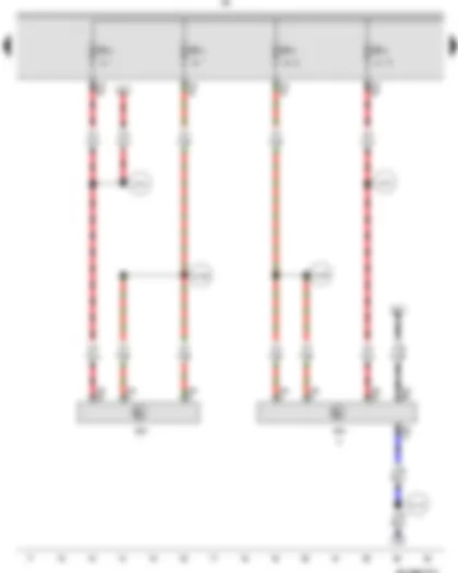
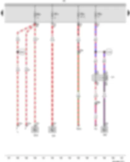
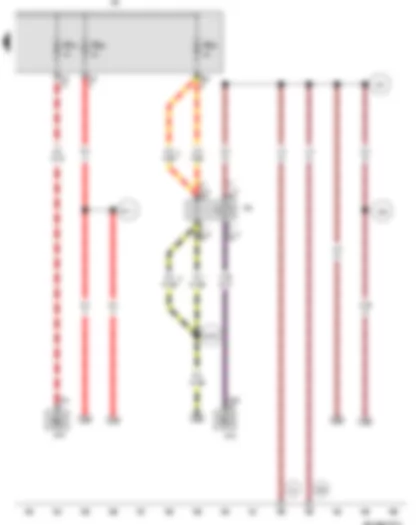
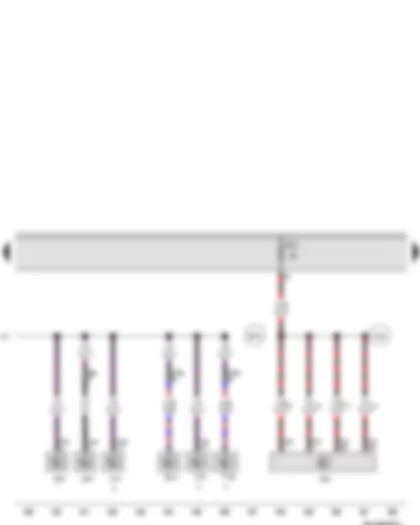
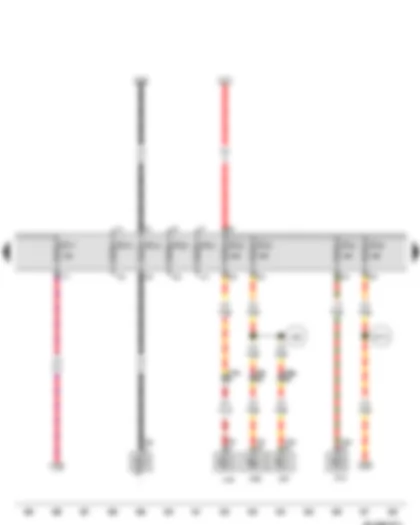
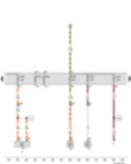
Wiring Diagram VW GOLF A6 2011 - Battery - Starter - Alternator - Onboard supply control unit - Fuse 1 in fuse holder A

| A | Battery |
| B | Starter |
| C | Alternator |
| C1 | Voltage regulator |
| J519 | Onboard supply control unit |
| SA1 | Fuse 1 in fuse holder A |
| T2 | 2-pin connector |
| T4t | 4-pin connector |
| T52c | 52-pin connector |
| 1 | Earth strap, battery - body |
| 14 | Earth point, on gearbox |
| 508 | Threaded connection (30) on E-box |
| 652 | Earth point, engine and gearbox earth |
| B177 | Connection (61), in interior wiring harness |
| * | Only models with 90A/ 110A alternator |
| *2 | Only models with 140 A alternator |
| *3 | Wiring colour depends on equipment |
| *4 | Up to February 2012 |
| *5 | Only models with dual clutch gearbox 0AM |
| *6 | Only models with 1.6l engine |
| *7 | Only models with 1.4l engine |
| *8 | Only models with 2.0l engine |
| *9 | From February 2012 |
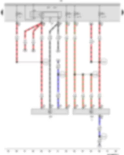
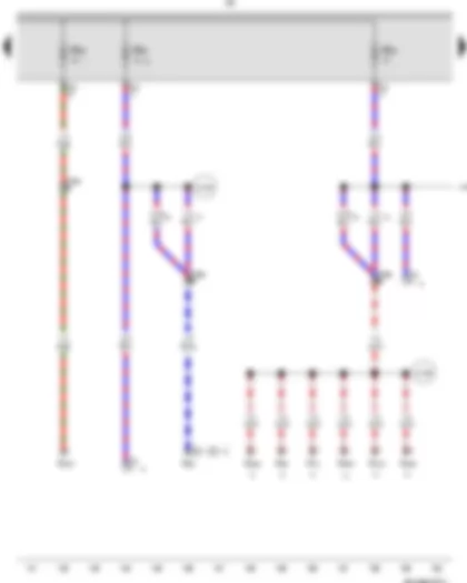
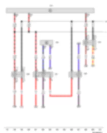
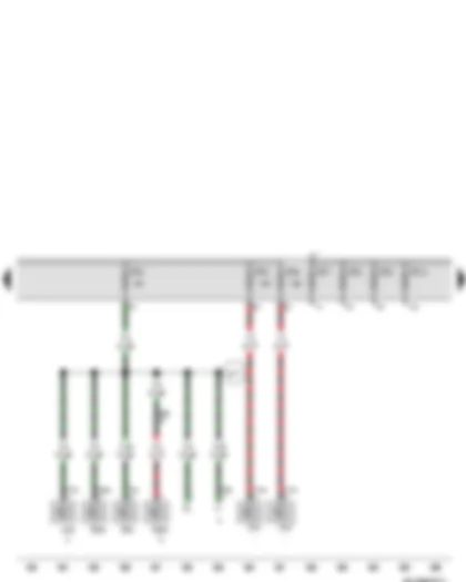
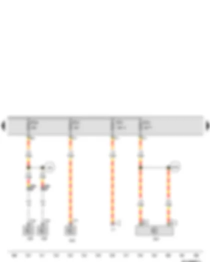
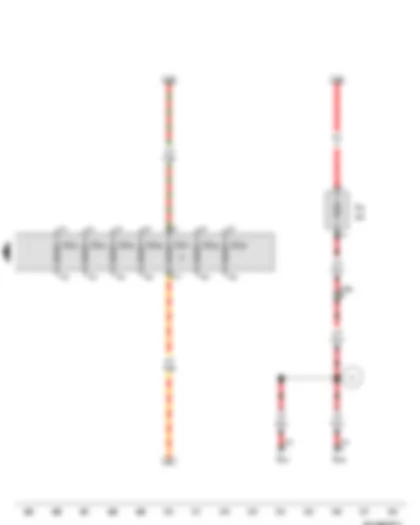
Wiring Diagram VW GOLF A6 2011 - Battery - Starter - Alternator - Battery monitor control unit - Data bus diagnostic interface - Fuse 1 in fuse holder A - Fuse 2 in fuse holder A - Fuse 3 in fuse holder A
| A | Battery |
| B | Starter |
| C | Alternator |
| C1 | Voltage regulator |
| J367 | Battery monitor control unit |
| J500 | Power steering control unit |
| J533 | Data bus diagnostic interface, in left footwell, near centre console |
| SA1 | Fuse 1 in fuse holder A |
| SA2 | Fuse 2 in fuse holder A |
| SA3 | Fuse 3 in fuse holder A |
| T2a | 2-pin connector |
| T2bn | 2-pin connector |
| T2c | 2-pin connector |
| T4x | 4-pin connector |
| T20 | 20-pin connector |
| 1 | Earth strap, battery - body |
| 14 | Earth point, on gearbox |
| 652 | Earth point, engine and gearbox earth |
| B698 | Connection 3 (LIN bus) in main wiring harness |
| * | Only models with start/stop system |
| *2 | Radiator fan connection |
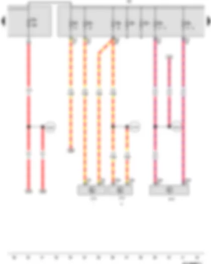
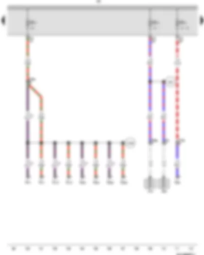
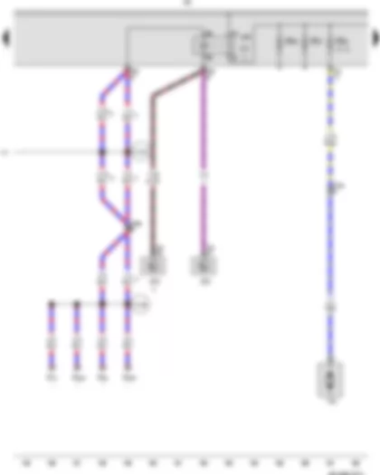
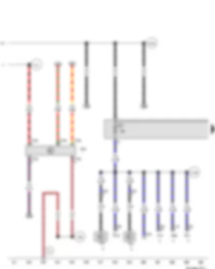
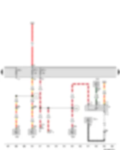
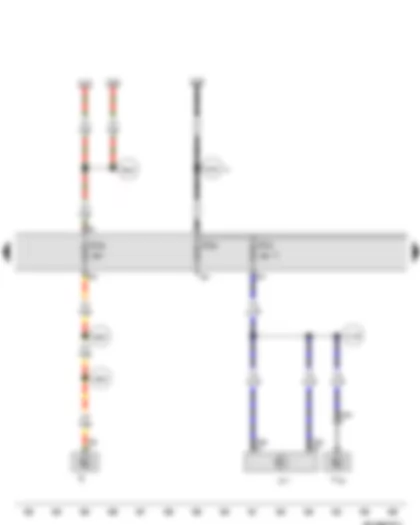
Wiring Diagram VW GOLF A6 2011 - Onboard supply control unit - Mechatronic unit for dual clutch gearbox - Fuse 5 in fuse holder A - Fuse holder B
| J519 | Onboard supply control unit |
| J743 | Mechatronic unit for dual clutch gearbox |
| SB1 | Fuse 1 on fuse holder B |
| SB2 | Fuse 2 on fuse holder B |
| SB3 | Fuse 3 on fuse holder B |
| SA5 | Fuse 5 in fuse holder A |
| SB | Fuse holder B |
| SB5 | Fuse 5 on fuse holder B |
| SB7 | Fuse 7 on fuse holder B |
| SB11 | Fuse 11 on fuse holder B |
| T20e | 20-pin connector |
| T25 | 25-pin connector |
| T40 | 40-pin connector |
| T52a | 52-pin connector |
| B169 | Positive connection 1 (30), in interior wiring harness |
| B319 | Positive connection 5 (30a) in main wiring harness |
| D104 | Positive connection 2 (30a), in engine compartment wiring harness |
| * | Only models with dual clutch gearbox 0AM |
| *2 | Only models with dual clutch gearbox 02E |
| *3 | Up to August 2010 |
| *4 | From August 2010 |
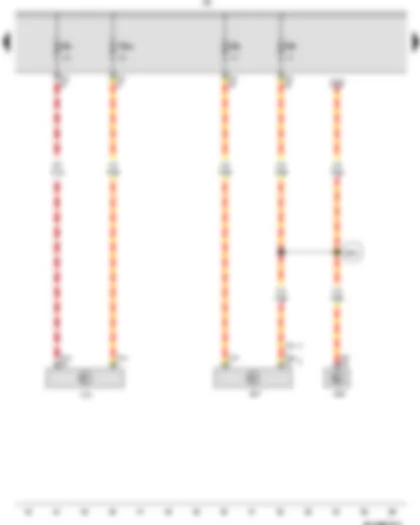
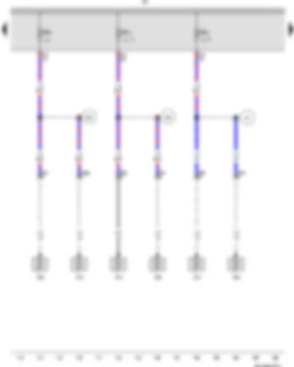
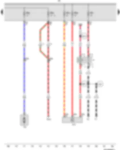
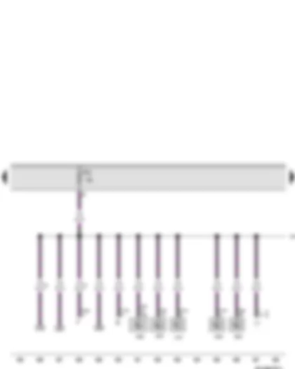
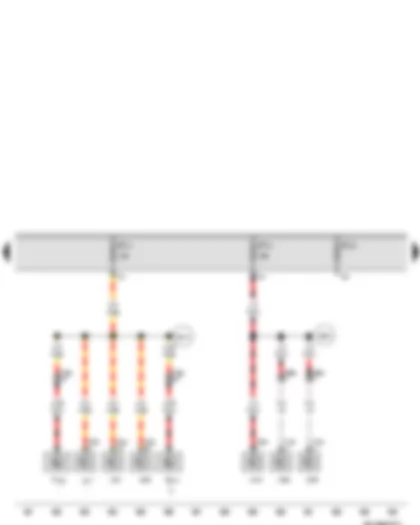
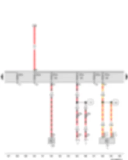
Wiring Diagram VW GOLF A6 2011 - ABS control unit - Control unit in dash panel insert - Steering column electronics control unit - Fuse holder B
| J104 | ABS control unit |
| J285 | Control unit in dash panel insert |
| J527 | Steering column electronics control unit |
| SB | Fuse holder B |
| SB4 | Fuse 4 on fuse holder B |
| SB6 | Fuse 6 on fuse holder B |
| SB25 | Fuse 25 on fuse holder B |
| T16f | 16-pin connector |
| T32 | 32-pin connector |
| T40 | 40-pin connector |
| T47c | 47-pin connector |
| B504 | Positive connection 8 (30a), in interior wiring harness |
| * | Only models with start/stop system |
| *2 | Up to July 2010 |
| *3 | From August 2010 |
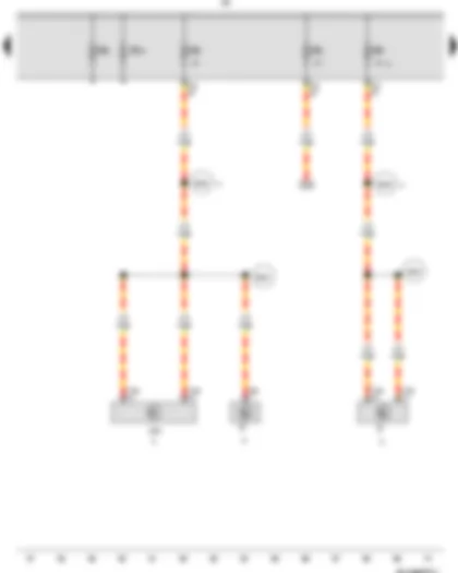
Wiring Diagram VW GOLF A6 2011 - Control unit with display for radio and navigation - Radio - Fuse holder B
| J503 | Control unit with display for radio and navigation |
| R | Radio |
| SB | Fuse holder B |
| SB8 | Fuse 8 on fuse holder B |
| SB9 | Fuse 9 on fuse holder B |
| SB18 | Fuse 18 on fuse holder B |
| T8a | 8-pin connector |
| T16b | 16-pin connector |
| T40 | 40-pin connector |
| B224 | Connection 1 (radio), in interior wiring harness |
| B225 | Connection 2 (radio), in interior wiring harness |
| * | Only models with start/stop system |
| *2 | Only models with radio RCD 310/RCD 510 |
| *3 | Only models with radio navigation system |
| *4 | From February 2012 |
| *5 | Only models with radio |
Wiring Diagram VW GOLF A6 2011 - Engine control unit - Fuse holder B
| J623 | Engine control unit |
| SB | Fuse holder B |
| SB10 | Fuse 10 on fuse holder B |
| SB13 | Fuse 13 on fuse holder B |
| T40 | 40-pin connector |
| T94 | 94-pin connector |
| D78 | Positive connection 1 (30a), in engine compartment wiring harness |
| D110 | Connection 8 in engine compartment wiring harness |
| D182 | Connection 3 (87a) in engine compartment wiring harness |
| * | Only models with start/stop system |
| *2 | Only models with 1.4l engine |
Wiring Diagram VW GOLF A6 2011 - Motronic control unit - Main relay - Engine control unit - Fuse holder B
| J220 | Motronic control unit |
| J271 | Main relay |
| J317 | Terminal 30 voltage supply relay |
| J623 | Engine control unit |
| SB | Fuse holder B |
| SB10 | Fuse 10 on fuse holder B |
| SB13 | Fuse 13 on fuse holder B |
| T40 | 40-pin connector |
| T80 | 80-pin connector |
| T94 | 94-pin connector |
| D78 | Positive connection 1 (30a), in engine compartment wiring harness |
| D110 | Connection 8 in engine compartment wiring harness |
| D182 | Connection 3 (87a) in engine compartment wiring harness |
| * | Only models with 1.6l engine |
| *2 | Only models with 2.0l engine |
| *3 | Only models with 1.4l engine |
Wiring Diagram VW GOLF A6 2011 - Fuse holder B - Fuse 14 on fuse holder B - Fuse 15 on fuse holder B - Lambda probe heater - Lambda probe 1 heater after catalytic converter
| N70 | Ignition coil 1 with output stage |
| N80 | Activated charcoal filter solenoid valve 1 |
| N127 | Ignition coil 2 with output stage |
| N291 | Ignition coil 3 with output stage |
| N292 | Ignition coil 4 with output stage |
| SB | Fuse holder B |
| SB14 | Fuse 14 on fuse holder B |
| SB15 | Fuse 15 on fuse holder B |
| T4bg | 4-pin connector |
| T4v | 4-pin connector |
| T14a | 14-pin connector |
| T40 | 40-pin connector |
| Z19 | Lambda probe heater |
| Z29 | Lambda probe 1 heater after catalytic converter |
| D206 | Connection 4 (87a) in engine prewiring harness |
| E30 | Connection (87a), in engine wiring harness |
| * | Only models with 1.4l engine |
| *2 | Only models with 1.6l engine |
Wiring Diagram VW GOLF A6 2011 - Fuse holder B - Fuse 15 on fuse holder B - Fuse 21 on fuse holder B - Lambda probe heater - Lambda probe heater 2 - Lambda probe 1 heater after catalytic converter
| SB | Fuse holder B |
| SB15 | Fuse 15 on fuse holder B |
| SB21 | Fuse 21 on fuse holder B |
| T4bg | 4-pin connector |
| T4bl | 4-pin connector |
| T4v | 4-pin connector |
| T6w | 6-pin connector |
| T40 | 40-pin connector |
| Z19 | Lambda probe heater |
| Z28 | Lambda probe heater 2 |
| Z29 | Lambda probe 1 heater after catalytic converter |
| E7 | Connection (87a), in Motronic wiring harness |
| E30 | Connection (87a), in engine wiring harness |
| * | Only models with 1.6l engine |
| *2 | Only models with 2.0l engine |
| *3 | Only models with start/stop system |
Wiring Diagram VW GOLF A6 2011 - Clutch position sender - Continued coolant circulation relay - Data bus diagnostic interface - Engine control unit - Fuse holder B - Fuse 12 on fuse holder B - Fuse 22 on fuse holder B - Fuse 23 on fuse holder B
| F | Brake light switch |
| G476 | Clutch position sender |
| J151 | Continued coolant circulation relay |
| J533 | Data bus diagnostic interface, in left footwell, near centre console |
| J623 | Engine control unit |
| N276 | Fuel pressure regulating valve |
| SB | Fuse holder B |
| SB12 | Fuse 12 on fuse holder B |
| SB22 | Fuse 22 on fuse holder B |
| SB23 | Fuse 23 on fuse holder B |
| T2yg | 2-pin connector |
| T4bc | 4-pin connector |
| T5m | 5-pin connector |
| T14a | 14-pin connector |
| T20 | 20-pin connector |
| T40 | 40-pin connector |
| T94 | 94-pin connector |
| V51 | Continued coolant circulation pump |
| B350 | Positive connection 1 (87a) in main wiring harness |
| D183 | Connection 4 (87a) in engine compartment wiring harness |
| * | Only models with 2.0l engine |
| *2 | Only models with start/stop system |
| *3 | Only models with manual gearbox |
| *4 | Up to February 2012 |
| *5 | From February 2012 |
Wiring Diagram VW GOLF A6 2011 - Activated charcoal filter solenoid valve 1 - Fuel pressure regulating valve - Fuse holder B - Fuse 23 on fuse holder B - Fuse 24 on fuse holder B
| N75 | Charge pressure control solenoid valve |
| N80 | Activated charcoal filter solenoid valve 1 |
| N205 | Camshaft control valve 1 |
| N249 | Turbocharger air recirculation valve |
| N276 | Fuel pressure regulating valve |
| N316 | Intake manifold flap valve |
| N428 | Valve for oil pressure control |
| SB | Fuse holder B |
| SB23 | Fuse 23 on fuse holder B |
| SB24 | Fuse 24 on fuse holder B |
| T4x | 4-pin connector |
| T14a | 14-pin connector |
| T40 | 40-pin connector |
| D180 | Connection (87a), in engine compartment wiring harness |
| D189 | Connection (87a) in engine prewiring harness |
| * | Only models with 1.4l engine |
| *2 | Only models with 1.6l engine |
| *3 | Only models with 2.0l engine |
| *4 | Radiator fan connection |
| *5 | Up to February 2012 |
| *6 | From February 2012 |
Wiring Diagram VW GOLF A6 2011 - Additional coolant pump relay - Engine control unit - Fuse holder B - Coolant circulation pump
| J496 | Additional coolant pump relay |
| J623 | Engine control unit |
| J757 | Engine component current supply relay |
| N75 | Charge pressure control solenoid valve |
| N80 | Activated charcoal filter solenoid valve 1 |
| N205 | Camshaft control valve 1 |
| N249 | Turbocharger air recirculation valve |
| SB | Fuse holder B |
| SB20 | Fuse 20 on fuse holder B |
| SB27 | Fuse 27 on fuse holder B |
| SB28 | Fuse 28 on fuse holder B |
| T14a | 14-pin connector |
| T40 | 40-pin connector |
| T94 | 94-pin connector |
| V50 | Coolant circulation pump |
| D180 | Connection (87a), in engine compartment wiring harness |
| D196 | Connection 2 (87a) in engine prewiring harness |
| * | Only models with 1.4l engine |
| *2 | Only models with start/stop system |
| *3 | Only models with 2.0l engine |
| *4 | Up to February 2012 |
| *5 | From February 2012 |
Wiring Diagram VW GOLF A6 2011 - Dual tone horn relay - Onboard supply control unit - Fuse holder B - Coolant circulation pump
| H2 | Treble horn |
| H7 | Bass horn |
| J4 | Dual tone horn relay |
| J519 | Onboard supply control unit |
| N276 | Fuel pressure regulating valve |
| SB | Fuse holder B |
| SB16 | Fuse 16 on fuse holder B |
| SB17 | Fuse 17 on fuse holder B |
| SB20 | Fuse 20 on fuse holder B |
| SB26 | Fuse 26 on fuse holder B |
| T14a | 14-pin connector |
| T40 | 40-pin connector |
| T52a | 52-pin connector |
| T52b | 52-pin connector |
| T52c | 52-pin connector |
| V50 | Coolant circulation pump |
| A90 | Connection (dual tone horn), in dash panel wiring harness |
| B318 | Positive connection 4 (30a) in main wiring harness |
| B521 | Connection (dual tone horn), in main wiring harness |
| * | Only models with 1.4l engine |
| *2 | Only models with 2.0l engine |
| *3 | Up to January 2010 |
| *4 | From January 2010 |
| *5 | Up to February 2012 |
| *6 | From February 2012 |
Wiring Diagram VW GOLF A6 2011 - X-contact relief relay - Wiper motor control unit - Onboard supply control unit - Fuse holder B
| J59 | X-contact relief relay |
| J400 | Wiper motor control unit, in left footwell, near centre console |
| J519 | Onboard supply control unit |
| SB | Fuse holder B |
| SB19 | Fuse 19 on fuse holder B |
| SB29 | Fuse 29 on fuse holder B |
| SB30 | Fuse 30 on fuse holder B |
| T4q | 4-pin connector |
| T40 | 40-pin connector |
| T52b | 52-pin connector |
| 44 | Earth point, lower part of left A-pillar |
| 367 | Earth connection 2, in main wiring harness |
| 389 | Earth connection 24, in main wiring harness |
| 605 | Earth point, on top end of steering column |
| B111 | Positive connection 1 (30a), in interior wiring harness |
| B162 | Connection (75a), in interior wiring harness |
| * | Up to January 2010 |
| *2 | From January 2010 |
Wiring Diagram VW GOLF A6 2011 - Terminal 15 voltage supply relay - Onboard supply control unit - Engine control unit - Terminal 50 voltage supply relay - Starter relay 1 - Starter relay 2
| J329 | Terminal 15 voltage supply relay |
| J519 | Onboard supply control unit |
| J623 | Engine control unit |
| J682 | Terminal 50 voltage supply relay |
| J906 | Starter relay 1 |
| J907 | Starter relay 2 |
| T52b | 52-pin connector |
| T52c | 52-pin connector |
| T94 | 94-pin connector |
| A41 | Positive connection (50), in dash panel wiring harness |
| B163 | Positive connection 1 (15), in interior wiring harness |
| * | Only models with start/stop system |
| *2 | Up to January 2010 |
| *3 | From January 2010 |
Wiring Diagram VW GOLF A6 2011 - Fuse 1 on fuse holder C - Left headlight range control motor
| E102 | Headlight range control regulator |
| G70 | Air mass meter |
| J532 | Voltage stabiliser |
| J745 | Control unit for cornering light and headlight range control |
| J869 | Control unit for structure-borne sound |
| SC1 | Fuse 1 on fuse holder C |
| T5d | 5-pin connector |
| T8e | 8-pin connector |
| T10i | 10-pin connector |
| T12ac | 12-pin connector |
| T12v | 12-pin connector |
| T16d | 16-pin connector |
| T26 | 26-pin connector |
| V48 | Left headlight range control motor |
| V49 | Right headlight range control motor |
| 47 | Earth point, in front right footwell |
| 366 | Earth connection 1, in main wiring harness |
| A41 | Positive connection (50), in dash panel wiring harness |
| A192 | Positive connection 3 (15a) in dash panel wiring harness |
| B163 | Positive connection 1 (15), in interior wiring harness |
| * | Only models with start/stop system |
| *2 | Only models with automatic headlight range control |
| *3 | Only models with xenon headlights |
| *4 | Only models with 2.0l engine |
Wiring Diagram VW GOLF A6 2011 - Control unit in dash panel insert - Data bus diagnostic interface - Fuel pump control unit - Engine control unit - Fuse 2 on fuse holder C
| E1 | Light switch |
| F | Brake light switch |
| J17 | Fuel pump relay |
| J104 | ABS control unit |
| J285 | Control unit in dash panel insert |
| J533 | Data bus diagnostic interface, in left footwell, near centre console |
| J538 | Fuel pump control unit |
| J623 | Engine control unit |
| SC2 | Fuse 2 on fuse holder C |
| T4bc | 4-pin connector |
| T10h | 10-pin connector |
| T10n | 10-pin connector |
| T20 | 20-pin connector |
| T32 | 32-pin connector |
| T47c | 47-pin connector |
| T94 | 94-pin connector |
| B278 | Positive connection 2 (15a) in main wiring harness |
| * | Only models with 1.6l engine |
| *2 | Only models with start/stop system |
| *3 | Up to February 2012 |
| *4 | Up to January 2010 |
| *5 | From January 2010 |
Wiring Diagram VW GOLF A6 2011 - Selector lever - Tiptronic switch - Motronic control unit - Airbag control unit - Power steering control unit - Mechatronic unit for dual clutch gearbox - Fuse 3 on fuse holder C
| E313 | Selector lever |
| F189 | Tiptronic switch |
| J220 | Motronic control unit |
| J234 | Airbag control unit, in left footwell, near centre console |
| J500 | Power steering control unit |
| J743 | Mechatronic unit for dual clutch gearbox |
| SC3 | Fuse 3 on fuse holder C |
| T3dt | 3-pin connector |
| T6z | 6-pin connector |
| T10s | 10-pin connector |
| T20e | 20-pin connector |
| T25 | 25-pin connector |
| T50 | 50-pin connector |
| T80 | 80-pin connector |
| A200 | Positive connection 5 (15a) in dash panel wiring harness |
| B278 | Positive connection 2 (15a) in main wiring harness |
| * | Only models with 1.6l engine |
| *2 | Only models with dual clutch gearbox 02E |
| *3 | Only models with dual clutch gearbox 0AM |
| *4 | Only models with 6-speed automatic gearbox and Tiptronic |
| *5 | Up to February 2012 |
| *6 | From February 2012 |
Wiring Diagram VW GOLF A6 2011 - Left gas discharge bulb control unit - Fuse 4 on fuse holder C - Fuse 5 on fuse holder C - Fuse 6 on fuse holder C - Fuse 7 on fuse holder C - Fuse 8 on fuse holder C - Fuse 9 on fuse holder C - Fuse 10 on fuse holder C
| E256 | TCS and ESP button |
| F4 | Reversing light switch |
| G65 | High-pressure sender |
| G266 | Oil level and oil temperature sender |
| J343 | Left gas discharge bulb control unit |
| J344 | Right gas discharge bulb control unit |
| J446 | Parking aid control unit |
| SC4 | Fuse 4 on fuse holder C |
| SC5 | Fuse 5 on fuse holder C |
| SC6 | Fuse 6 on fuse holder C |
| SC7 | Fuse 7 on fuse holder C |
| SC8 | Fuse 8 on fuse holder C |
| SC9 | Fuse 9 on fuse holder C |
| SC10 | Fuse 10 on fuse holder C |
| T3c | 3-pin connector |
| T6a | 6-pin connector |
| T6ad | 6-pin connector |
| T6z | 6-pin connector |
| T14d | 14-pin connector |
| T14e | 14-pin connector |
| T16j | 16-pin connector |
| Y7 | Automatic anti-dazzle interior mirror |
| A217 | Positive connection 8 (15a) in dash panel wiring harness |
| * | Only models with xenon headlights |
| *2 | Only models with 2.0l engine |
| *3 | Only models with parking aid (PDC) |
| *4 | Only models with automatic anti-dazzle interior mirror |
Wiring Diagram VW GOLF A6 2011 - Rain and light sensor - Driver door control unit - Front passenger door control unit - Onboard supply control unit - Amplitude modulation (AM) frequency filter - Fuse 11 on fuse holder C - Fuse 12 on fuse holder C - Fuse 13 on fuse holder C
| E1 | Light switch |
| G397 | Rain and light sensor |
| J9 | Heated rear window relay |
| J386 | Driver door control unit |
| J387 | Front passenger door control unit |
| J519 | Onboard supply control unit |
| R177 | Amplitude modulation (AM) frequency filter |
| SC11 | Fuse 11 on fuse holder C |
| SC12 | Fuse 12 on fuse holder C |
| SC13 | Fuse 13 on fuse holder C |
| T2b | 2-pin connector |
| T3ae | 3-pin connector |
| T5a | 5-pin connector |
| T10h | 10-pin connector |
| T16 | 16-pin connector |
| T20 | 20-pin connector |
| T20b | 20-pin connector |
| T28 | 28-pin connector |
| T28a | 28-pin connector |
| T52b | 52-pin connector |
| A1 | Positive connection (30a), in dash panel wiring harness |
| A167 | Positive connection 3 (30a) in dash panel wiring harness |
| * | Only models with rain and light sensor |
| *2 | Diagnostic connection |
| *3 | Up to January 2010 |
| *4 | From January 2010 |
Wiring Diagram VW GOLF A6 2011 - Selector lever - Tiptronic switch - Climatronic control unit - Air conditioning system control unit - Onboard supply control unit - Fuse 14 on fuse holder C - Fuse 15 on fuse holder C - Fuse 16 on fuse holder C
| E313 | Selector lever |
| F189 | Tiptronic switch |
| J217 | Automatic gearbox control unit |
| J255 | Climatronic control unit |
| J301 | Air conditioning system control unit |
| J388 | Rear left door control unit |
| J389 | Rear right door control unit |
| J519 | Onboard supply control unit |
| SC14 | Fuse 14 on fuse holder C |
| SC15 | Fuse 15 on fuse holder C |
| SC16 | Fuse 16 on fuse holder C |
| T10s | 10-pin connector |
| T18c | 18-pin connector |
| T18d | 18-pin connector |
| T20c | 20-pin connector |
| T28b | 28-pin connector |
| T28c | 28-pin connector |
| T52b | 52-pin connector |
| T52c | 52-pin connector |
| B315 | Positive connection 1 (30a) in main wiring harness |
| B503 | Positive connection 7 (30a), in interior wiring harness |
| * | Only models with 6-speed automatic gearbox and Tiptronic |
| *2 | Only models with dual clutch gearbox (DSG) |
Wiring Diagram VW GOLF A6 2011 - Driver door control unit - Front passenger door control unit - Onboard supply control unit - Radio - Fuse 17 on fuse holder C - Fuse 18 on fuse holder C - Fuse 19 on fuse holder C - Fuse 20 on fuse holder C - Fuse 21 on fuse holder C - Fuse 22 on fuse holder C - Fuse 23 on fuse holder C - Fuse 24 on fuse holder C - Fuse 25 on fuse holder C
| J126 | Fresh air blower control unit |
| J386 | Driver door control unit |
| J387 | Front passenger door control unit |
| J519 | Onboard supply control unit |
| R | Radio |
| SC17 | Fuse 17 on fuse holder C |
| SC18 | Fuse 18 on fuse holder C |
| SC19 | Fuse 19 on fuse holder C |
| SC20 | Fuse 20 on fuse holder C |
| SC21 | Fuse 21 on fuse holder C |
| SC22 | Fuse 22 on fuse holder C |
| SC23 | Fuse 23 on fuse holder C |
| SC24 | Fuse 24 on fuse holder C |
| SC25 | Fuse 25 on fuse holder C |
| T6t | 6-pin connector |
| T8a | 8-pin connector |
| T10k | 10-pin connector |
| T20 | 20-pin connector |
| T20b | 20-pin connector |
| T28 | 28-pin connector |
| T28a | 28-pin connector |
| T52b | 52-pin connector |
| B170 | Positive connection 2 (30), in interior wiring harness |
| S25 | Positive connection (30a), in central locking wiring harness |
| * | According to equipment |
Wiring Diagram VW GOLF A6 2011 - Fuse 26 on fuse holder C - Fuse 27 on fuse holder C
| J17 | Fuel pump relay |
| J388 | Rear left door control unit |
| J389 | Rear right door control unit |
| J538 | Fuel pump control unit |
| J643 | Fuel supply relay |
| SC26 | Fuse 26 on fuse holder C |
| SC27 | Fuse 27 on fuse holder C |
| T10n | 10-pin connector |
| T18c | 18-pin connector |
| T18d | 18-pin connector |
| T28b | 28-pin connector |
| T28c | 28-pin connector |
| A62 | Connection (window regulators), in dash panel wiring harness |
| B156 | Positive connection (30a), in interior wiring harness |
| * | Only models with 2.0l engine |
| *2 | Only models with 1.6l engine |
| *3 | Up to January 2010 |
| *4 | From January 2010 |
Wiring Diagram VW GOLF A6 2011 - Multifunction switch - Radio - Fuse 28 on fuse holder C - Fuse 29 on fuse holder C - Fuse 30 on fuse holder C
| F125 | Multifunction switch |
| J217 | Automatic gearbox control unit |
| R | Radio |
| SC28 | Fuse 28 on fuse holder C |
| SC29 | Fuse 29 on fuse holder C |
| SC30 | Fuse 30 on fuse holder C |
| T8a | 8-pin connector |
| T10n | 10-pin connector |
| T52c | 52-pin connector |
| B165 | Positive connection 2 (15), in interior wiring harness |
| B224 | Connection 1 (radio), in interior wiring harness |
| B225 | Connection 2 (radio), in interior wiring harness |
| B320 | Positive connection 6 (30a) in main wiring harness |
| D136 | Positive connection 2 (15a), in engine compartment wiring harness |
| * | Only models with start/stop system |
| *2 | Only models with 6-speed automatic gearbox and Tiptronic |
| *3 | According to equipment |
Wiring Diagram VW GOLF A6 2011 - Fuse 31 on fuse holder C - Fuse 32 on fuse holder C - Fuse 33 on fuse holder C - Fuse 34 on fuse holder C - Fuse 35 on fuse holder C - Fuse 36 on fuse holder C
| E176 | Driver seat lumbar support adjustment switch |
| E177 | Front passenger seat lumbar support adjustment switch |
| J39 | Headlight washer system relay |
| J245 | Sliding sunroof adjustment control unit |
| SC31 | Fuse 31 on fuse holder C |
| SC32 | Fuse 32 on fuse holder C |
| SC33 | Fuse 33 on fuse holder C |
| SC34 | Fuse 34 on fuse holder C |
| SC35 | Fuse 35 on fuse holder C |
| SC36 | Fuse 36 on fuse holder C |
| T6ah | 6-pin connector |
| T6ai | 6-pin connector |
| T6c | 6-pin connector |
| T10a | 10-pin connector |
| T10b | 10-pin connector |
| A98 | Positive connection 4 (30), in dash panel wiring harness |
| M9 | Connection, in seat adjustment wiring harness |
| * | Only models with sliding/tilting sunroof |
| *2 | According to equipment |
| *3 | Only models with headlight washer system |
| *4 | Up to January 2010 |
| *5 | From February 2010 |
Wiring Diagram VW GOLF A6 2011 - Air conditioning system control unit - Fuse 37 on fuse holder C - Fuse 38 on fuse holder C - Fuse 39 on fuse holder C - Fuse 40 on fuse holder C - Fuse 41 on fuse holder C - Fuse 42 on fuse holder C - Rear window wiper motor
| J301 | Air conditioning system control unit |
| J774 | Heated front seats control unit |
| SC37 | Fuse 37 on fuse holder C |
| SC38 | Fuse 38 on fuse holder C |
| SC39 | Fuse 39 on fuse holder C |
| SC40 | Fuse 40 on fuse holder C |
| SC41 | Fuse 41 on fuse holder C |
| SC42 | Fuse 42 on fuse holder C |
| T4u | 4-pin connector |
| T5 | 5-pin connector |
| T5e | 5-pin connector |
| T8z | 8-pin connector |
| T10a | 10-pin connector |
| T10k | 10-pin connector |
| U1 | Cigarette lighter |
| V12 | Rear window wiper motor |
| B348 | Connection 1 (75a), in main wiring harness |
| O1 | Positive connection (30), in seat heating wiring harness |
| * | Only models with Climatic |
| *2 | Only models with seat heating |
Wiring Diagram VW GOLF A6 2011 - Fuse 43 on fuse holder C - Fuse 44 on fuse holder C - Driver seat adjustment thermal fuse 1 - Fuse 45 on fuse holder C - Fuse 46 on fuse holder C - Fuse 47 on fuse holder C - Fuse 48 on fuse holder C - Fuse 49 on fuse holder C
| E421 | Rake adjustment button |
| E424 | Seat height adjustment button |
| SC43 | Fuse 43 on fuse holder C |
| SC44 | Fuse 44 on fuse holder C |
| S44 | Driver seat adjustment thermal fuse 1 |
| SC45 | Fuse 45 on fuse holder C |
| SC46 | Fuse 46 on fuse holder C |
| SC47 | Fuse 47 on fuse holder C |
| SC48 | Fuse 48 on fuse holder C |
| SC49 | Fuse 49 on fuse holder C |
| T4w | 4-pin connector |
| T10a | 10-pin connector, under selector lever |
| M1 | Positive connection 1 (30), in seat adjustment wiring harness |
Can't find your car? Check -> DiagnostData.com!

