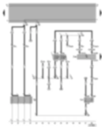
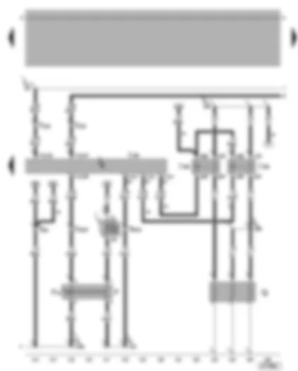
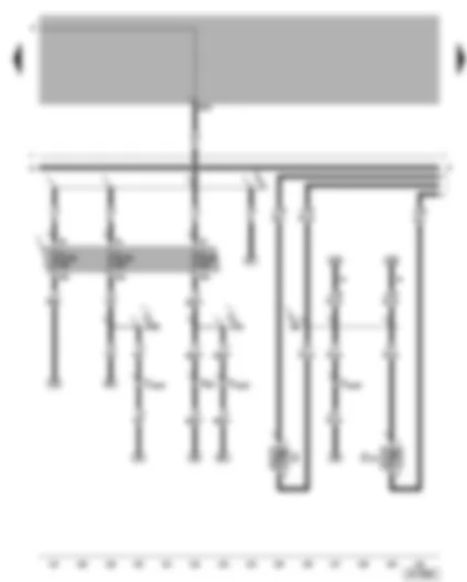
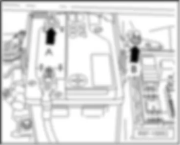
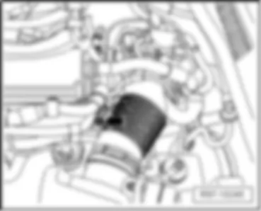
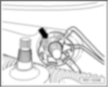
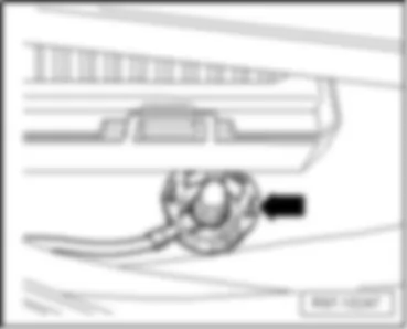
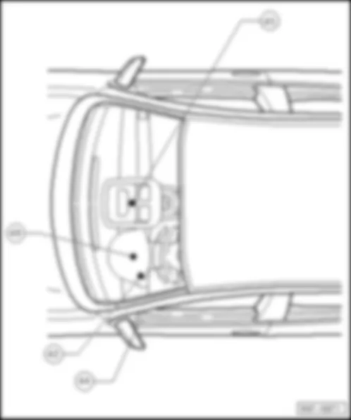
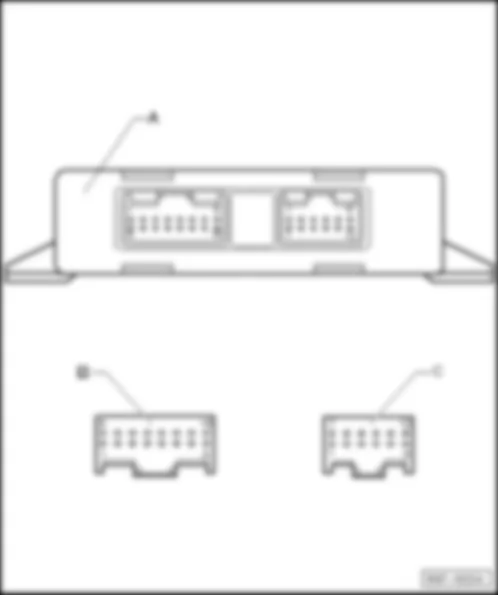
| A | Battery |
| B | Starter |
| C | Alternator |
| C1 | Voltage regulator |
| D | Ignition/starter switch |
| J4 | Dual tone horn relay |
| J59 | X contact relief relay |
| S162 | Fuse -1- (30), in fuse box/battery |
| S163 | Fuse -2- (30), in fuse box/battery |
| S176 | Fuse -4- (30), in fuse box/battery |
| S177 | Fuse -5- (30), in fuse box/battery |
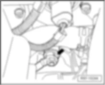
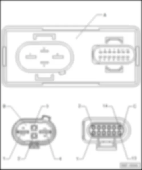
| T2e | 2-pin connector, near starter (only models without air conditioner) |
| T4 | 4-pin connector, near starter (only models with air conditioner) |
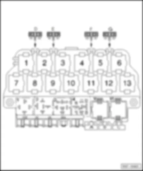
| T6 | 6-pin connector, brown, in control unit protective housing, in plenum chamber, left |
| 500 | Screw connection -1- (30), on relay plate |
| 502 | Screw connection -1- (30a), on relay plate |
| * | Only models with heater elements - coolant |
| ** | Up to August 2000 |
| -••- | From September 2000 |
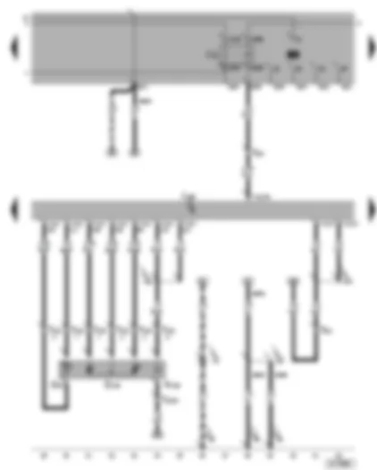
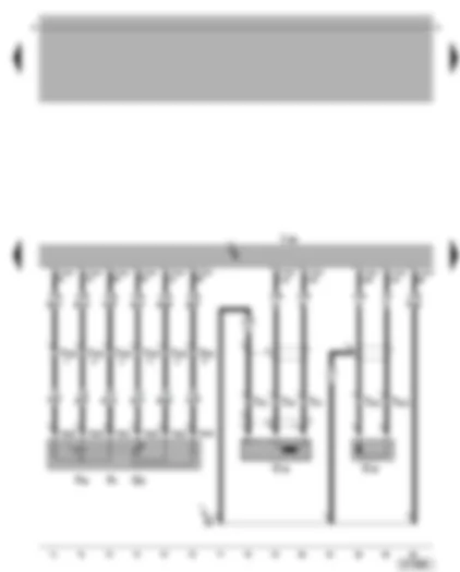
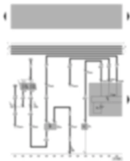
| D | Ignition/starter switch |
| J248 | Diesel direct injection system control unit, in plenum chamber, centre |
| J317 | Terminal 30 voltage supply relay, above the central electrics |
| Q6 | Glow plugs - engine |
| S10 | Fuse in fuse box |
| S229 | Fuse in fuse box |
| T2 | 2-pin connector, in cable channel left in engine compartment |
| T6 | 6-pin connector, brown, in control unit protective housing, in plenum chamber, left |
| T10h | 10-pin connector, blue, in control unit protective housing, in plenum chamber, left |
| T14a | 14-pin connector, near battery |
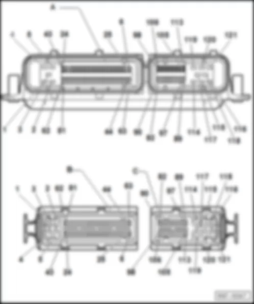
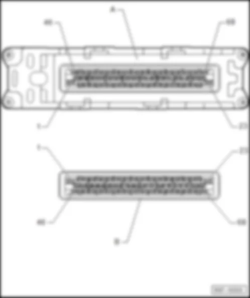
| T121 | 121-pin connector |
| 501 | Screw connection -2- (30), on relay plate |
| 504 | Screw connection -1- (87F), on relay plate |
| A2 | Positive (+) connection (15), in dash panel wiring harness |
| A32 | Positive (+) connection (30), in dash panel wiring harness |
| A80 | Connection -1- (X), in dash panel wiring harness |
| A98 | Positive (+) connection-4-(30), in dash panel wiring harness |
| A104 | Positive (+) connection -2- (15), in dash panel wiring harness |
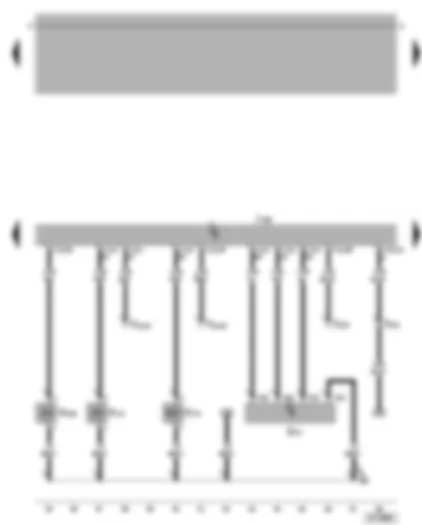
| G81 | Fuel temperature sender |
| G149 | Modulating piston movement sender |
| J52 | Glow plug relay |
| J248 | Diesel direct injection system control unit, in plenum chamber, centre |
| N146 | Metering adjuster |
| T6 | 6-pin connector, brown, in control unit protective housing, in plenum chamber, left |
| T10f | 10-pin connector, on engine front |
| T121 | 121-pin connector |
| |
| |
| 81 | Earth connection -1-, in dash panel wiring harness |
| 135 | Earth connection -2-, in dash panel wiring harness |
| D74 | Connection (86), in engine compartment wiring harness |
| F25 | Connection -1-, in diesel direct injection system wiring harness |
| *** | From May 2000 |
| -••- | Up to April 2000 |
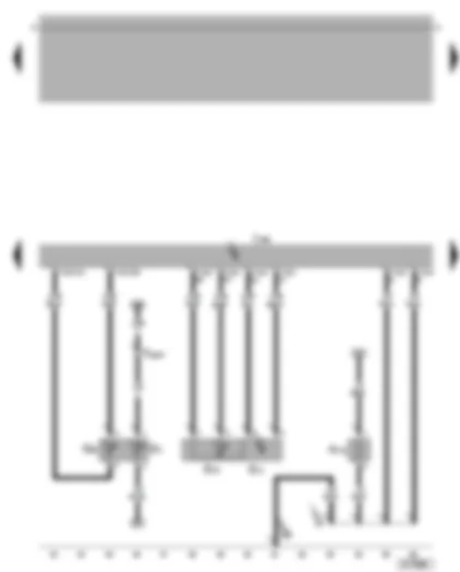
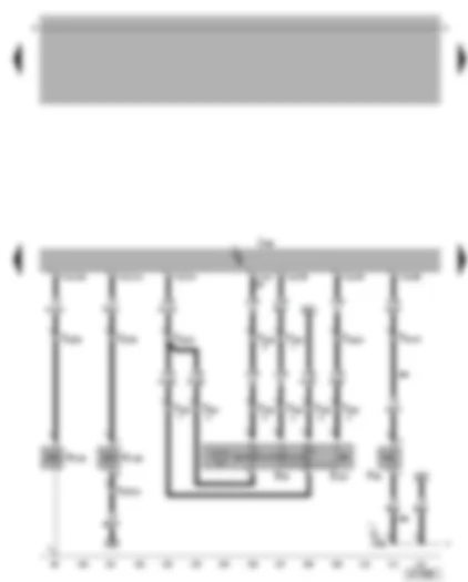
| G2 | Coolant temperature sender |
| G62 | Coolant temperature sender |
| G71 | Intake manifold pressure sender |
| G72 | Intake manifold temperature sender |
| J248 | Diesel direct injection system control unit, in plenum chamber, centre |
| N79 | Heater element (crankcase breather) |
| T14a | 14-pin connector, near battery |
| T121 | 121-pin connector |
| 131 | Earth connection -2-, in engine compartment wiring harness |
| |
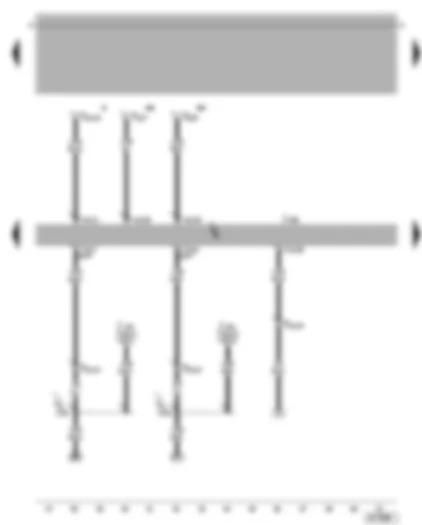
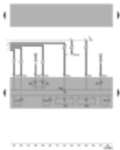
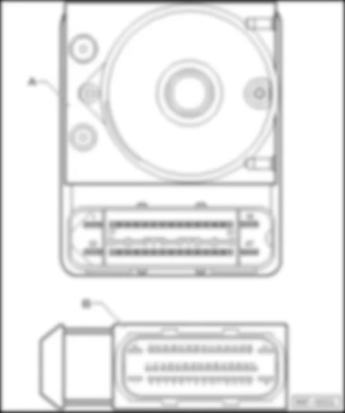
| J104 | ABS/ABS with EDL control unit |
| J248 | Diesel direct injection system control unit, in plenum chamber, centre |
| T10 | 10-pin connector, orange, in protective housing for connectors, in plenum chamber, left |
| T10w | 10-pin connector, white, in protective housing for connectors, in plenum chamber, left |
| T25 | 25-pin connector, on ABS/ABS with EDL control unit (up to July 2000) |
| T47a | 47-pin connector, ABS/ABS with EDL/TCS/ESP control unit (from August 2000) |
| T121 | 121-pin connector |
| A121 | Connection (high bus), in dash panel wiring harness |
| A122 | Connection (low bus), in dash panel wiring harness |
| * | Connection for radiator fan control unit/ radiator fan relay connection |
| ** | Connection for air conditioner |
| F8 | Kick-down switch |
| F60 | Idling switch |
| G28 | Engine speed sender |
| G79 | Accelerator pedal position sender |
| G80 | Needle lift sender |
| J248 | Diesel direct injection system control unit, in plenum chamber, centre |
| T2a | 2-pin connector, on engine front |
| T3 | 3-pin connector, on engine front |
| T6a | 6-pin connector |
| T10h | 10-pin connector, blue, in control unit protective housing, in plenum chamber, left |
| T121 | 121-pin connector |
| 200 | Earth connection (screening), in engine compartment wiring harness |
| G70 | Air mass meter |
| J248 | Diesel direct injection system control unit, in plenum chamber, centre |
| N18 | Exhaust gas recirculation valve |
| N75 | Charge pressure control solenoid valve |
| N239 | Intake manifold flap change-over valve |
| T5 | 5-pin connector |
| T10 | 10-pin connector, orange, in protective housing for connectors, in plenum chamber, left |
| T10w | 10-pin connector, white, in protective housing for connectors, in plenum chamber, left |
| T121 | 121-pin connector |
| E29 | Connection, in engine wiring harness |
| E45 | Cruise control system switch** |
| E227 | Cruise control system (CCS) button (Set)** |
| F36 | Clutch pedal switch** |
| J248 | Diesel direct injection system control unit, in plenum chamber, centre |
| N108 | Commencement of injection valve |
| N109 | Fuel shut-off valve |
| T10e | 10-pin connector, black, in control unit protective housing, in plenum chamber, left |
| T10f | 10-pin connector, on engine front |
| T10s | 10-pin connector, next to steering column |
| T10w | 10-pin connector, white, in protective housing for connectors, in plenum chamber, left |
| T121 | 121-pin connector |
| A155 | Connection -2- (86), in dash panel wiring harness |
| ** | Only models with CCS |
| F | Brake light switch |
| F47 | Cruise control system brake pedal switch (diesel direct injection system) |
| J248 | Diesel direct injection system control unit, in plenum chamber, centre |
| J359 | Low heat output relay*, in protective housing in engine compartment, left (53) |
| J360 | High heat output relay*, in protective housing in engine compartment, left (100) |
| Q7 | Coolant heating elements* |
| S13 | Fuse in fuse box |
| T6 | 6-pin connector, brown, in control unit protective housing, in plenum chamber, left |
| T10 | 10-pin connector, orange, in protective housing for connectors, in plenum chamber, left |
| T10e | 10-pin connector, black, in control unit protective housing, in plenum chamber, left |
| T121 | 121-pin connector |
| A18 | Connection (54), in dash panel wiring harness |
| A27 | Connection (speed signal), in dash panel wiring harness |
| A155 | Connection -2- (86), in dash panel wiring harness |
| D50 | Positive (+) connection (30), in engine compartment wiring harness |
| D98 | Connection (glow plugs), in engine compartment wiring harness |
| * | Only models with heater elements - coolant |
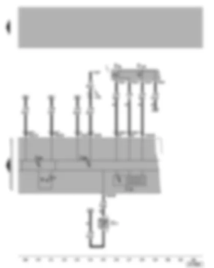
| G | Fuel gauge sender |
| G32 | Coolant shortage indicator sender |
| S232 | Fuse in fuse box |
| S234 | Fuse in fuse box |
| S243 | Fuse in fuse box |
| T6 | 6-pin connector, brown, in control unit protective housing, in plenum chamber, left |
| T14a | 14-pin connector, near battery |
| 269 | Earth connection (sender earth) -1-, in dash panel wiring harness |
| A71 | Connection (86), in dash panel wiring harness |
| A100 | Connection -2- (87), in dash panel wiring harness |
| B168 | Connection (86), in interior wiring harness |
| * | Only models with multi-function display |
| E86 | Multi-function display call-up button |
| E109 | Multi-function display, memory switch |
| G17 | Ambient temperature sensor |
| J119 | Multi-function display |
| J285 | Control unit with display in dash panel insert |
| J533 | Data bus diagnostic interface, in dash panel insert |
| K29 | Glow period warning lamp |
| T6e | 6-pin connector |
| T16 | 16-pin connector, in dash panel centre, self-diagnosis connection |
| T32 | 32-pin connector, blue |
| T32a | 32-pin connector, green |
| A76 | Connection (diagnosis wire K), in dash panel wiring harness |
| * | Only models with multi-function display |

