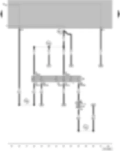
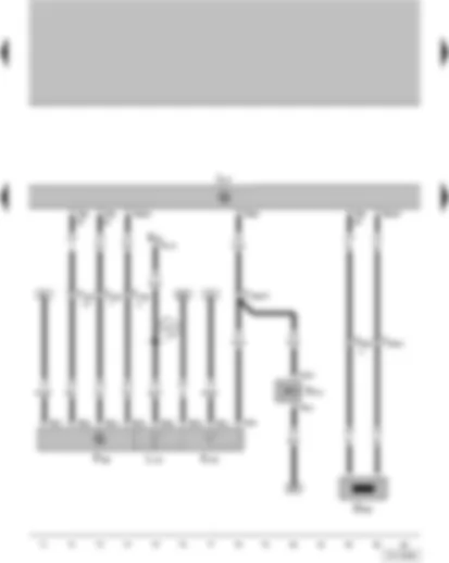
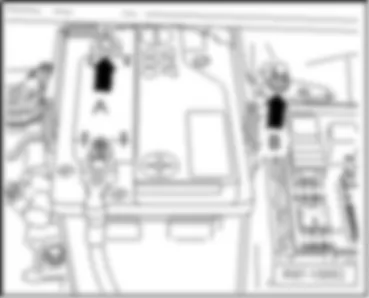
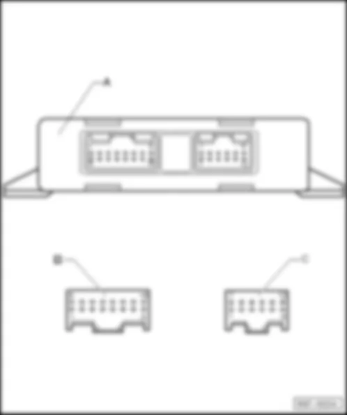
| A | Battery |
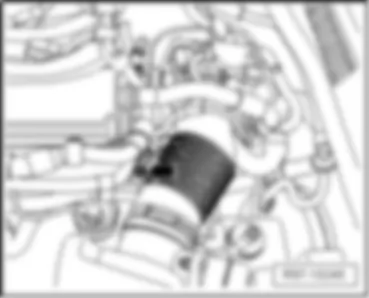
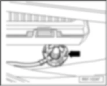
| B | Starter |
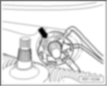
| C | Generator (GEN) |
| C1 | Voltage Regulator (VR) |
| J59 | Load Reduction Relay |
| S176 | Fuse 4 (30), in fuse bracket/battery |
| S177 | Fuse 5 (30), in fuse bracket/battery |
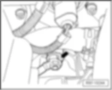
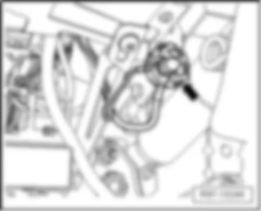
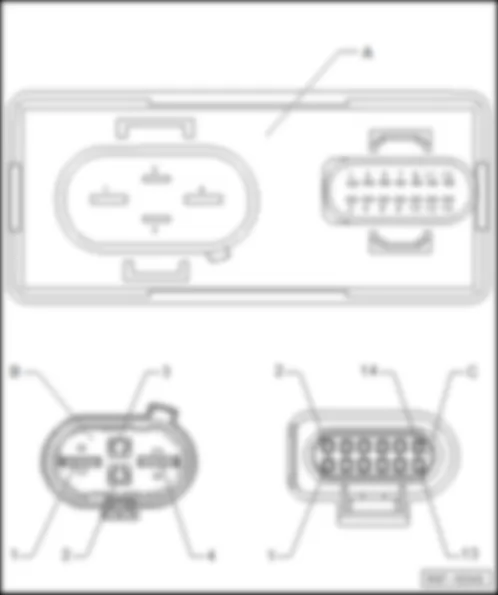
| T1a | Single connector, on starter |
| T2x | 2-pin connector, on generator (GEN) |
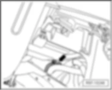
| T4 | 4-pin connector, near starter |
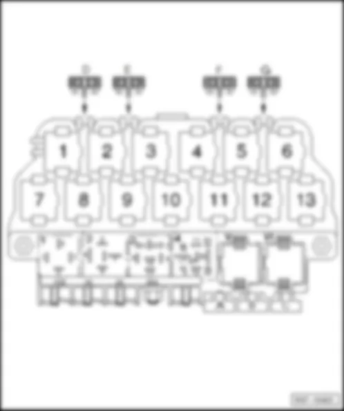
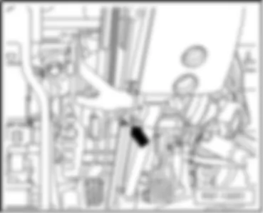
| T6 | 6-pin connector, brown, in the protection carcass for connectors, near water box, left |
| T10w | 10-pin connector, white, in the protection carcass for connectors, near water box, left |
| |
| |
| 500 | Threaded Connection 1 (30) on the relay plate |
| 503 | Bolted Connection (75x) (at relay panel) |
| 507 | Threaded Connection (30) (on relay holder/battery) |
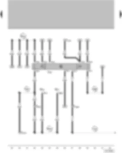
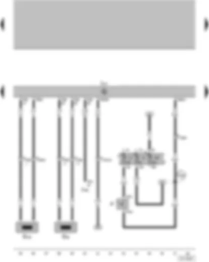
| J226 | Park/Neutral Position (PNP) Relay |
| M16 | Left Back-Up Light |
| M17 | Right Back-Up Light |
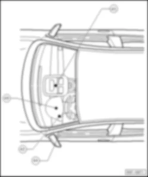
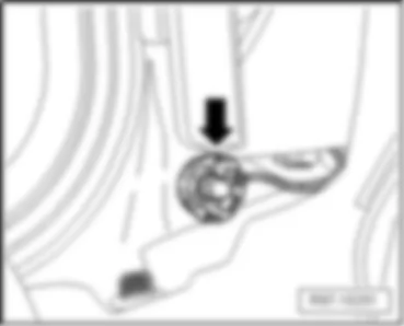
| T5h | 5-pin connector, on lower part of left A-pillar |
| T6g | 6-pin connector, on right Back-Up Light |
| T6h | 6-pin connector, on left Back-Up Light |
| T9 | 9-pin connector, on Park/Neutral Position (PNP) Relay |
| T10 | 10-pin connector, orange, in the protection carcass for connectors, near water box, left |
| T10g | 10-pin connector, in the protection carcass for connectors, near water box, left |
| 114 | Ground Connection, in automatic transmission wiring harness |
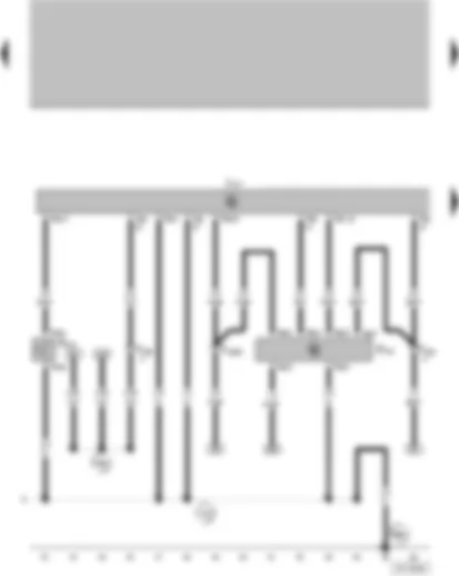
| A87 | Connection (reverse lamp), in instrument panel wiring harness |
| A98 | Plus Connection 4 (30), in instrument panel wiring harness |
| B163 | Plus Connection 4 (30), in instrument panel wiring harness |
| B182 | Connection (RF) in passenger compartment wiring harness |
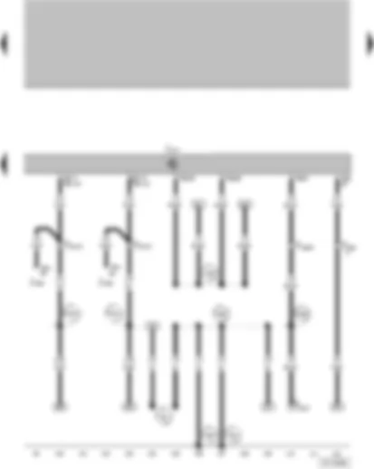
| F125 | Multi-Function Transmission Range (TR) Switch |
| F270 | Brake Pressure Switch |
| J217 | Transmission Control Module |
| T2cz | 2-pin connector, on brake pressure switch |
| T8a | 8-pin connector, on multi-Function Transmission Range (TR) Switch |
| T10g | 10-pin connector, in the protection carcass for connectors, near water box, left |
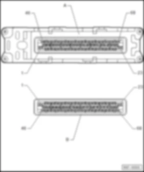
| T68 | 68-pin connector, on transmission Control Module |
| 114 | Ground Connection, in automatic transmission wiring harness |
| |
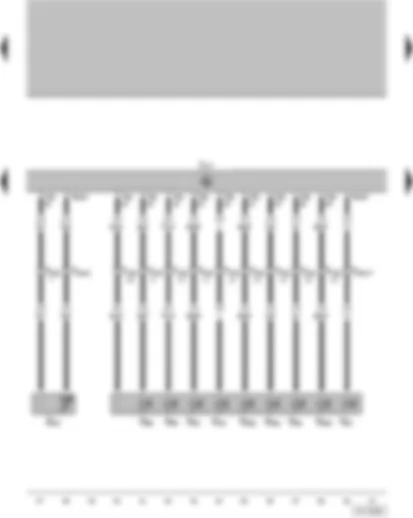
| A52 | Plus Connection 2 (30) (in instrument panel wiring harness) |
| E20 | Instrument Panel Light Dimmer Switch |
| F189 | Tiptronic Switch |
| G265 | Intermediate Shaft Speed Sensor |
| J217 | Transmission Control Module |
| K142 | Warning light for selector lever position P/N |
| L101 | Illumination for selector lever scale |
| N110 | Shift Lock Solenoid |
| T2a | 2-pin connector, on shift Lock Solenoid |
| T3c | 3-pin connector, on Instrument Panel Light Dimmer Switch |
| T8i | 8-pin connector, on Tiptronic switch |
| T10e | 10-pin connector, black, in the protection carcass for connectors, near water box, left |
| T10g | 10-pin connector, in the protection carcass for connectors, near water box, left |
| T20a | 20-pin connector, on solenoid valves |
| T68 | 68-pin connector, on transmission Control Module |
| A4 | Plus Connection (58b), in instrument panel wiring harness |
| F | Brake light switch |
| G68 | Vehicle Speed Sensor (VSS) |
| G182 | Sensor for transmission RPM |
| J217 | Transmission Control Module |
| J248 | Diesel Direct Fuel Injection (DFI) Engine Control Module |
| S13 | Fuse |
| S15 | Fuse |
| S239 | Fuse in fuse holder |
| T4f | 4-pin connector, on brake light switch |
| T10g | 10-pin connector, in the protection carcass for connectors, near water box, left |
| T10h | 10-pin connector, blue, in the protection carcass for connectors, near water box, left |
| T20a | 20-pin connector, on solenoid valves |
| T68 | 68-pin connector, on Transmission Control Module |
| T94 | 94-pin connector, on Diesel direct injection system control unit |
| A18 | Connection (54), in instrument panel wiring harness |
| J217 | Transmission Control Module |
| J248 | Diesel direct injection system control unit |
| T10g | 10-pin connector, in the protection carcass for connectors, near water box, left |
| T10w | 10-pin connector, white, in the protection carcass for connectors, near water box, left |
| T16 | 16-pin connector, auto-diagnosis connection |
| T68 | 68-pin connector, on automatic gearbox control unit |
| T94 | 94-pin connector, on Diesel direct injection system control unit |
| |
| |
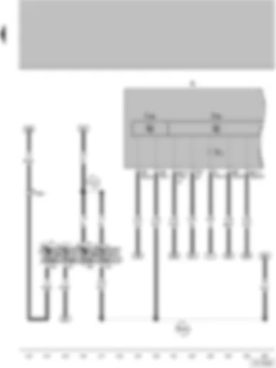
| 81 | Earth connection -1-, in dash panel wiring harness |
| 135 | Earth connection -2-, in dash panel wiring harness |
| A76 | Connection (K-diagnosis wire) in instrument panel wiring harness |
| A121 | Connection (High-Bus) in instrument panel wiring harness |
| A122 | Connection (Low-Bus) in instrument panel wiring harnes |
| U8 | Plus Connection (15a) (automatic transmission wiring harness) |
| J285 | Control Module with indicator unit in instrument panel insert |
| J533 | Data Bus On Board Diagnostic Interface |
| K | Instrument Cluster |
| K2 | Generator (GEN) Warning Light |
| S7 | Fuse |
| S11 | Fuse |
| S229 | Fuse in fuse holder |
| S231 | Fuse in fuse holder |
| T10g | 10-pin connector, in the protection carcass for connectors, near water box, left |
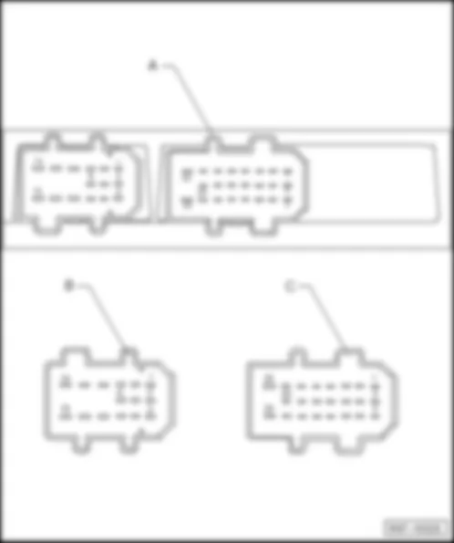
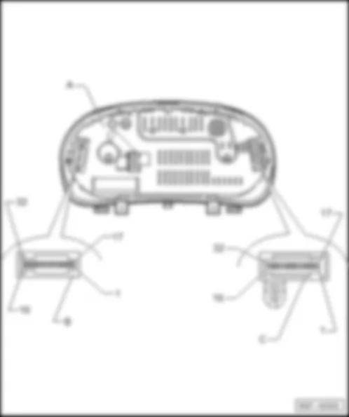
| T32 | 32-pin connector, blue, on instrument Cluster |
| T32a | 32-pin connector, green, on instrument Cluster |
| A2 | Plus Connection (15), in instrument panel wiring harness |
| B165 | Plus Connection 2 (15) in wiring harness interior |

