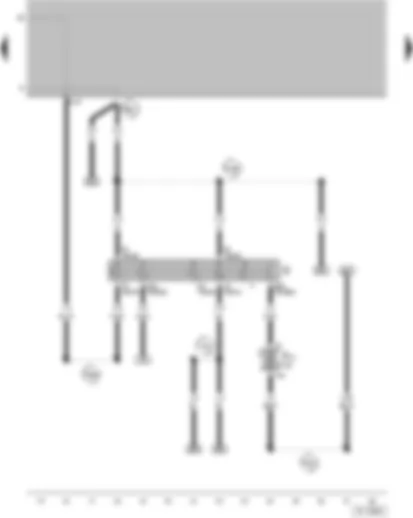
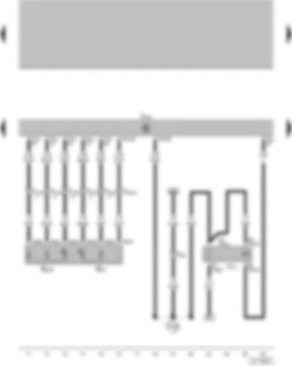
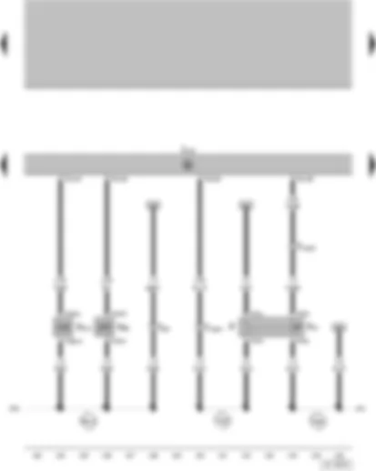
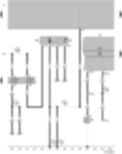
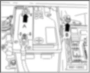
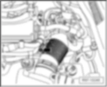
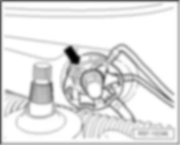
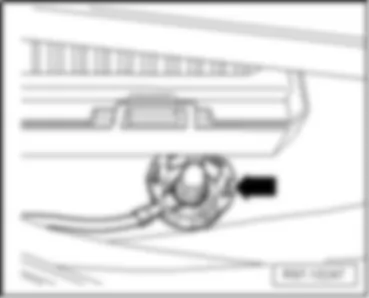
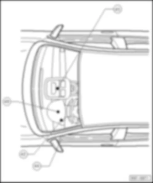
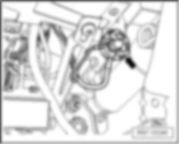
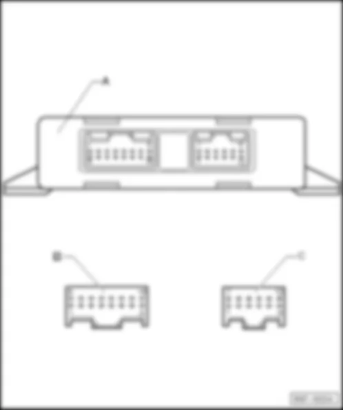
| A | Battery |
| B | Starter |
| C | Generator (GEN) |
| C1 | Voltage Regulator (VR) |
| J59 | Load Reduction Relay |
| S162 | Fuse 1 in fuse bracket/battery |
| S176 | Fuse 4 (30), in fuse bracket/battery |
| S177 | Fuse 5 (30), in fuse bracket/battery |
| T1a | Single connector, on starter |
| T2x | Double connector, on generator (GEN) |
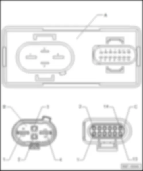
| T4 | 4-Pin connector, near generator (GEN) |
| T6 | 6-Pin connector |
| |
| |
| 500 | Threaded Connection 1 (30) on the relay plate |
| 503 | Bolted Connection (75x) (at relay panel) |
| 507 | Threaded Connection (30) (on relay holder/battery) |
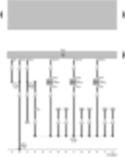
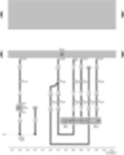
| J220 | Motronic Engine Control Module |
| N156 | Intake Manifold Change-Over Valve |
| N205 | Valve 1 for camshaft adjustment |
| N318 | Camshaft Adjustment Valve 1 (exhaust) |
| T2 | 2-pin connector, on left in luggage compartment |
| T2db | 2-pin connector, on valve 1 for camshaft adjustment |
| T2de | 2-pin connector, on camshaft Adjustment Valve 1 (exhaust) |
| T2df | 2-pin connector, on Intake Manifold Change-Over Valve |
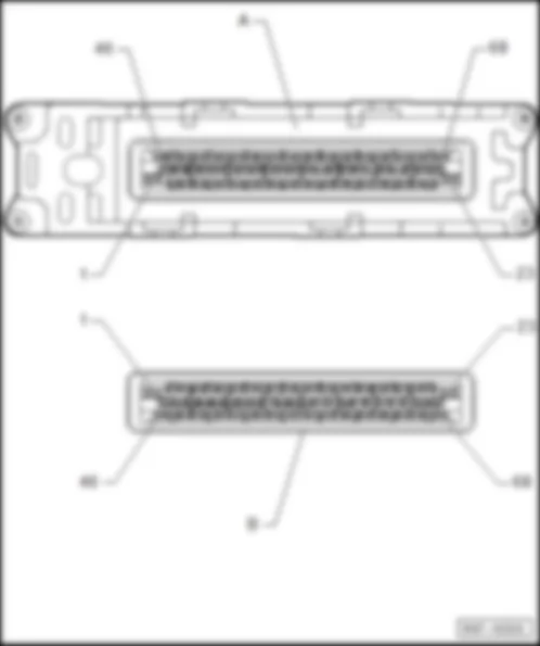
| T40 | 40-pin connector, on Motronic Engine Control Module |
| T81 | 81-pin connector, on Motronic Engine Control Module |
| 131 | Ground Connection 2, in engine compartment wiring harness |
| |
| D25 | Plus Connection (15), in basic engine harness |
| D52 | Plus Connection (15a), in engine compartment wiring harness |
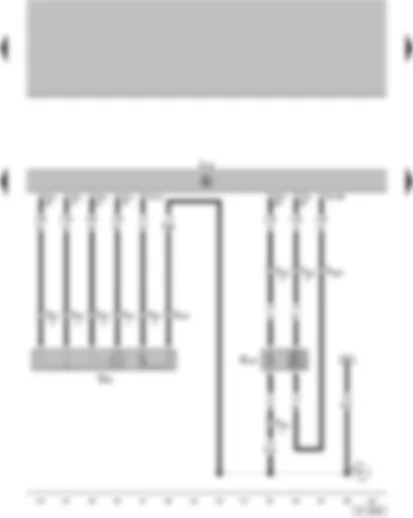
| G70 | Mass Air Flow (MAF) Sensor |
| J220 | Motronic Engine Control Module |
| T3ae | 3-pin connector, on Leak Detection Pump (LDP) |
| T5o | 5-pin connecotor, on Mass Air Flow (MAF) Sensor |
| T6 | 6-pin connector, brown, in the protection carcass for connectors, near water box, left |
| T10h | 10-pin connector, blue, in the protection carcass for connectors, near water box, left |
| T81 | 81-pin connector, on Motronic Engine Control Module |
| V144 | Leak Detection Pump (LDP) |
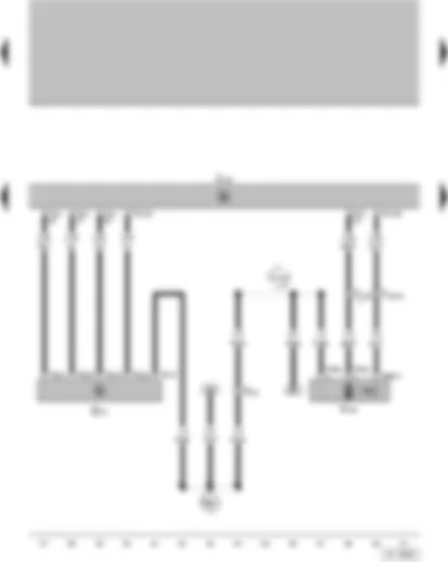
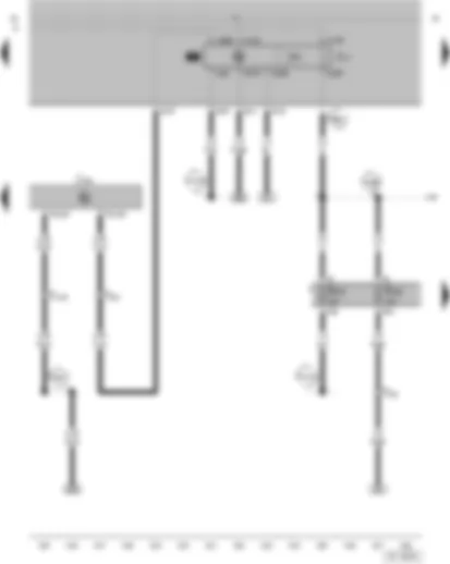
| A151 | Connection 4 (87) (in instrument panel wiring harness) |
| E30 | Connection (87a), in wiring harness engine |
| G79 | Throttle Position (TP) Sensor |
| G185 | Sender 2 for accelerator pedal position |
| J220 | Motronic Engine Control Module |
| J271 | Motronic Engine Control Module (ECM) Power Supply Relay |
| T5b | 5-pin connector, on Motronic Engine Control Module (ECM) Power Supply Relay |
| T6 | 6-pin connector, brown, in the protection carcass for connectors, near water box, left |
| T6b | 6-pin connector, on Throttle Position (TP) Sensor |
| T10h | 10-pin connector, blue, in the protection carcass for connectors, near water box, left |
| T81 | 81-pin connector, on Motronic Engine Control Module |
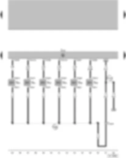
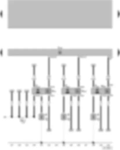
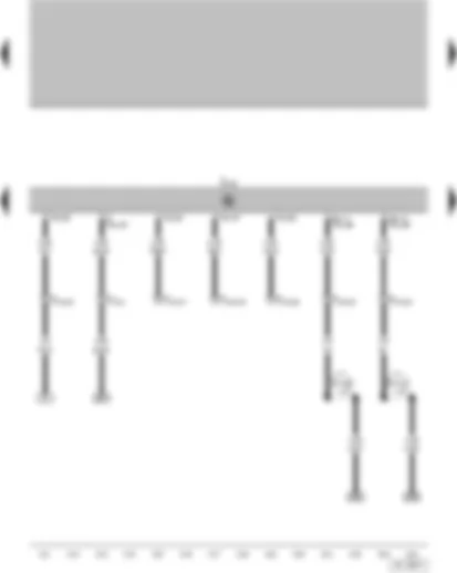
| D78 | Plus Connection 1 (30a), in engine compartment wiring harness |
| J220 | Motronic Engine Control Module |
| N30 | Cylinder 1 Fuel Injector |
| N31 | Cylinder 2 Fuel Injector |
| N32 | Cylinder 3 Fuel Injector |
| N33 | Cylinder 4 Fuel Injector |
| N83 | Cylinder 5 Fuel Injector |
| N84 | Cylinder 6 Fuel Injector |
| T2ab | 2-pin connector, on Cylinder 1 Fuel Injector |
| T2ac | 2-pin connector, on Cylinder 2 Fuel Injector |
| T2ad | 2-pin connector, on Cylinder 3 Fuel Injector |
| T2ae | 2-pin connector, on Cylinder 4 Fuel Injector |
| T2dg | 2-pin connector, on Cylinder 5 Fuel Injector |
| T2dh | 2-pin connector, on Cylinder 6 Fuel Injector |
| T14a | 14-pin connector, near battery |
| T40 | 40-pin connector, on Motronic Engine Control Module |
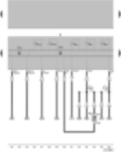
| A104 | Plus Connection 2 (15), in instrument panel wiring harness |
| D95 | Connection (injectors), in engine compartment wiring harness |
| G28 | Engine Speed (RPM) Sensor |
| G61 | Knock Sensor (KS) 1 |
| G66 | Knock Sensor (KS) 2 |
| J220 | Motronic Engine Control Module |
| T2av | 2-pin connector, on Knock Sensor (KS) 2 |
| T3af | 3-pin connector, on Knock Sensor (KS) 1 |
| T3ag | 3-pin connector, on Engine Speed (RPM) Sensor |
| T40 | 40-pin connector, on Motronic Engine Control Module |
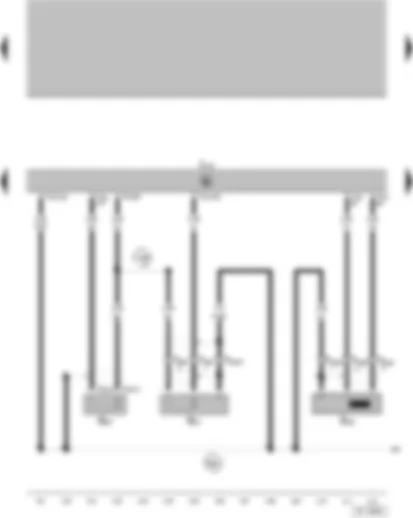
| 139 | Ground Connection (sensor Ground), in Motronic Multiport Fuel Injection (MFI) wiring harness |
| 220 | Ground Connection (sensor ground), in engine compartment wiring harness |
| G2 | Engine Coolant Temperature (ECT) Sensor |
| G40 | Camshaft Position (CMP) Sensor |
| G62 | Engine Coolant Temperature (ECT) Sensor |
| G163 | Camshaft Position (CMP) Sensor 2 |
| J220 | Motronic Engine Control Module |
| T3ah | 3-pin connector, on Camshaft Position (CMP) Sensor 2 |
| T3g | 3-pin connector, on Camshaft Position (CMP) Sensor |
| T4i | 4-pin connector, on Engine Coolant Temperature (ECT) Sensor |
| T10 | 10-pin connector, white in the protection carcass for connectors, near water box, left |
| T14a | 14-pin connector, near battery |
| T40 | 40-pin connector, on Motronic Engine Control Module |
| T81 | 81-pin connector, on Motronic Engine Control Module |
| 18 | Ground Connection, on engine block |
| 220 | Ground Connection (sensor ground), in engine compartment wiring harness |
| 281 | Ground Connection 1, in wiring harness engine pre-wiring |
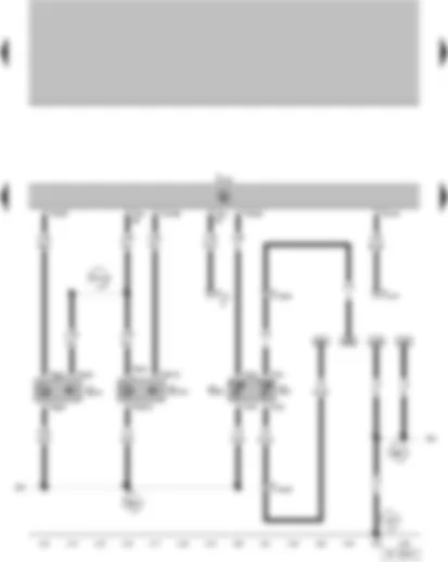
| D101 | Connection 1, in engine compartment wiring harness |
| J220 | Motronic Engine Control Module |
| N70 | Ignition Coil 1 with Power Output Stage |
| N127 | Ignition Coil 2 with Power Output Stage |
| N291 | Ignition Coil 3 with Power Output Stage |
| P | Spark Plug Connectors |
| Q | Spark Plugs |
| T4o | 4-pin connector, on Ignition Coil 1 with Power Output Stage |
| T4p | 4-pin connector, on Ignition Coil 2 with Power Output Stage |
| T4q | 4-pin connector, on Ignition Coil 3 with Power Output Stage |
| T40 | 40-pin connector, on Motronic Engine Control Module |
| 281 | Ground Connection 1, in wiring harness engine pre-wiring |
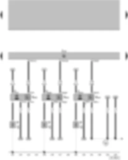
| J220 | Motronic Engine Control Module |
| N292 | Ignition Coil 4 with Power Output Stage |
| N323 | Ignition Coil 5 with Power Output Stage |
| N324 | Ignition Coil 6 with Power Output Stage |
| P | Spark Plug Connectors |
| Q | Spark Plugs |
| T4r | 4-pin connector, on Ignition Coil 4 with Power Output Stage |
| T4ag | 4-pin connector, on Ignition Coil 5 with Power Output Stage |
| T4ah | 4-pin connector, on Ignition Coil 6 with Power Output Stage |
| T40 | 40-pin connector, on Motronic Engine Control Module |
| 85 | Ground Connection 1, in engine compartment wiring harness |
| J220 | Motronic Engine Control Module |
| J293 | Coolant Fan Control (FC)Control Module |
| N79 | Positive Crankcase Ventilation (PCV) Heating Element |
| T2di | 2-pin connector, on Positive Crankcase Ventilation (PCV) Heating Element |
| T2dj | 2-pin connector, on After-Run Coolant Pump |
| T6 | 6-pin connector, brown, in the protection carcass for connectors, near water box, left |
| T14 | 14-pin connector, on Coolant Fan Control (FC)Control Module |
| T14a | 14-pin connector, near battery |
| T81 | 81-pin connector, on Motronic Engine Control Module |
| V51 | After-Run Coolant Pump |
| 85 | Ground Connection 1, in engine compartment wiring harness |
| |
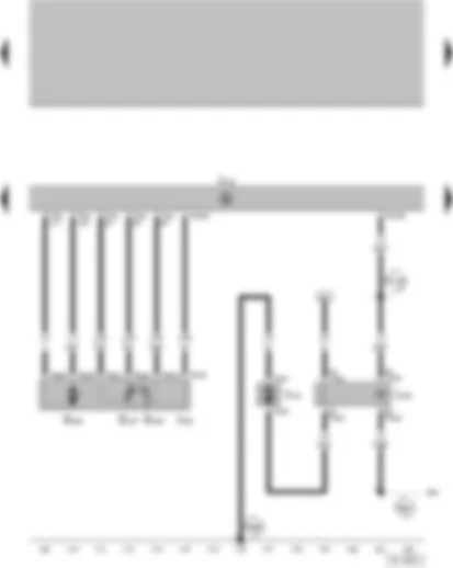
| D136 | Plus Connection 2 (15a) in wiring harness engine compartment |
| G186 | Throttle drive (power accelerator actuation) |
| G187 | Angle sensor 1 for throttle drive (power accelerator actuation) |
| G188 | Angle sensor 2 for throttle drive (power accelerator actuation) |
| J220 | Motronic Engine Control Module |
| J299 | Secondary Air Injection (AIR) Pump Relay |
| J338 | Throttle Valve Control Module |
| T2c | 2-pin connector, on Secondary Air Injection (AIR) Pump Motor |
| T4k | 4-pin connector, on Secondary Air Injection (AIR) Pump Relay |
| T6a | 6-pin connector, on Throttle Valve Control Module |
| T40 | 40-pin connector, on Motronic Engine Control Module |
| T81 | 81-pin connector, on Motronic Engine Control Module |
| V101 | Secondary Air Injection (AIR) Pump Motor |
| |
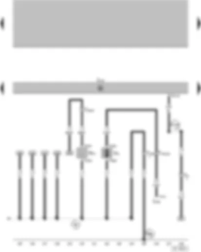
| D103 | Connection 3, in engine compartment wiring harness |
| E32 | Connection (87), in wiring harness Motronic |
| F | Brake Light Switch |
| F47 | Brake Pedal Switch |
| J220 | Motronic Engine Control Module |
| N80 | Evaporative Emission (EVAP) Canister Purge Regulator Valve |
| N112 | Secondary Air Injection (AIR) Solenoid Valve |
| T2af | 2-pin connector, on Evaporative Emission (EVAP) Canister Purge Regulator Valve |
| T2be | 2-pin connector, on Secondary Air Injection (AIR) Solenoid Valve |
| T4f | 4-pin connector, on Brake Pedal Switch |
| T6 | 6-pin connector, brown, in the protection carcass for connectors, near water box, left |
| T10e | 10-pin connector, black, in the protection carcass for connectors, near water box, left |
| T81 | 81-pin connector, on Motronic Engine Control Module |
| A18 | Connection (54), in instrument panel wiring harness |
| A20 | Plus Connection (15a) (in instrument panel wiring harness) |
| E32 | Connection (87), in wiring harness Motronic |
| E45 | Cruise Control Switch |
| E227 | Cruise Control -SET- Button |
| F36 | Clutch Pedal Switch |
| J220 | Motronic Engine Control Module |
| T4u | 4-pin connector, on Clutch Pedal Switch |
| T10e | 10-pin connector, black, in the protection carcass for connectors, near water box, left |
| T10s | 10-pin connector, near Cruise Control -SET- Button |
| T10w | 10-pin connector, white in the protection carcass for connectors, near water box, left |
| T81 | 81-pin connector, on Motronic Engine Control Module |
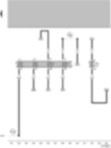
| A20 | Plus Connection (15a) (in instrument panel wiring harness) |
| J17 | Fuel Pump (FP) Relay |
| J220 | Motronic Engine Control Module |
| S232 | Fuse in fuse holder |
| S243 | Fuse in fuse holder |
| T6 | 6-pin connector, brown, in the protection carcass for connectors, near water box, left |
| T10 | 10-pin connector, white in the protection carcass for connectors, near water box, left |
| T81 | 81-pin connector, on Motronic Engine Control Module |
| 504 | Threaded Connection 1 (87) on the relay plate |
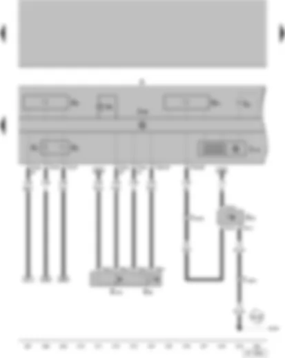
| A27 | Connection (vehicle speed signal), in instrument panel wiring harness |
| A99 | Connection 1 (87), in instrument panel wiring harness |
| A101 | Connection 3 (87), in instrument panel wiring harness |
| A125 | Connection (crash signal) in instrument panel wiring harness |
| F1 | Oil Pressure Switch |
| G | Sender for fuel gauge |
| G6 | Fuel Pump (FP) |
| J285 | Control Module with indicator unit in instrument panel insert |
| K | Instrument Cluster |
| S228 | Fuse in fuse holder |
| S234 | Fuse in fuse holder |
| T1b | Single connector, on oil pressure switch |
| T4h | 4-pin connector, on Fuel Pump (FP) |
| T14a | 14-pin connector, near battery |
| T16 | 16-pin connector, auto-diagnosis connection |
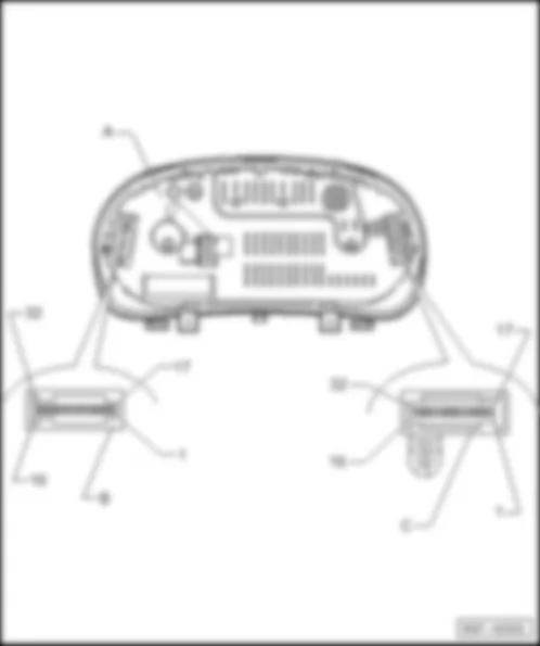
| T32 | 32-pin connector, on Instrument Cluster |
| |
| |
| 135 | Ground Connection 2, in instrument panel wiring harness |
| A76 | Connection (K-diagnosis wire) in instrument panel wiring harness |
| A99 | Connection 1 (87), in instrument panel wiring harness |
| A100 | Connection 2 (87), in instrument panel wiring harness |
| G32 | Engine Coolant Level (ECL) Sensor |
| J285 | Control Module with indicator unit in instrument panel insert |
| J533 | Data Bus On Board Diagnostic Interface |
| K | Instrument Cluster |
| K28 | Engine Coolant Level/Temperature (ECL/ECT) Warning Light |
| K31 | Cruise Control Indicator Light |
| K83 | Malfunction Indicator Lamp (MIL) |
| K105 | Low Fuel Level Warning Light |
| K132 | Electronic Power Control (EPC) Warning Lamp |
| T2dk | 2-pin connector, on Engine Coolant Level (ECL) Sensor |
| T32 | 32-pin connector, on Instrument Cluster |
| T32a | 32-pin connector, on Instrument Cluster |
| 269 | Ground Connection (sensor ground) 1, in instrument panel wiring harness |
| A13 | Connection (door contact switch) in instrument panel wiring harness |
| E86 | Multi-Function Indicator Mode Select Switch |
| E109 | Multi-Function Indicator Memory Switch |
| G1 | Fuel Gauge |
| G3 | Engine Coolant Temperature (ECT) Gauge |
| G5 | Tachometer |
| G21 | Speedometer |
| G22 | Speedometer Vehicle Speed Sensor (VSS) |
| H3 | Warning Buzzer |
| J119 | Multi-function Indicator (MFA) |
| J285 | Control Module with indicator unit in instrument panel insert |
| K | Instrument Cluster |
| K3 | Oil Pressure Warning Light |
| T3h | 3-pin connector, on Speedometer Vehicle Speed Sensor (VSS) |
| T6e | 6-pin connector, on Multi-Function Indicator Memory Switch |
| T14a | 14-pin connector, near battery |
| T32 | 32-pin connector, on Instrument Cluster |
| T32a | 32-pin connector, on Instrument Cluster |
| B163 | Plus Connection 1 (15) in wiring harness interior |

