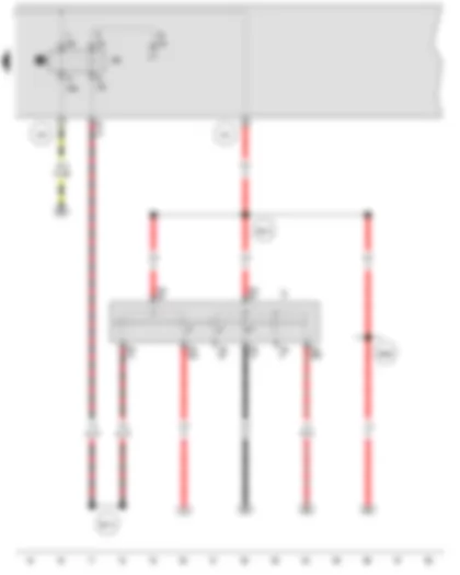
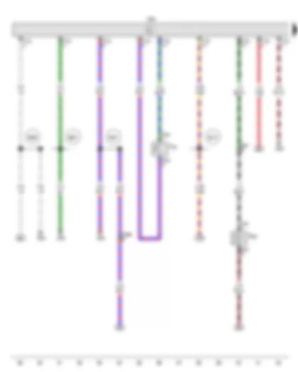
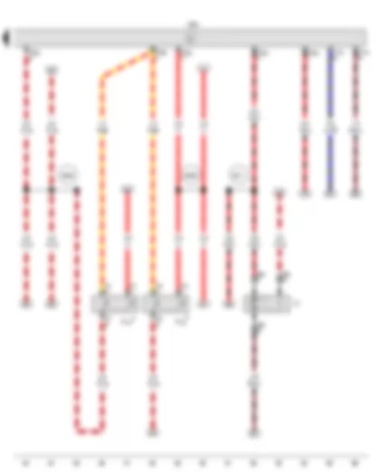
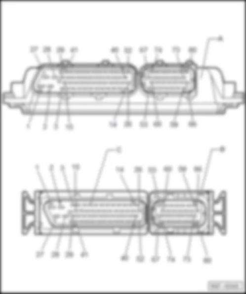
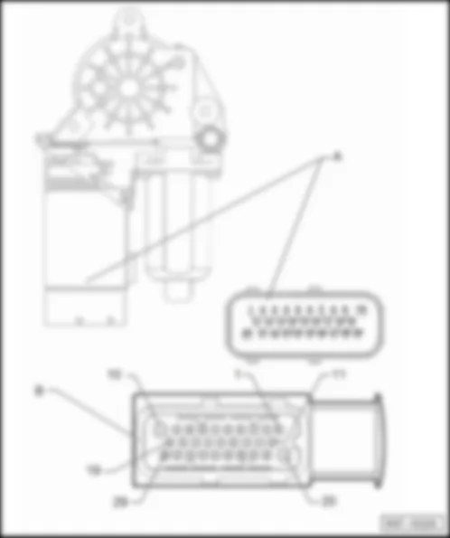
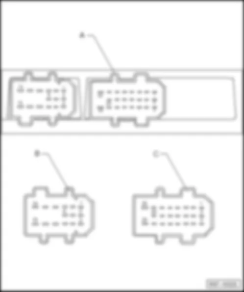
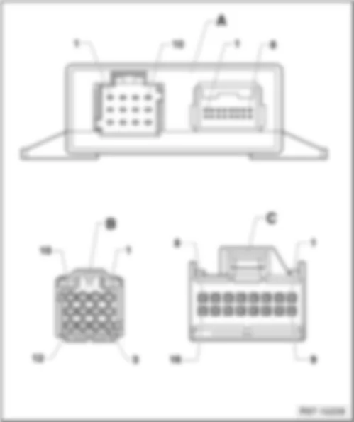
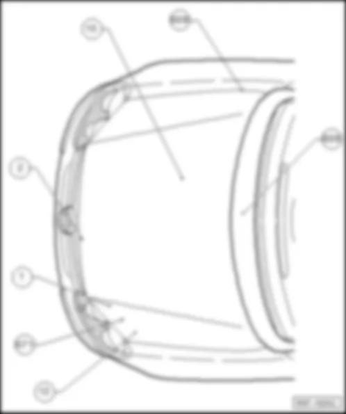
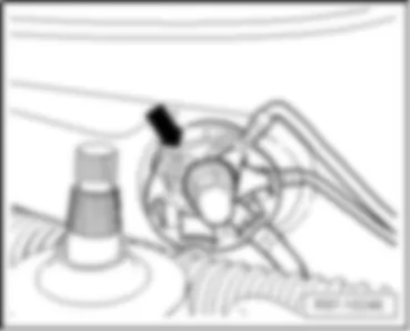
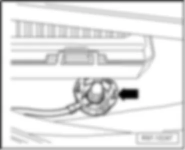
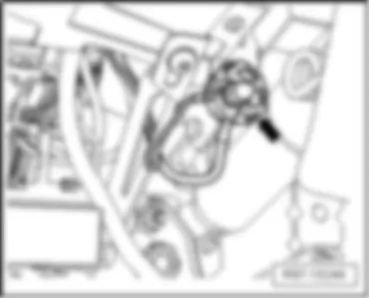
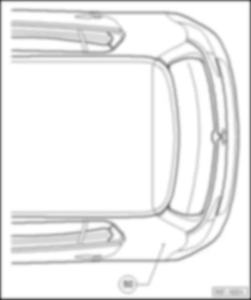
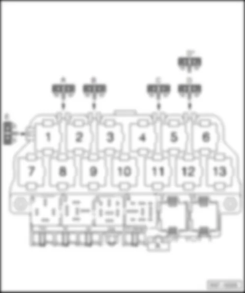
| Designation of connector: | | A - | Engine control unit -J623- | | B/C - | 80-pin connector, on engine control unit -T80a- |
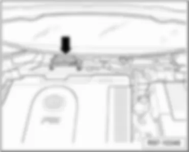
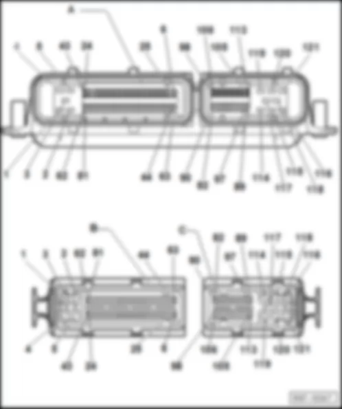
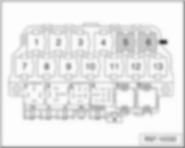
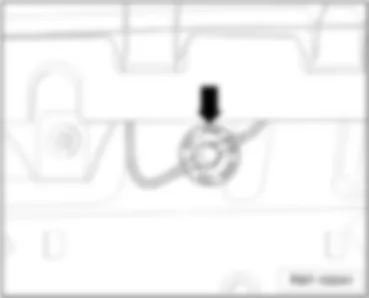
| – | Central under plenum chamber cover -Arrow- | | | | | Designation of connector: | | A - | Engine control unit -J623- | | B/C - | 121-pin connector, on engine control unit -T121a- |
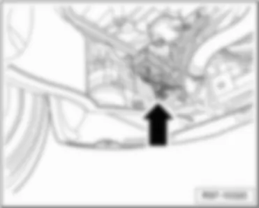
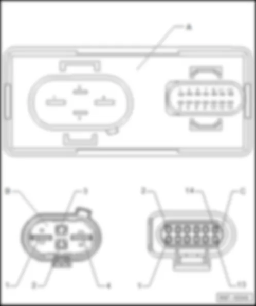
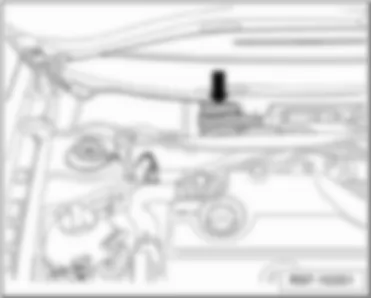
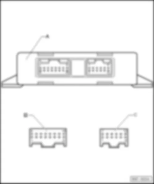
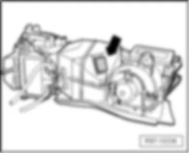
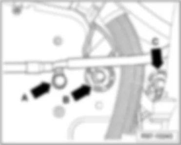
| – | in engine compartment, bottom left -arrow- | | | | | Designation of connector: | | A - | Radiator fan control unit -J293- | | B - | 4-pin connector, on radiator fan control unit -T4ag- | | C - | 14-pin connector, on radiator fan control unit -T14b- |
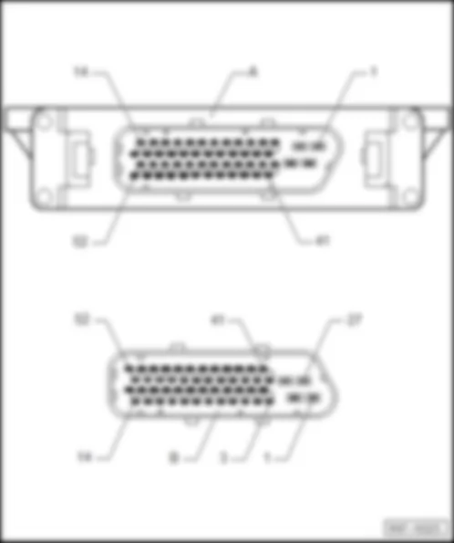
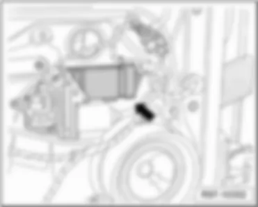
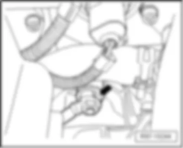
| – | in engine compartment, right -arrow- | | | | | Designation of connector: | | A - | Automatic gearbox control unit -J217- | | B - | 52-pin connector, on automatic transmission control unit -T52a- |
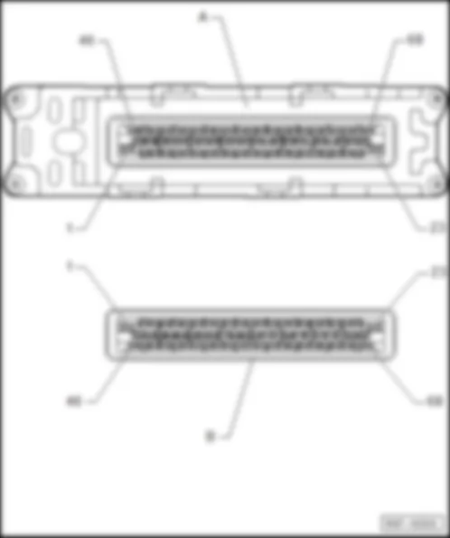
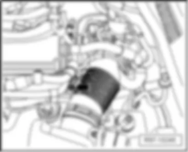
| – | in engine compartment, right -arrow- | | | | | Designation of connector: | | A - | Automatic gearbox control unit -J217- | | B - | 68-pin connector, on automatic transmission control unit -T68b- |
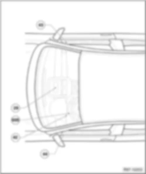
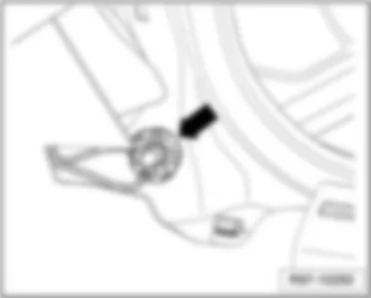
| – | behind the door trim, front left -arrow- | | | | | Designation of connector: | | A - | Driver door control unit -J386- | | B - | 29-pin connector, on driver door control unit -T29a- |
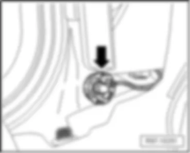
| – | behind the door trim, front right -arrow- | | | | | Designation of connector: | | A - | Front passenger door control unit -J387- | | B - | 29-pin connector, on front passenger door control unit -T29b- |
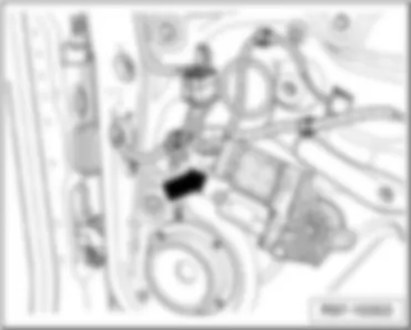
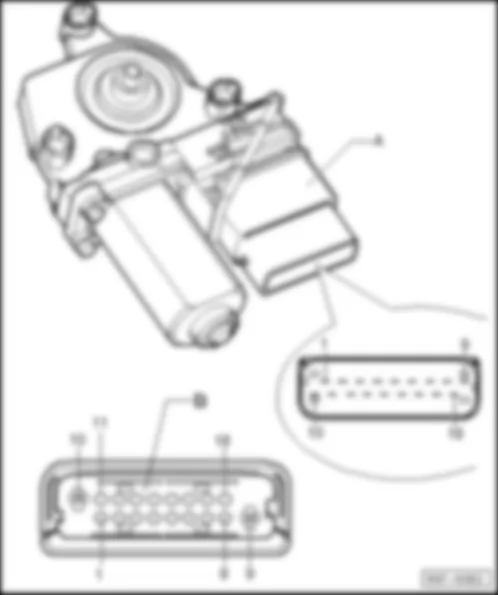
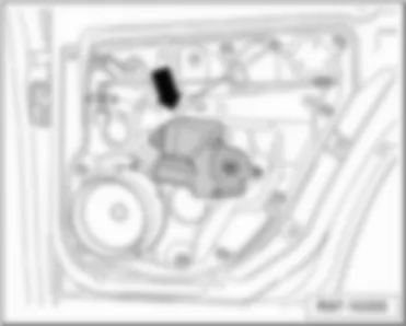
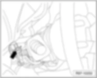
| – | behind the door trim, rear left -arrow- | | | | | Designation of connector: | | A - | Rear left door control unit -J388- | | B - | 18-pin connector, on left rear door control unit -T18c- |
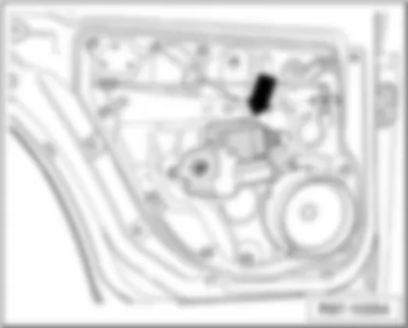
| – | behind the door trim, rear right -arrow- | | | | | Designation of connector: | | A - | Rear right door control unit -J389- | | B - | 18-pin connector, on left rear door control unit -T18d- |
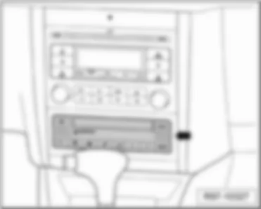
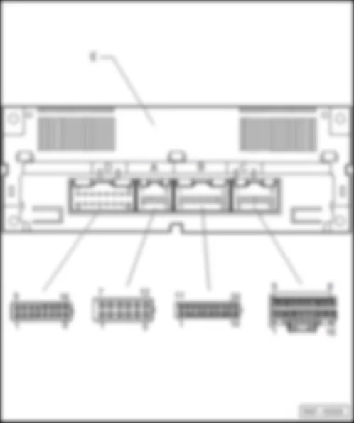
| – | In centre console, under radio -arrow- | | | | | Designation of connector: | | E - | Climatronic control unit -J255- | | A - | 12-pin connector, on Climatronic control unit -T12b- | | B - | 20-pin connector, on Climatronic control unit -T20a- | | C - | 16-pin connector, on Climatronic control unit -T16d- | | D - | 16-pin connector, on Climatronic control unit -T16b- |
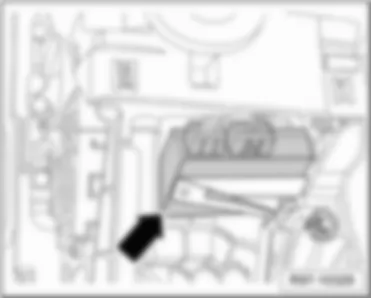
| – | Above relay plate-arrow- | | | | | Designation of connector: | | A - | Convenience system central control unit -J393- | | B - | 15-pin connector, on convenience system central control unit -T15a- | | C - | 23-pin connector, on convenience system central control unit -T23b- |
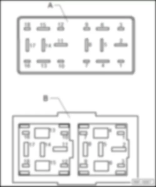
| – | on relay plate, dash panel, left -arrow- | | | | | Designation of connector: | | A - | Multifunction steering wheel control unit -J453- | | B - | 18-pin connector, on multi-function steering wheel control unit -T18b- |
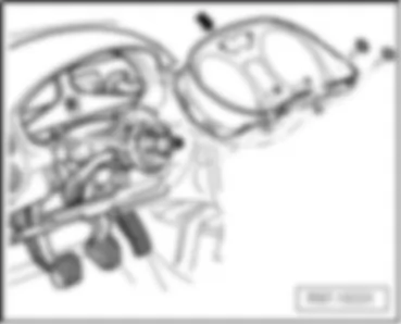
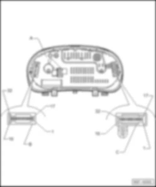
| – | on dash panel, left -arrow- | | | | | Designation of connector: | | A - | Control unit with display in dash panel insert -J285- | | C - | 32-pin connector, on control unit with display in dash panel insert -T32a- | | 7 - | Terminal 31, sensor earth | | 8 - | Coolant temperature indicator sensor | | 16 - | Rear lid release switch | | 17 - | Terminal 56a - high beam - | | 20 - | Terminal 58b - tail lights - | | 22 - | Coolant shortage indicator sender | | 25 - | Terminal K/W - engine diagnosis - | | 26 - | Terminal 58r - right parking light - | | 27 - | Terminal 58l - left parking light - | | 29 - | Brake fluid level warning contact | | 31 - | Front left belt switch | | B - | 32-pin connector, on control unit with display in dash panel insert -T32b- | | 2 - | Immobilizer reader coil | | 5 - | Terminal K/W - engine diagnosis - | | 6 - | Windscreen washer fluid level sender | | 8 - | Terminal for CAN-Bus "high" - convenience - | | 9 - | Terminal for CAN-Bus "low" - convenience - | | 12 - | Radiator fan control unit | | 13 - | Handbrake warning switch | | 17 - | Immobilizer reader coil | | 19 - | Terminal for CAN-Bus high | | 20 - | Terminal for CAN-Bus low | | 22 - | Contact switch on bonnet / bonnet for alarm system | | 23 - | Intermittent wiper regulator | | 24 - | Intermittent wiper regulator | | 25 - | Intermittent wiper regulator | | 26 - | Ambient temperature sensor | | 27 - | Terminal for CAN-Bus high | | 28 - | Terminal for CAN-Bus low |
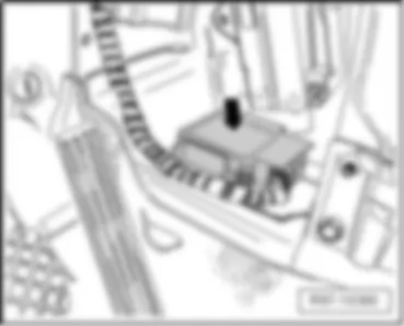
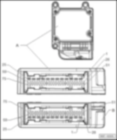
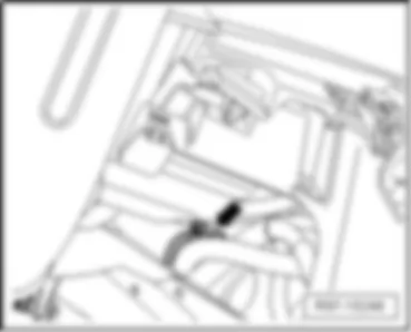
| – | under centre console -arrow- | | | | | Designation of connector: | | A - | Airbag control unit -J234- | | B - | 75-pin connector, on airbag control unit -T75a- |
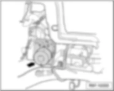
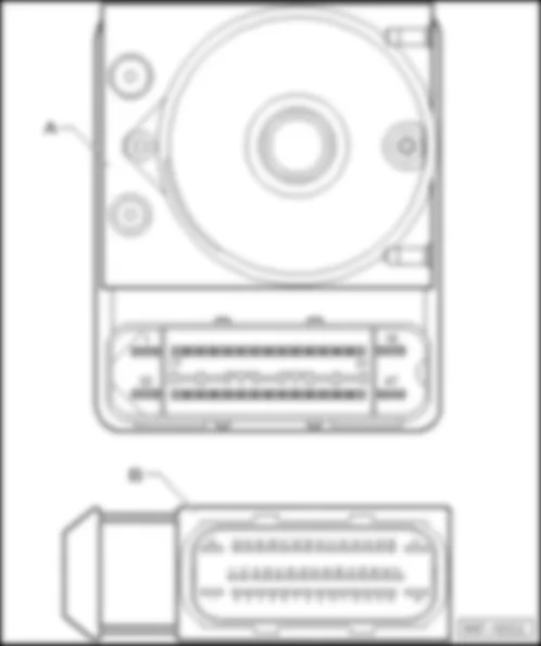
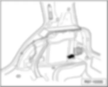
| – | In engine compartment, left -arrow- | | | | | Designation of connector: | | A - | ABS control unit -J104- | | B - | 47-pin connector, on ABS control unit -T47a- |
| – | Behind right luggage compartment lining-arrow- | | | | | Designation of connector: | | A - | Parking aid control unit -J446- | | B - | 16-pin connector, on parking aid control unit -T16e- | | C - | 12-pin connector, on parking aid control unit -T12d- |
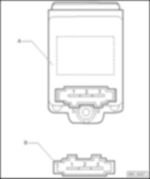
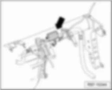
| – | Behind dashboard, right side, near glove compartment -arrow- | | | | | Designation of connector: | | A - | Fresh air blower control unit -J126- | | B - | 3-pin connector, on fresh air blower control unit -T3ad- |
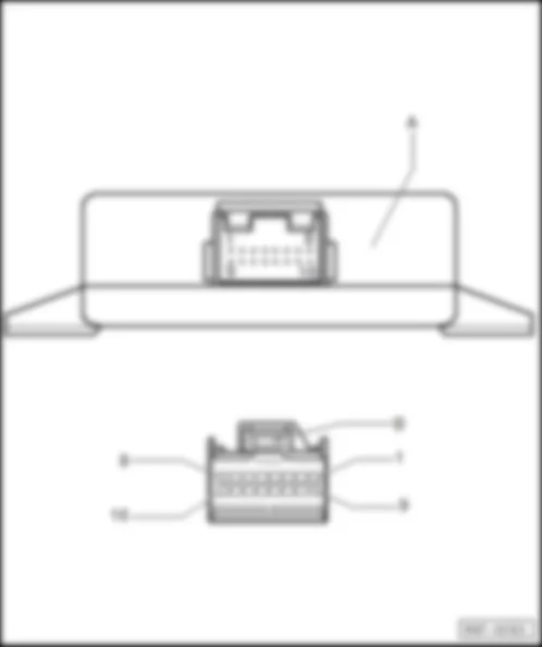
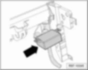
| – | behind the glove compartment -arrow- | | | | | Designation of connector: | | A - | Control unit for interactive system -J879- | | B - | 16-pin connector, on control unit for interactive system -T16f- |
| – | Above glove compartment -arrow- | | | | | Designation of connector: | | A - | Control unit for lighting and wiper functions -J917- | | B - | 12-pin connector, on control unit for lighting and wiper functions -T12h- | | C - | 16-pin connector, on control unit for lighting and wiper functions -T16g- |
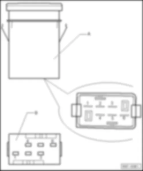
| – | At centre of dashboard -arrow- | | | | | Designation of connector: | | A - | Heated driver seat control unit -J131- | | B - | 6-pin connector, on heated driver seat control unit -T6p- |
| – | At centre of dashboard -arrow- | | | | | Designation of connector: | | A - | Heated front passenger seat control unit -J132- | | B - | 6-pin connector, on heated front passenger seat control unit -T6q- |
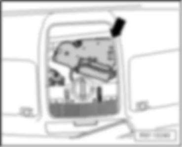
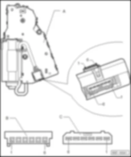
| – | near interior mirror, on roof-arrow- | | | | | Designation of connector: | | A - | Sliding sunroof adjustment control unit -J245- | | B - | 6-pin connector, on sliding sunroof adjustment control unit -T6m- | | C - | 6-pin connector, on control for sliding sunroof adjustment -T6v- |
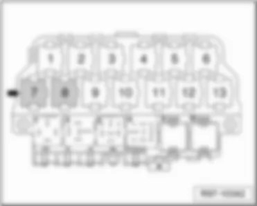
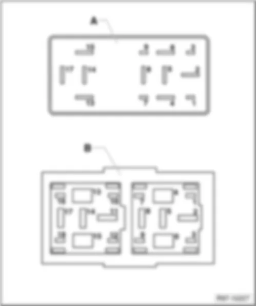
| – | on relay plate, dash panel, left -arrow- | | | | | Designation of connector: | | A - | Mirror memory control unit -J267- | | B - | 18-pin connector, on mirror memory control unit -T18e- |
|

