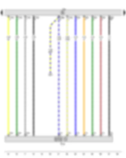
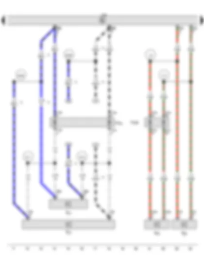
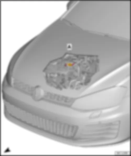
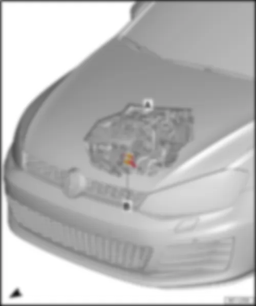
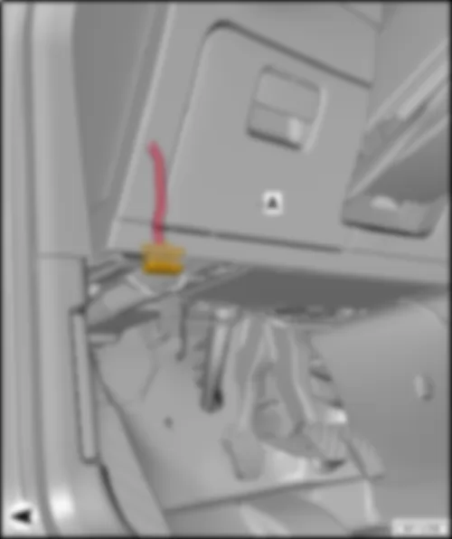
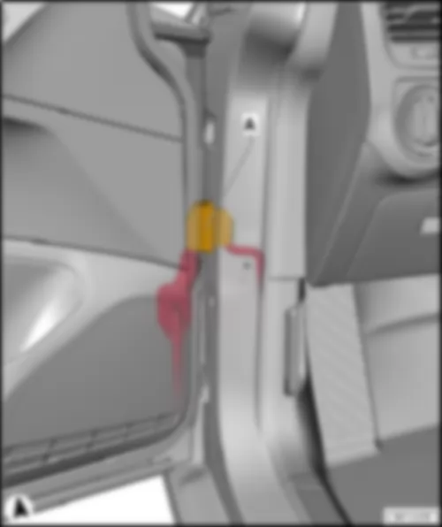
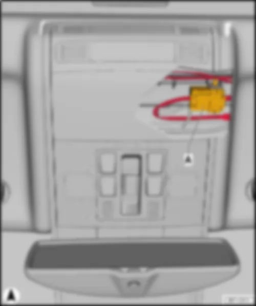
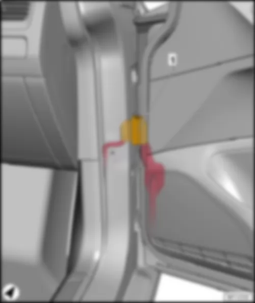
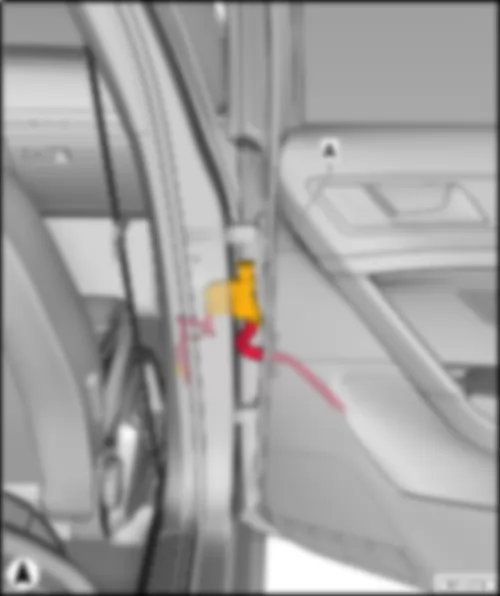
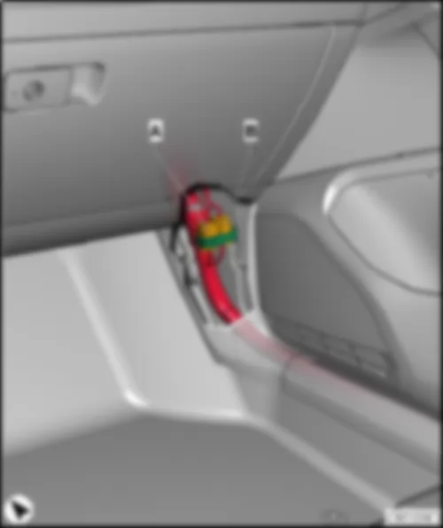
Wiring Diagram VW GOLF 2014 - Multimedia system operating unit - Display unit for front information display and operating unit control unit - Control unit 1 for information electronics - Fuse holder C
| E380 | Multimedia system operating unit |
| J525 | Digital sound package control unit |
| J685 | Display unit for front information display and operating unit control unit |
| J794 | Control unit 1 for information electronics |
| SC | Fuse holder C |
| SC10 | Fuse 10 on fuse holder C |
| SC12 | Fuse 12 on fuse holder C |
| SC16 | Fuse 16 on fuse holder C |
| T5ad | 5-pin connector, black |
| T5ah | 5-pin connector, grey |
| T8aq | 8-pin connector, black |
| T12ai | 12-pin connector, black |
| T12al | 12-pin connector, grey |
| T38 | 38-pin connector, black |
| 43 | Earth point, lower part of right A-pillar |
| 256 | Earth connection 2, in radio wiring harness |
| A167 | Positive connection 3 (30a) in dash panel wiring harness |
| B169 | Positive connection 1 (30), in interior wiring harness |
| * | According to equipment |
| *2 | Only models with amplifier |
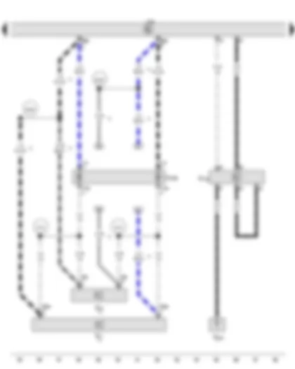
Wiring Diagram VW GOLF 2014 - Control unit 1 for information electronics - Connection for external audio sources
| J794 | Control unit 1 for information electronics |
| R199 | Connection for external audio sources |
| T4cm | 4-pin connector, black |
| T5ae | 5-pin connector, yellow |
| T7b | 7-pin connector, white |
| T12ag | 12-pin connector, green |
| * | According to equipment |
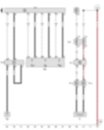
Wiring Diagram VW GOLF 2014 - Control unit 1 for information electronics - Interface for external multimedia unit
| J794 | Control unit 1 for information electronics |
| R215 | Interface for external multimedia unit |
| T5ae | 5-pin connector, yellow |
| T5d | 5-pin connector, green |
| T12ag | 12-pin connector, green |
| T16v | 16-pin connector, brown |
| 476 | Earth connection in audio wiring harness |
| 477 | Earth connection (audio), in main wiring harness |
| 482 | Earth connection 2 (audio), in main wiring harness |
| * | According to equipment |
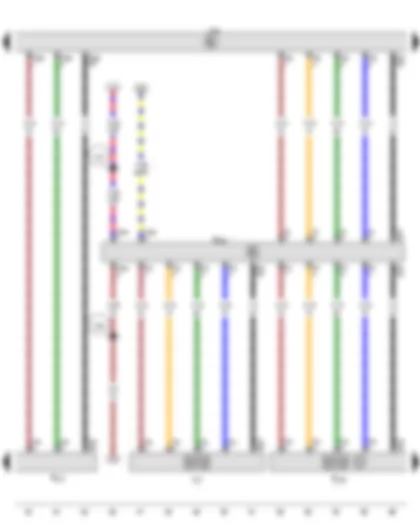
Wiring Diagram VW GOLF 2014 - Control unit 1 for information electronics - Connection for external audio sources - Interface for external multimedia unit - USB hub - USB charging socket 1
| J794 | Control unit 1 for information electronics |
| R199 | Connection for external audio sources |
| R215 | Interface for external multimedia unit |
| R293 | USB hub |
| T4ae | 4-pin connector, red |
| T5 | 5-pin connector, green |
| T5ae | 5-pin connector, yellow |
| T5d | 5-pin connector, green |
| T5h | 5-pin connector, green |
| T5r | 5-pin connector, purple |
| T5s | 5-pin connector, yellow |
| T5y | 5-pin connector, green |
| T5z | 5-pin connector, blue |
| U37 | USB charging socket 1 |
| 255 | Earth connection 1, in radio wiring harness |
| V32 | Positive connection (30), in telephone wiring harness |
| * | According to equipment |
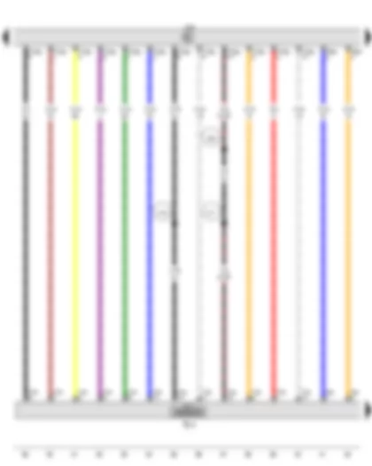
Wiring Diagram VW GOLF 2014 - Data bus diagnostic interface - Control unit 1 for information electronics - Front left treble loudspeaker - Front left bass loudspeaker - Telephone microphone - Connection for external audio sources
| J533 | Data bus diagnostic interface |
| J794 | Control unit 1 for information electronics |
| R20 | Front left treble loudspeaker |
| R21 | Front left bass loudspeaker |
| R38 | Telephone microphone |
| R199 | Connection for external audio sources |
| T2ei | 2-pin connector, black |
| T2r | 2-pin connector, black |
| T4aa | 4-pin connector, black |
| T4s | 4-pin connector, black |
| T8ar | 8-pin connector, brown |
| T12a | 12-pin connector, blue |
| T12ag | 12-pin connector, green |
| T12al | 12-pin connector, grey |
| T20 | 20-pin connector, red |
| T27 | 27-pin connector, black |
| T27b | 27-pin connector, black |
| TTVL | Coupling point on front left door |
| A178 | Connection (infotainment CAN bus, high), in dash panel wiring harness |
| A179 | Connection (infotainment CAN bus, low), in dash panel wiring harness |
| V8 | Connection (negative, front left loudspeaker), in loudspeaker wiring harness |
| V46 | Connection (front left loudspeaker), in loudspeaker wiring harness |
| V54 | Connection 1 (telephone), in main wiring harness |
| V55 | Connection 2 (telephone), in main wiring harness |
| V56 | Connection 3 (telephone), in main wiring harness |
| V57 | Connection 4 (telephone), in main wiring harness |
| * | Pre-wired component |
| *2 | According to equipment |
Wiring Diagram VW GOLF 2014 - Control unit 1 for information electronics - Rear left treble loudspeaker - Rear left bass loudspeaker - Front right treble loudspeaker - Front right bass loudspeaker
| J794 | Control unit 1 for information electronics |
| R14 | Rear left treble loudspeaker |
| R15 | Rear left bass loudspeaker |
| R22 | Front right treble loudspeaker |
| R23 | Front right bass loudspeaker |
| T2m | 2-pin connector, black |
| T2t | 2-pin connector, black |
| T4ad | 4-pin connector, black |
| T4r | 4-pin connector, black |
| T8ar | 8-pin connector, brown |
| T19b | 19-pin connector, black |
| T19c | 19-pin connector, black |
| T27a | 27-pin connector, black |
| T27c | 27-pin connector, black |
| TTHL | Coupling point on rear left door |
| TTVR | Coupling point on front right door |
| B195 | Connection (positive, rear left loudspeaker), in interior wiring harness |
| B196 | Connection (negative, rear left loudspeaker), in interior wiring harness |
| R71 | Connection (positive, loudspeaker)), in rear left door wiring harness |
| R72 | Connection (negative, loudspeaker), in rear left door wiring harness |
| V9 | Connection (positive, front right loudspeaker), in loudspeaker wiring harness |
| V10 | Connection (negative, front right loudspeaker), in loudspeaker wiring harness |
| * | According to equipment |
| *2 | Only models with 2-doors |
Wiring Diagram VW GOLF 2014 - Control unit 1 for information electronics - Rear right treble loudspeaker - Rear right bass loudspeaker - Right aerial module - Radio aerial
| J794 | Control unit 1 for information electronics |
| R16 | Rear right treble loudspeaker |
| R17 | Rear right bass loudspeaker |
| R109 | Right aerial module, Rear window, top right |
| R248 | Radio aerial |
| T2o | 2-pin connector |
| T4ac | 4-pin connector |
| T8ar | 8-pin connector, brown |
| T19 | 19-pin connector |
| T19a | 19-pin connector |
| TTHR | Coupling point on rear right door |
| B193 | Connection (positive, rear right loudspeaker), in interior wiring harness |
| B194 | Connection (negative, rear right loudspeaker), in interior wiring harness |
| R73 | Connection (positive, loudspeaker)), in rear right door wiring harness |
| R74 | Connection (negative, loudspeaker), in rear right door wiring harness |
| * | Rear window aerial |
| *2 | According to equipment |
| *3 | Only models with 2-doors |
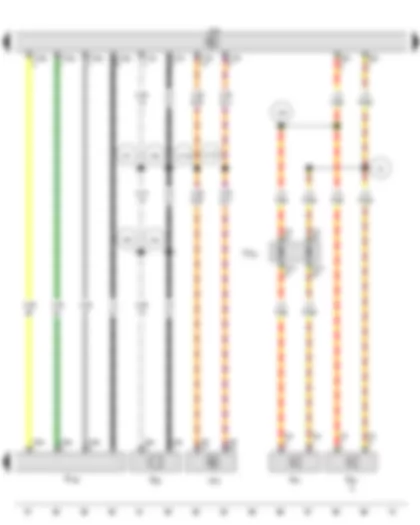
Wiring Diagram VW GOLF 2014 - Heated rear window relay - Control unit 1 for information electronics - Roof aerial - GPS aerial - Radio aerial 2 - Left aerial module - Satellite aerial - Amplitude modulation (AM) frequency filter - Frequency modulation (FM) frequency filter in negative wire - Frequency modulation (FM) frequency filter in positive wire - GSM aerial - Heated rear window
| J9 | Heated rear window relay |
| J794 | Control unit 1 for information electronics |
| RX5 | Roof aerial |
| R50 | GPS aerial |
| R93 | Radio aerial 2 |
| R108 | Left aerial module, Rear window, top left |
| R170 | Satellite aerial |
| R177 | Amplitude modulation (AM) frequency filter |
| R178 | Frequency modulation (FM) frequency filter in negative wire |
| R179 | Frequency modulation (FM) frequency filter in positive wire |
| R205 | GSM aerial |
| T10d | 10-pin connector, black |
| T10p | 10-pin connector, black |
| THK | Coupling point on rear lid |
| Z1 | Heated rear window |
| 285 | Earth connection 7, in interior wiring harness |
| 729 | Earth point, on left rear wheel housing |
| * | Rear window aerial |
| *2 | According to equipment |
VW GOLF 2014 Overview of fuse holder
| q | Fuse assignment, from January 2014 |
| q | Fuse assignment, from January 2014 |
| q | Fuse assignment, from January 2014 |
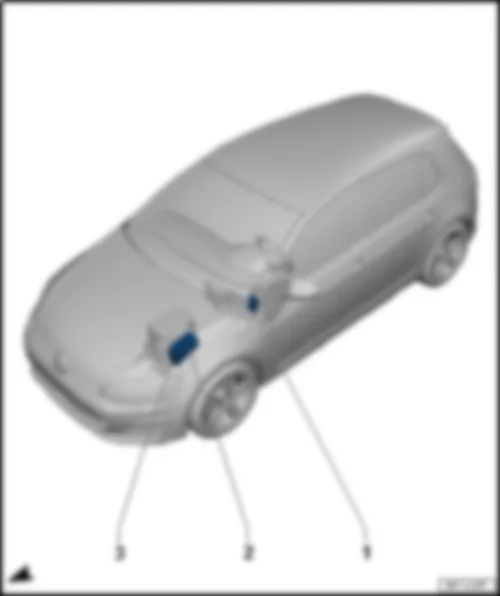
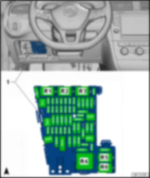
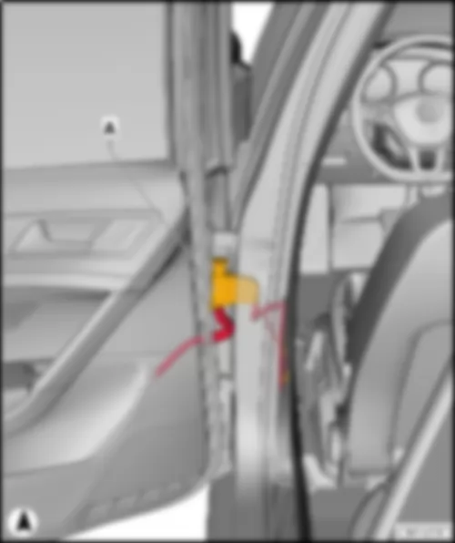
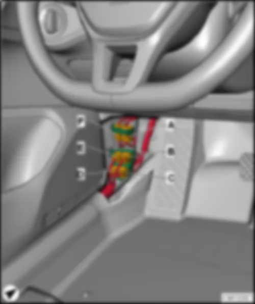
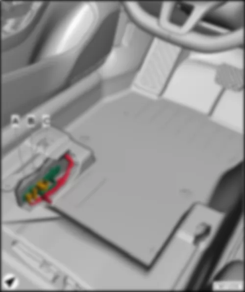
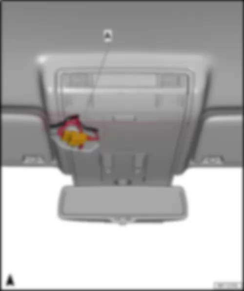
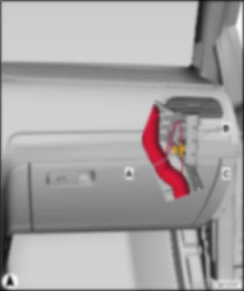
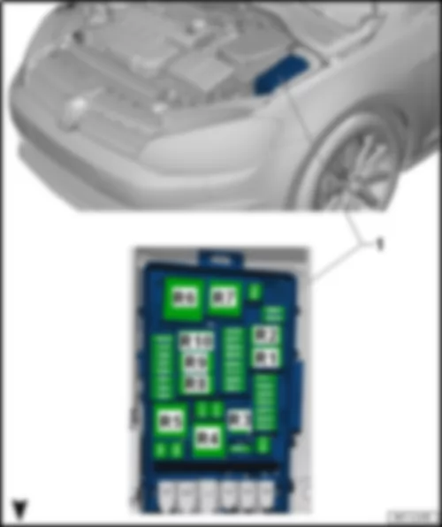
| Fitting location fuse holder C -SC- |
| 1 - | Fuse holder C -SC- |
| Fuse colours for J-Case fuse: |
| t | 50 A - red |
| t | 40 A - green |
| t | 30 A - pink |
| Fuse colours for ATO flat fuse: |
| t | 40 A - orange |
| t | 30 A - light green |
| t | 25 A - natural (white) |
| t | 20 A - yellow |
| t | 15 A - light blue |
| t | 10 A - red |
| t | 7.5 A - brown |
| t | 5 A - light brown |
| t | 1 A - black |
| Fuse colours for mini fuse: |
| t | 20 A - yellow |
| t | 15 A - light blue |
| t | 10 A - red |
| t | 7.5 A - brown |
| t | 5 A - light brown |
| t | 1 A - black |
|
| Fuse assignment fuse holder C -SC- , from January 2014 |
| Slot | Current Flow Diagram designation | Nominal value | Function/component | Terminal | ||
| F1 | Fuse 1 on fuse holder C -SC1- | 30 A | Coupling point in luggage compartment, centre6) | 30 | ||
| F2 | Fuse 2 on fuse holder C -SC2- | 15 A | Steering column electronics control unit -J527-5) | 30 | ||
| F3 | Fuse 3 on fuse holder C -SC3- | - | Special vehicle fuse/depending on equipment | - | ||
| F4 | Fuse 4 on fuse holder C -SC4- | 10 A | Onboard supply control unit -J519-
| 30 | ||
| F5 | Fuse 5 on fuse holder C -SC5- | 5 A | Data bus diagnostic interface -J533- | 30 | ||
| F6 | Not assigned | - | ||||
| F7 | Fuse 7 on fuse holder C -SC7- | 10 A | Heater and air conditioning controls -EX21- | 30 | ||
| Heater control unit -J65- | ||||||
| Climatronic control unit -J255- | ||||||
| Air conditioning system control unit -J301- | ||||||
| Selector lever -E313- | ||||||
| Heated rear window relay -J9- | ||||||
| F8 | Fuse 8 on fuse holder C -SC8- | 10 A | Rotary light switch -EX1- | 30 | ||
| Electromechanical parking brake button -E538- | ||||||
| Air humidity, rain and light sensor -G823- | ||||||
| Diagnostic connection -U31- | ||||||
| F9 | Fuse 9 on fuse holder C -SC9- | 1 A | Steering column electronics control unit -J527- | 30 | ||
| F10 | Fuse 10 on fuse holder C -SC10- | 10 A | Display unit for front information display and operating unit control unit -J685- | 30 | ||
| F11 | Not assigned | - | - | |||
| F12 | Fuse 12 on fuse holder C -SC12- | 20 A | Control unit 1 for information electronics -J794- | 30 | ||
| F13 | Fuse 13 on fuse holder C -SC13- | 15 A | Electronically controlled damping control unit -J250- | 30 | ||
| F14 | Fuse 14 on fuse holder C -SC14- | 30 A | Fresh air blower control unit -J126- | 30 | ||
| F15 | Fuse 15 on fuse holder C -SC15- | 10 A | Control unit for electronic steering column lock -J764- | 30 | ||
| F16 | Fuse 16 on fuse holder C -SC16- | 7.5 A | Storage compartment with interface for mobile telephone -R265- | 30 | ||
| F17 | Fuse 17 on fuse holder C -SC17- | 5 A | Control unit in dash panel insert -J285- | 30 | ||
| Dash panel insert -KX2- | ||||||
| Navigation system interface -R94- | ||||||
| F18 | Fuse 18 on fuse holder C -SC18- | 7.5 A | Reversing camera -R189- | 30 | ||
| Rear lid handle release button -E234- | ||||||
| F19 | Fuse 19 on fuse holder C -SC19- | 7.5 A | Interface for entry and start system -J965- | 30 | ||
| F20 | Fuse 20 on fuse holder C -SC20- | 5 A | Control unit for fuel tank leak detection -J909- | 30 | ||
| Relay for reducing agent metering system -J963-6) | ||||||
| F21 | Not assigned | - | - | |||
| F22 | Not assigned | - | - | |||
| F23 | Fuse 23 on fuse holder C -SC23- | 40 A | Onboard supply control unit -J519-
| 30 | ||
| F24 | Fuse 24 on fuse holder C -SC24- | 30 A | Sliding sunroof adjustment control unit -J245- | 30 | ||
| F25 | Fuse 25 on fuse holder C -SC25- | 30 A | Driver door control unit -J386- | 30 | ||
| Rear left window regulator motor -V26- | 30 | |||||
| F26 | Fuse 26 on fuse holder C -SC26- | 30 A | Onboard supply control unit -J519-
| 30 | ||
| F27 | Fuse 27 on fuse holder C -SC27- | 30 A | Digital sound package control unit -J525- | 30 | ||
| F28 | Fuse 28 on fuse holder C -SC28- | 20 A | Trailer detector control unit -J345- | 30 | ||
| F29 | Fuse 29 on fuse holder C -SC29- | - | Special vehicle fuse/depending on equipment | - | ||
| F30 | Not assigned | - | - | |||
| F31 | Fuse 31 on fuse holder C -SC31- | 40 A | Onboard supply control unit -J519-
| 30 | ||
| F32 | Fuse 32 on fuse holder C -SC32- | 7.5 A | Adaptive cruise control unit -J428- | 15 | ||
| Parking aid control unit -J446- | ||||||
| F33 | Fuse 33 on fuse holder C -SC33- | 5 A | Airbag control unit -J234- | 15 | ||
| Front passenger front airbag deactivated warning lamp -K145- | ||||||
| F34 | Fuse 34 on fuse holder C -SC34- | 7.5 A | Rotary light switch -EX1- | 15 | ||
| Interior mirror -EX5- | ||||||
| Relay for power sockets -J807- | ||||||
| Reversing light switch -F4- | ||||||
| Pressure sender for refrigerant circuit -G805- | ||||||
| Air quality sensor -G238- | ||||||
| Control unit for structure-borne sound -J869-4) | ||||||
| TCS and ESP button -E256- | ||||||
| F35 | Fuse 35 on fuse holder C -SC35- | 10 A | Diagnostic connection -U31- | 15 | ||
| Headlight range control and instrument illumination regulator -EX14- | ||||||
| Control unit for cornering light and headlight range control -J745- | ||||||
| Left headlight range control motor -V48- | ||||||
| Right headlight range control motor -V49- | ||||||
| F36 | Fuse 36 on fuse holder C -SC36- | 10 A | Control unit for right daytime running light and side light -J861- | 15 | ||
| F37 | Fuse 37 on fuse holder C -SC37- | 10 A | Control unit for left daytime running light and side light -J860- | 15 | ||
| F38 | Fuse 38 on fuse holder C -SC38- | 20 A | Trailer detector control unit -J345- | 30 | ||
| F39 | Fuse 39 on fuse holder C -SC39- | 30 A | Front passenger door control unit -J387- | 30 | ||
| Rear right window regulator motor -V27- | ||||||
| F40 2) , 3) | Fuse 40 on fuse holder C -SC40- | 20 A | Cigarette lighter -U1- 1) | 15 2) / 30 3) | ||
| 12 V socket -U5- | ||||||
| 12 V socket 2 -U18- | ||||||
| F41 | Not assigned | - | - | - | ||
| F42 | Fuse 42 on fuse holder C -SC42- | 40 A | Onboard supply control unit -J519-
| 30 | ||
| F43 | Fuse 43 on fuse holder C -SC43- | 30 A | Onboard supply control unit -J519- | 30 | ||
| F44 | Fuse 44 on fuse holder C -SC44- | 15 A | Trailer detector control unit -J345- | 30 | ||
| F45 | Fuse 45 on fuse holder C -SC45- | 15 A | Driver seat lumbar support adjustment switch -E176- | 30 | ||
| Driver seat adjustment operating unit -E470- | ||||||
| F46 | Not assigned | - | - | |||
| F47 | Fuse 47 on fuse holder C -SC47- | 15 A | Rear window wiper motor -V12- | 15 | ||
| F48 | Not assigned | - | - | |||
| F49 | Fuse 49 on fuse holder C -SC49- | 5 A | Clutch position sender -G476- | 15 | ||
| Starter relay 1 -J906- | ||||||
| Starter relay 2 -J907- | ||||||
| F50 | Not assigned | - | - | |||
| F51 | Not assigned | - | - | |||
| F52 | Not assigned | - | - | |||
| F53 | Fuse 53 on fuse holder C -SC53- | 30 A | Heated rear window relay -J9- | 15 |
| 1) Smokers version |
| 2) Factory fitted with power supply from terminal 15 |
| 3) Power supply via terminal 30 possible |
| 4) Only GTI models |
| 5) Only models with heated steering wheel |
| 6) Only models with reducing agent metering system |
Note
| The fuse SC40 is supplied via terminal 15 from the factory and can be supplied via terminal 30 by reconnecting. If a consumer is connected to the electric socket or to the cigarette lighter, ensure that the consumer is disconnected from the voltage supply when the engine is switched off to prevent the drive battery being discharged. |
|
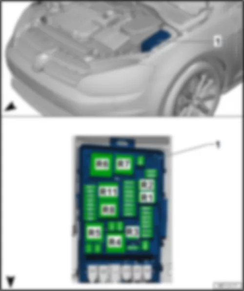
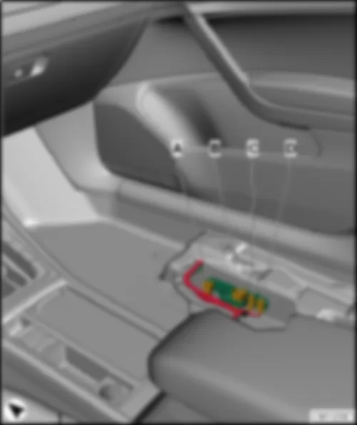
| Fitting location fuse holder B -SB- |
| 1 - | Fuse holder B -SB- |
| Fuse colours for J-Case fuse: |
| t | 50 A - red |
| t | 40 A - green |
| t | 30 A - pink |
| Fuse colours for ATO flat fuse: |
| t | 40 A - orange |
| t | 30 A - light green |
| t | 25 A - natural (white) |
| t | 20 A - yellow |
| t | 15 A - light blue |
| t | 10 A - red |
| t | 7.5 A - brown |
| t | 5 A - light brown |
| t | 1 A - black |
|
| Fuse assignment fuse holder B -SB- , January 2014 |
| Slot | Current Flow Diagram designation | Nominal value | Function/component | Terminal | ||
| F1 | Fuse 1 on fuse holder B -SB1- | 40 A | ABS control unit -J104- | 30 | ||
| F2 | Fuse 2 on fuse holder B -SB2- | 40 A | ABS control unit -J104- | 30 | ||
| ABS hydraulic pump -V64- | ||||||
| F3 | Fuse 3 on fuse holder B -SB3- | 15 A 1) 30 A 2) | Engine control unit -J623- | 87 | ||
| F4 | Fuse 4 on fuse holder B -SB4- | 5 A 2) 10 A 1) | Oil level and oil temperature sender -G266- | 87 | ||
| Radiator fan control unit -J293- | ||||||
| Activated charcoal filter solenoid valve 1 -N80- 1) | ||||||
| Camshaft control valve 1 -N205-1) | ||||||
| Exhaust camshaft control valve 1 -N318- 1) | ||||||
| Valve for oil pressure control -N428- 1) | ||||||
| High heat output relay -J360- 2) | ||||||
| Exhaust gas recirculation cooler changeover valve -N345- 2) | ||||||
| Low heat output relay -J359- 2) | ||||||
| Charge pressure control solenoid valve -N75- 2) | ||||||
| Inlet cam actuator for cylinder 2 -N583- 1) | ||||||
| Exhaust cam actuator for cylinder 2 -N587- 1) | ||||||
| Inlet cam actuator for cylinder 3 -N591- 1) | ||||||
| Exhaust cam actuator for cylinder 3 -N595- 1) | ||||||
| Ethanol concentration sender -G708- 1) | ||||||
| Turbocharger air recirculation valve -N249-4) | ||||||
| Intake manifold flap valve -N316-4) | ||||||
| Piston cooling jet control valve -N522-4) | ||||||
| F5 | Fuse 5 on fuse holder B -SB5- | 10 A 2) | Fuel pressure regulating valve -N276- | 87 | ||
| Fuel metering valve -N290- | ||||||
| Engine component current supply relay -J757-4) | ||||||
| F6 | Fuse 6 on fuse holder B -SB6- | 5 A | Brake light switch -F- | 87 | ||
| F7 | Fuse 7 on fuse holder B -SB7- | 7.5 A 1) 10 A 2) | Fuel pressure regulating valve -N276- 1) | 87 | ||
| Charge air cooling pump -V188- 1) | ||||||
| Valve for oil pressure control -N428-2) | ||||||
| Solenoid for coolant circuit -N492-2) | ||||||
| Charge air cooling pump -V188- 2) | ||||||
| Gearbox oil cooling pump -V478-4) | ||||||
| Coolant shut-off valve -N82-4) | ||||||
| Auxiliary pump for heating -V488- 2) | ||||||
| Radiator blind control motor -V544-2) | ||||||
| F8 | Fuse 8 on fuse holder B -SB8- | 10 A 1) 15 A 2) | Lambda probe heater -Z19- | 87 | ||
| Lambda probe 1 before catalytic converter -GX10- | ||||||
| Lambda probe 1 heater after catalytic converter -Z29- | ||||||
| Lambda probe 1 after catalytic converter -GX7- | ||||||
| F9 | Fuse 9 on fuse holder B -SB9- | 5 A 2) 20 A 1) | Ignition coil 1 with output stage -N70- 1) | 87 | ||
| Ignition coil 2 with output stage -N127-1) | ||||||
| Ignition coil 3 with output stage -N291- 1) | ||||||
| Ignition coil 4 with output stage -N292-1) | ||||||
| Automatic glow period control unit -J179- 2) | ||||||
| Air mass meter -G70- | ||||||
| Intake manifold preheating heater element -N51- 2) | ||||||
| 10A 1) | Exhaust flap control unit -J883- 1) | |||||
| Sender 1 for secondary air pressure -G609- 1) | ||||||
| Charge air cooling pump -V188- 1) | ||||||
| Activated charcoal filter solenoid valve 1 -N80- 1) | ||||||
| Camshaft control valve 1 -N205- 1) | ||||||
| Exhaust camshaft control valve 1 -N318- 1) | ||||||
| F10 | Fuse 10 on fuse holder B -SB10- | 10 A 1) 20 A 2) | Fuel pump control unit -J538- | 87 | ||
| F11 | Fuse 11 on fuse holder B -SB11- | 40 A | Auxiliary air heater element -Z35- | 87 | ||
| F12 | Fuse 12 on fuse holder B -SB12- | 40 A | Auxiliary air heater element -Z35- | 87 | ||
| F13 | Fuse 13 on fuse holder B -SB13- | 30 A | Automatic gearbox control unit -J217- | 30 | ||
| Mechatronic unit for dual clutch gearbox -J743- | ||||||
| ||||||
| 15 A | Mechatronic unit for dual clutch gearbox -J743- | |||||
| ||||||
| F14 | Not assigned | - | ||||
| F15 | Fuse 15 on fuse holder B -SB15- | 15 A | Horn relay -J413- | 30 | ||
| F16 | Fuse 16 on fuse holder B -SB16- | 20 A | Engine component current supply relay -J757-4) | 30 | ||
| F17 | Fuse 17 on fuse holder B -SB17- | 7.5 A | Main relay -J271- 1) | 30 | ||
| Terminal 30 voltage supply relay -J317- 2) | ||||||
| Engine control unit -J623- | ||||||
| ABS control unit -J104- | ||||||
| Heated windscreen relay -J47- | ||||||
| F18 | Fuse 18 on fuse holder B -SB18- | 5 A | Battery monitoring control unit -J367- | 30 | ||
| Data bus diagnostic interface -J533- 3) | ||||||
| F19 | Fuse 19 on fuse holder B -SB19- | 30 A | Wiper motor control unit -J400- | 30 | ||
| F20 | Not assigned | - | - | |||
| F21 | Not assigned | - | - | |||
| F22 | Fuse 22 on fuse holder B -SB22- | 5 A | Engine control unit -J623- | 50 | ||
| F23 | Fuse 23 on fuse holder B -SB23- | 30 A | Starter -B- | 50 | ||
| F24 | Fuse 24 on fuse holder B -SB24- | 40 A | Auxiliary air heater element -Z35- | 87 | ||
| F25 | Not assigned | - | - | |||
| F26 | Not assigned | - | - | |||
| F27 | Not assigned | - | - | |||
| F28 | Not assigned | - | - | |||
| F29 | Not assigned | - | - | |||
| F30 | Not assigned | - | - | |||
| F31 | Not assigned | - | - | |||
| F32 | Not assigned | - | - | |||
| F33 | Not assigned | - | - | |||
| F34 | Fuse 34 on fuse holder B -SB34- | 15 A | Axle differential lock control unit -J647-4) | 30 | ||
| F35 | Not assigned | - | - | |||
| F36 | Not assigned | - | - | |||
| F37 | Not assigned | - | - | |||
| F38 | Not assigned | - | - |
| 1) Only models with petrol engine |
| 2) Only models with diesel engine |
| 3) Only models with no start/stop system |
| 4) Only GTI models |
|
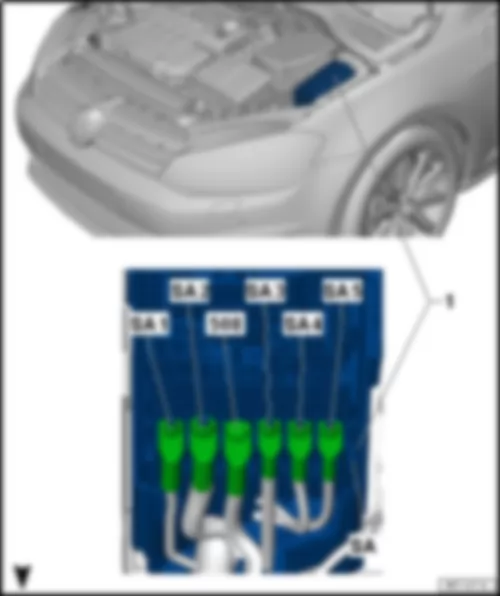
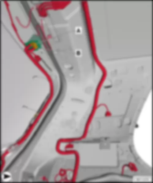
| Fitting location fuse holder A -SA- |
| 1 - | Fuse holder A -SA- |
| 508 - | Threaded connection (30) on E-box |
Note
|
| Fuse assignment fuse holder A -SA- , January 2014 |
| Screw location | Current Flow Diagram designation | Nominal value | Function/component | Terminal |
| J1 | Fuse 1 on fuse holder A -SA1- | 125 A | Supply for fuses: | 30 |
| -SC4- …-SC14- | ||||
| -SC30- | ||||
| -SC31- | ||||
| -SC38- | ||||
| -SC39- | ||||
| -SC41- | ||||
| -SC42- | ||||
| -SC53- | ||||
| Terminal 15 voltage supply relay -J329- | ||||
| G1 | Fuse 2 on fuse holder A -SA2- | 400 A | Alternator -C- | 30 |
| E1 | Fuse 3 on fuse holder A -SA3- | 80 A | Power steering control unit -J500- | 30 |
| K1 | Fuse 4 on fuse holder A -SA4- | 80 A | Supply for fuses: | 30 |
| -SC15- …-SC20- | ||||
| -SC23- …-SC28- | ||||
| -SB43- …-SB45- | ||||
| L1 | Fuse 5 on fuse holder A -SA5- | 50 A | Radiator fan -VX57- | 30 |
| Back to overview |

