AUTOMOTIVE ELECTRICIANS PORTAL

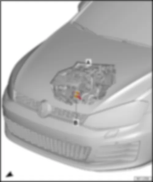
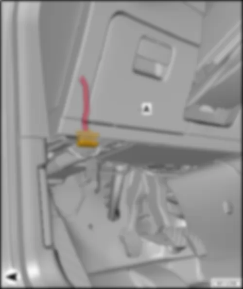
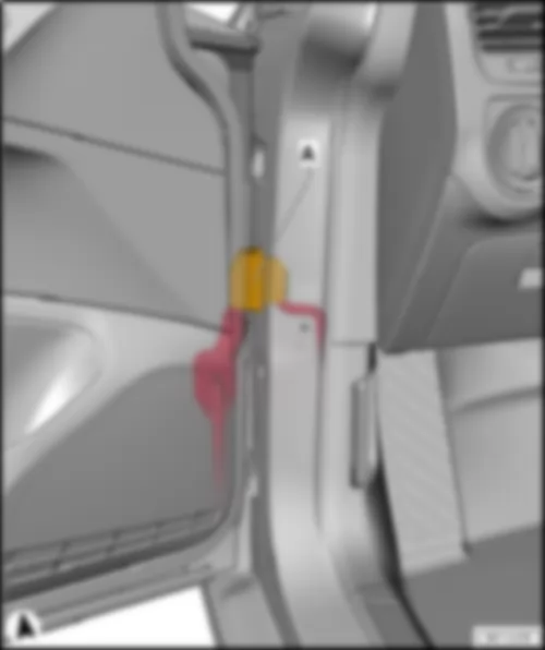
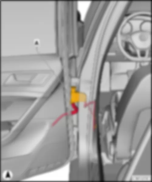
VW GOLF 2014 – 2.0l diesel engine, DEJA . Wiring diagrams, Pin Connector, Location

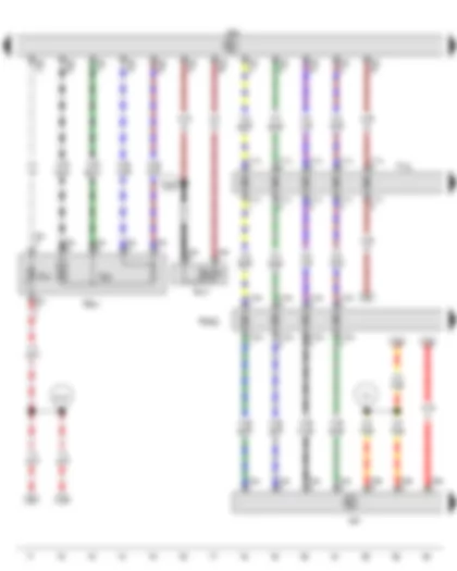
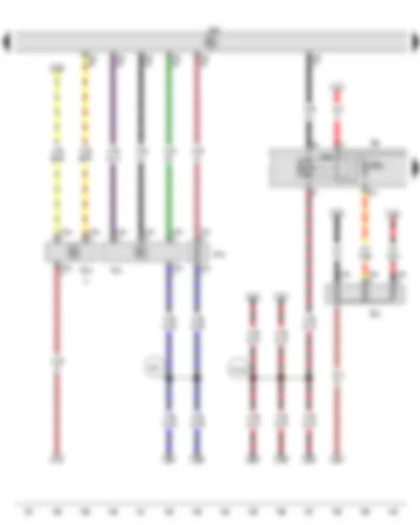
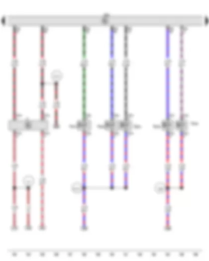
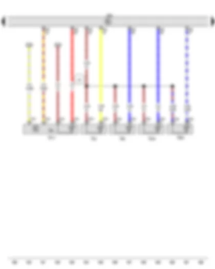
Wiring Diagram VW GOLF 2014 - Starter - Battery monitor control unit - Starter relay 1 - Starter relay 2 - Fuse holder B


Wiring Diagram  VW GOLF 2014 - Starter - Battery monitor control unit - Starter relay 1 - Starter relay 2 - Fuse holder B https://portal-diagnostov.com/license.html
https://portal-diagnostov.com/license.html Automotive Electricians Portal FZCO Automotive Electricians Portal FZCO
Download PDF file
A Battery
B Starter
J367 Battery monitor control unit
J906 Starter relay 1
J907 Starter relay 2
SB Fuse holder B, in E-box in engine compartment
SB17 Fuse 17 on fuse holder B
SB18 Fuse 18 on fuse holder B
SB22 Fuse 22 on fuse holder B
SB23 Fuse 23 on fuse holder B
T2bn 2-pin connector, yellow
  508 Threaded connection (30) on E-box
  B698 Connection 3 (LIN bus) in main wiring harness
  D52 Positive connection (15a), in engine compartment wiring harness
*Cross-section 35.0 possible
*2Earth supply via housing
*3Only models with no start/stop system

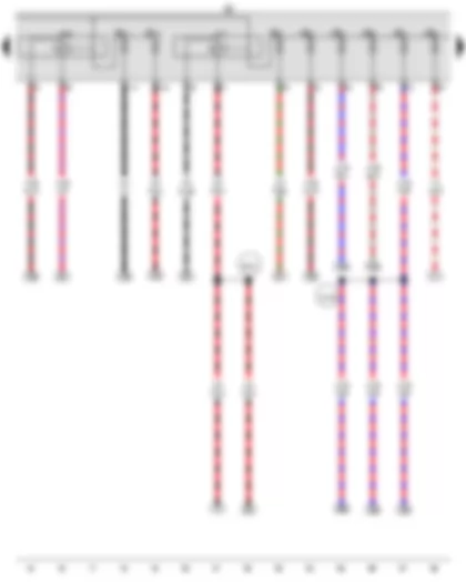
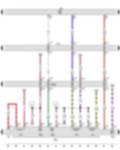
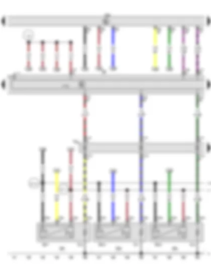
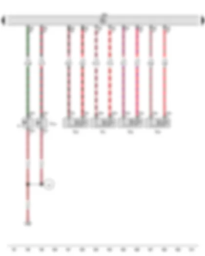
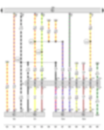
Wiring Diagram VW GOLF 2014 - Terminal 30 voltage supply relay - High heat output relay - Fuse holder B


Wiring Diagram  VW GOLF 2014 - Terminal 30 voltage supply relay - High heat output relay - Fuse holder B https://portal-diagnostov.com/license.html
https://portal-diagnostov.com/license.html Automotive Electricians Portal FZCO Automotive Electricians Portal FZCO
Get access to all wiring diagrams of the carDownload PDF file
J317 Terminal 30 voltage supply relay
J360 High heat output relay
SB Fuse holder B, in E-box in engine compartment
SB3 Fuse 3 on fuse holder B
SB4 Fuse 4 on fuse holder B
SB5 Fuse 5 on fuse holder B
SB6 Fuse 6 on fuse holder B
SB7 Fuse 7 on fuse holder B
SB8 Fuse 8 on fuse holder B
SB11 Fuse 11 on fuse holder B
SB12 Fuse 12 on fuse holder B
  B315 Positive connection 1 (30a) in main wiring harness
  D183 Connection 4 (87a) in engine compartment wiring harness

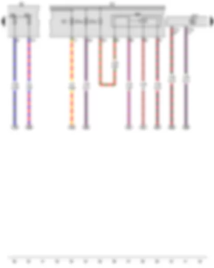
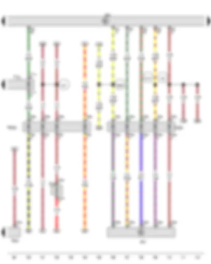
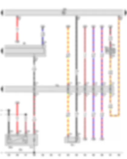
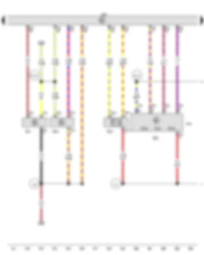
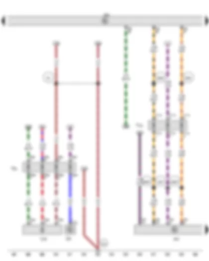
Wiring Diagram VW GOLF 2014 - Onboard supply control unit - Relay for reducing agent metering system - Fuse holder B - Fuse holder C


Wiring Diagram  VW GOLF 2014 - Onboard supply control unit - Relay for reducing agent metering system - Fuse holder B - Fuse holder C https://portal-diagnostov.com/license.html
https://portal-diagnostov.com/license.html Automotive Electricians Portal FZCO Automotive Electricians Portal FZCO
Get access to all wiring diagrams of the carDownload PDF file
J519 Onboard supply control unit
J963 Relay for reducing agent metering system
SB Fuse holder B, in E-box in engine compartment
SC Fuse holder C, in interior, in front left in footwell
SC1 Fuse 1 on fuse holder C
SB9 Fuse 9 on fuse holder B
SB10 Fuse 10 on fuse holder B
SC20 Fuse 20 on fuse holder C
SC49 Fuse 49 on fuse holder C
T73a 73-pin connector, black
T73c 73-pin connector, black

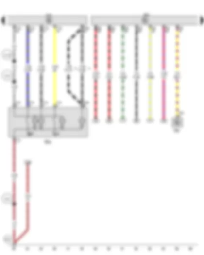
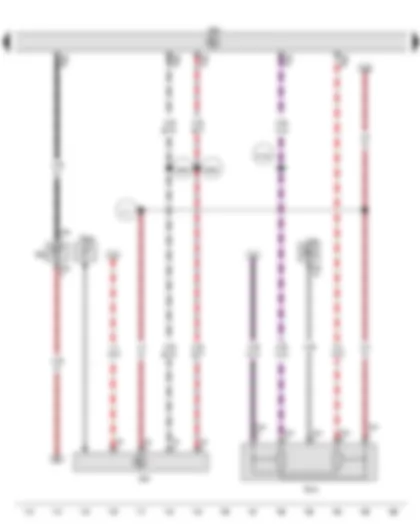
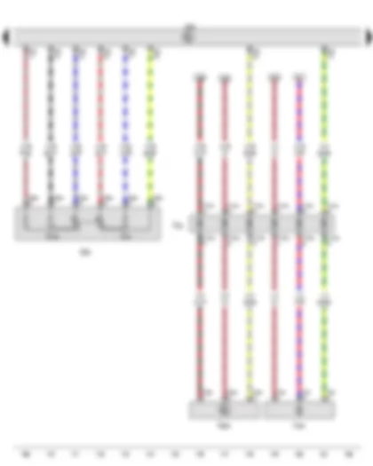
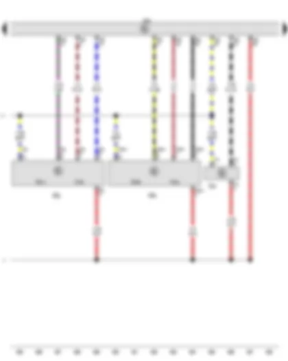
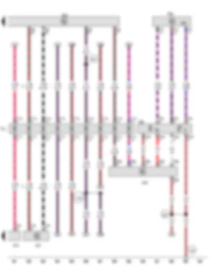
Wiring Diagram VW GOLF 2014 - Switch module 1 in centre console - Onboard supply control unit - Engine control unit - Radiator fan


Wiring Diagram  VW GOLF 2014 - Switch module 1 in centre console - Onboard supply control unit - Engine control unit - Radiator fan https://portal-diagnostov.com/license.html
https://portal-diagnostov.com/license.html Automotive Electricians Portal FZCO Automotive Electricians Portal FZCO
Get access to all wiring diagrams of the carDownload PDF file
EX23 Switch module 1 in centre console
E693 Start/Stop operation button
E735 Driving mode selection button
J519 Onboard supply control unit
J623 Engine control unit
T4cx 4-pin connector, black
T10j 10-pin connector, black
T73c 73-pin connector, black
T94 94-pin connector, black
VX57 Radiator fan
  278 Earth connection 4, in interior wiring harness
  810 Earth point on central tube for dash panel, centre left
  A19 Connection (58d), in dash panel wiring harness
  A116 Connection 2 (58d), in dash panel wiring harness
*Pre-wired component
*2Only models with start/stop system
*3According to equipment
*4Up to June 2015
*5From June 2015

Wiring Diagram VW GOLF 2014 - Exhaust gas temperature sender 3 - Exhaust gas temperature sender 4 - Engine control unit


Wiring Diagram  VW GOLF 2014 - Exhaust gas temperature sender 3 - Exhaust gas temperature sender 4 - Engine control unit https://portal-diagnostov.com/license.html
https://portal-diagnostov.com/license.html Automotive Electricians Portal FZCO Automotive Electricians Portal FZCO
Get access to all wiring diagrams of the carDownload PDF file
G448 Exhaust gas temperature sender 2
G495 Exhaust gas temperature sender 3
G648 Exhaust gas temperature sender 4
J623 Engine control unit
T2as 2-pin connector, brown
T2at 2-pin connector, orange
T2br 2-pin connector, black
T94 94-pin connector, black
  201 Earth connection 5, in engine compartment wiring harness
  671 Earth point 1, on front of left longitudinal member
  B438 Connection 2 (GND (earth)), in main wiring harness
  D202 Connection 6 (87a) in engine compartment wiring harness

Wiring Diagram VW GOLF 2014 - Lambda probe 1 before catalytic converter - Engine control unit - Control unit for reducing-agent heater - Injector for reducing agent


Wiring Diagram  VW GOLF 2014 - Lambda probe 1 before catalytic converter - Engine control unit - Control unit for reducing-agent heater - Injector for reducing agent https://portal-diagnostov.com/license.html
https://portal-diagnostov.com/license.html Automotive Electricians Portal FZCO Automotive Electricians Portal FZCO
Get access to all wiring diagrams of the carDownload PDF file
GX10 Lambda probe 1 before catalytic converter
G39 Lambda probe
J623 Engine control unit
J891 Control unit for reducing-agent heater
N474 Injector for reducing agent
T2fb 2-pin connector, black
T4aj 4-pin connector, black
T5ca 5-pin connector, colourless
T6w 6-pin connector, black
T10kt 10-pin connector, black
T10ku 10-pin connector, black
T17h 17-pin connector, green
T17q 17-pin connector, green, green
T94 94-pin connector, black
TIUL Coupling point in interior, below left
TRMD Coupling point for reducing agent metering system
Z19 Lambda probe heater
  D86 Connection (hydraulic pump warning lamp), in engine compartment wiring harness
  D197 Connection 5 (87a) in engine compartment wiring harness
  H3 Connection 1 in wiring harness for reducing-agent tank
*Pre-wired component

Wiring Diagram VW GOLF 2014 - Delivery unit for reducing agent metering system - Temperature sender for reducing agent - Reducing agent level sender - Reducing agent quality sensor - Engine control unit - Control unit for reducing-agent heater - Pump for reducing agent - Reducing agent return flow pump - Heater for reducing-agent tank (heater circuit 1)


Wiring Diagram  VW GOLF 2014 - Delivery unit for reducing agent metering system - Temperature sender for reducing agent - Reducing agent level sender - Reducing agent quality sensor - Engine control unit - Control unit for reducing-agent heater - Pump for reducing agent - Reducing agent return flow pump - Heater for reducing-agent tank (heater circuit 1) https://portal-diagnostov.com/license.html
https://portal-diagnostov.com/license.html Automotive Electricians Portal FZCO Automotive Electricians Portal FZCO
Get access to all wiring diagrams of the carDownload PDF file
GX19 Delivery unit for reducing agent metering system
G685 Temperature sender for reducing agent
G697 Reducing agent level sender
G849 Reducing agent quality sensor
J623 Engine control unit
J891 Control unit for reducing-agent heater
T3dq 3-pin connector, black
T4cy 4-pin connector, black
T5bc 5-pin connector, black
T5ca 5-pin connector, colourless
T10kt 10-pin connector, black
T10ku 10-pin connector, black
T17h 17-pin connector, green
T17q 17-pin connector, green, green
T94 94-pin connector, black
TIUL Coupling point in interior, below left
TRMD Coupling point for reducing agent metering system
V437 Pump for reducing agent
V561 Reducing agent return flow pump
Z102 Heater for reducing-agent tank (heater circuit 1)
  H4 Connection 2 in wiring harness for reducing-agent tank
  H5 Connection 3 in wiring harness for reducing-agent tank

Wiring Diagram VW GOLF 2014 - Reducing agent quality sensor - Engine control unit - Exhaust flap control unit - Heater for reducing-agent line (heater circuit 2)


Wiring Diagram  VW GOLF 2014 - Reducing agent quality sensor - Engine control unit - Exhaust flap control unit - Heater for reducing-agent line (heater circuit 2) https://portal-diagnostov.com/license.html
https://portal-diagnostov.com/license.html Automotive Electricians Portal FZCO Automotive Electricians Portal FZCO
Get access to all wiring diagrams of the carDownload PDF file
G849 Reducing agent quality sensor
J623 Engine control unit
J883 Exhaust flap control unit
T2dd 2-pin connector, black
T3dq 3-pin connector, black
T5aa 5-pin connector, black
T5ab 5-pin connector, brown
T5ao 5-pin connector, brown
T6ce 6-pin connector, black
T6cf 6-pin connector, black
T17h 17-pin connector, green
T17q 17-pin connector, green, green
T94 94-pin connector, black
TAGK Coupling point for exhaust flap control unit
TIUL Coupling point in interior, below left
TRMD Coupling point for reducing agent metering system
Z104 Heater for reducing-agent line (heater circuit 2)
  327 Earth connection (sender earth), in engine compartment wiring harness
  481 Earth connection 2, in fuel tank wiring harness
  B369 Connection 1 (5V), in main wiring harness
  D107 Connection 5 in engine compartment wiring harness

Wiring Diagram VW GOLF 2014 - Radiator outlet coolant temperature sender - NOx sender - Clutch position sender - ABS control unit - Control unit for NOx sender - Engine control unit


Wiring Diagram  VW GOLF 2014 - Radiator outlet coolant temperature sender - NOx sender - Clutch position sender - ABS control unit - Control unit for NOx sender - Engine control unit https://portal-diagnostov.com/license.html
https://portal-diagnostov.com/license.html Automotive Electricians Portal FZCO Automotive Electricians Portal FZCO
Get access to all wiring diagrams of the carDownload PDF file
G83 Radiator outlet coolant temperature sender
G295 NOx sender
G476 Clutch position sender
J104 ABS control unit
J583 Control unit for NOx sender
J623 Engine control unit
T2cx 2-pin connector, black
T5f 5-pin connector, black
T5m 5-pin connector, black
T46 46-pin connector, black
T94 94-pin connector, black
  317 Earth connection 7, in engine compartment wiring harness
  B385 Connection 3 (powertrain CAN bus, high), in main wiring harness
  B392 Connection 3 (powertrain CAN bus, low), in main wiring harness
  D102 Connection 2 in engine compartment wiring harness
*Adapter wire

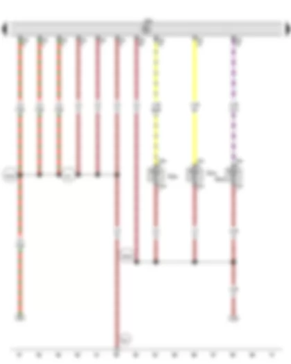
Wiring Diagram VW GOLF 2014 - Air mass meter - Gearbox neutral position sender - Low heat output relay - Engine control unit - Heater element for crankcase breather - Auxiliary air heater element


Wiring Diagram  VW GOLF 2014 - Air mass meter - Gearbox neutral position sender - Low heat output relay - Engine control unit - Heater element for crankcase breather - Auxiliary air heater element https://portal-diagnostov.com/license.html
https://portal-diagnostov.com/license.html Automotive Electricians Portal FZCO Automotive Electricians Portal FZCO
Get access to all wiring diagrams of the carDownload PDF file
G70 Air mass meter
G701 Gearbox neutral position sender
J359 Low heat output relay
J623 Engine control unit
N79 Heater element for crankcase breather
SB Fuse holder B, in E-box
SB24 Fuse 24 on fuse holder B
T2df 2-pin connector, black
T3ar 3-pin connector, black
T3bo 3-pin connector, brown
T4ch 4-pin connector, black
T94 94-pin connector, black
Z35 Auxiliary air heater element
  D182 Connection 3 (87a) in engine compartment wiring harness
  E78 Connection 2 (87a) in engine wiring harness
*Only models with start/stop system
*2Only models with manual gearbox

Wiring Diagram VW GOLF 2014 - Automatic glow period control unit - Engine control unit


Wiring Diagram  VW GOLF 2014 - Automatic glow period control unit - Engine control unit https://portal-diagnostov.com/license.html
https://portal-diagnostov.com/license.html Automotive Electricians Portal FZCO Automotive Electricians Portal FZCO
Get access to all wiring diagrams of the carDownload PDF file
G677 Cylinder 1 combustion chamber pressure sender
G678 Cylinder 2 combustion chamber pressure sender
G679 Cylinder 3 combustion chamber pressure sender
J179 Automatic glow period control unit
J623 Engine control unit
QX1 Glow plug 1
QX2 Glow plug 2
QX3 Glow plug 3
Q10 Glow plug 1
Q11 Glow plug 2
Q12 Glow plug 3
SB Fuse holder B, in E-box
T4eu 4-pin connector
T4ev 4-pin connector, black
T4ew 4-pin connector, black
T14h 14-pin connector, grey
T14i 14-pin connector, grey
T60 60-pin connector, black
T94 94-pin connector, black
TML Coupling point in engine compartment, left
  179 Earth connection, in left headlight wiring harness
  D110 Connection 8 in engine compartment wiring harness
  D111 Connection 9 in engine compartment wiring harness
*Earth supply via housing

Wiring Diagram VW GOLF 2014 - Charge air temperature sender after charge air cooler - Engine control unit - Charge pressure control solenoid valve


Wiring Diagram  VW GOLF 2014 - Charge air temperature sender after charge air cooler - Engine control unit - Charge pressure control solenoid valve https://portal-diagnostov.com/license.html
https://portal-diagnostov.com/license.html Automotive Electricians Portal FZCO Automotive Electricians Portal FZCO
Get access to all wiring diagrams of the carDownload PDF file
G680 Cylinder 4 combustion chamber pressure sender
G811 Charge air temperature sender after charge air cooler
J623 Engine control unit
N75 Charge pressure control solenoid valve
QX4 Glow plug 4
Q13 Glow plug 4
SB Fuse holder B, in E-box
T2dg 2-pin connector, black
T2di 2-pin connector, black
T4ex 4-pin connector, black
T14h 14-pin connector, grey
T14i 14-pin connector, grey
T60 60-pin connector, black
T94 94-pin connector, black
TML Coupling point in engine compartment, left
  D110 Connection 8 in engine compartment wiring harness
  D111 Connection 9 in engine compartment wiring harness
*Earth supply via housing

Wiring Diagram VW GOLF 2014 - Accelerator pedal module - Oil level and oil temperature sender - Engine control unit - Auxiliary pump for heating


Wiring Diagram  VW GOLF 2014 - Accelerator pedal module - Oil level and oil temperature sender - Engine control unit - Auxiliary pump for heating https://portal-diagnostov.com/license.html
https://portal-diagnostov.com/license.html Automotive Electricians Portal FZCO Automotive Electricians Portal FZCO
Get access to all wiring diagrams of the carDownload PDF file
GX2 Accelerator pedal module
G79 Accelerator position sender
G185 Accelerator position sender 2
G266 Oil level and oil temperature sender
J623 Engine control unit
T3cd 3-pin connector, black
T3ci 3-pin connector, black
T6cd 6-pin connector, black
T10kv 10-pin connector, black
T10kw 10-pin connector, black
T94 94-pin connector, black
TML Coupling point in engine compartment, left
V488 Auxiliary pump for heating

Wiring Diagram VW GOLF 2014 - Brake light switch - Engine control unit - Fuel pressure regulating valve - Fuel metering valve - Valve for oil pressure control - Coolant valve for cylinder head


Wiring Diagram  VW GOLF 2014 - Brake light switch - Engine control unit - Fuel pressure regulating valve - Fuel metering valve - Valve for oil pressure control - Coolant valve for cylinder head https://portal-diagnostov.com/license.html
https://portal-diagnostov.com/license.html Automotive Electricians Portal FZCO Automotive Electricians Portal FZCO
Get access to all wiring diagrams of the carDownload PDF file
F Brake light switch
J623 Engine control unit
N205 Camshaft control valve 1
N276 Fuel pressure regulating valve
N290 Fuel metering valve
N428 Valve for oil pressure control
N489 Coolant valve for cylinder head
T2cp 2-pin connector, black
T2cq 2-pin connector, black
T2cy 2-pin connector, black
T2db 2-pin connector, yellow
T2dj 2-pin connector, brown
T4bc 4-pin connector, black
T60 60-pin connector, black
T94 94-pin connector, black
  131 Earth connection 2, in engine compartment wiring harness
  209 Earth connection 6, in engine compartment wiring harness
  D73 Positive connection (54), in engine compartment wiring harness
  D101 Connection 1 in engine compartment wiring harness
*Up to June 2015

Wiring Diagram VW GOLF 2014 - Oil pressure switch - Oil pressure switch for reduced oil pressure - Engine control unit - Injector - cylinder 1 - Injector - cylinder 2 - Injector - cylinder 3 - Injector - cylinder 4


Wiring Diagram  VW GOLF 2014 - Oil pressure switch - Oil pressure switch for reduced oil pressure - Engine control unit - Injector - cylinder 1 - Injector - cylinder 2 - Injector - cylinder 3 - Injector - cylinder 4 https://portal-diagnostov.com/license.html
https://portal-diagnostov.com/license.html Automotive Electricians Portal FZCO Automotive Electricians Portal FZCO
Get access to all wiring diagrams of the carDownload PDF file
F1 Oil pressure switch
F378 Oil pressure switch for reduced oil pressure
J623 Engine control unit
N30 Injector, cylinder 1
N31 Injector, cylinder 2
N32 Injector, cylinder 3
N33 Injector, cylinder 4
T2cl 2-pin connector, black
T2cm 2-pin connector, black
T2cn 2-pin connector, black
T2co 2-pin connector, black
T2dk 2-pin connector, red
T2dl 2-pin connector, black
T60 60-pin connector, black
  167 Earth connection 4, in engine compartment wiring harness

Wiring Diagram VW GOLF 2014 - Throttle valve module - Hall sender - Fuel pressure sender - Position sender for charge pressure positioner - Engine control unit


Wiring Diagram  VW GOLF 2014 - Throttle valve module - Hall sender - Fuel pressure sender - Position sender for charge pressure positioner - Engine control unit https://portal-diagnostov.com/license.html
https://portal-diagnostov.com/license.html Automotive Electricians Portal FZCO Automotive Electricians Portal FZCO
Get access to all wiring diagrams of the carDownload PDF file
GX3 Throttle valve module
G40 Hall sender
G186 Throttle valve drive for electric throttle
G187 Throttle valve drive angle sender 1 for electric throttle
G188 Throttle valve drive angle sender 2 for electric throttle
G247 Fuel pressure sender
G581 Position sender for charge pressure positioner
J338 Throttle valve module
J623 Engine control unit
T3b 3-pin connector, black
T3bv 3-pin connector, brown
T3bw 3-pin connector, black
T5q 5-pin connector, black
T60 60-pin connector, black
  131 Earth connection 2, in engine compartment wiring harness
  132 Earth connection 3, in engine compartment wiring harness
  D141 Connection (5V) in engine prewiring harness
  D174 Connection 2 (5V) in engine prewiring harness

Wiring Diagram VW GOLF 2014 - Exhaust gas recirculation valve 1 - Exhaust gas recirculation valve 2 - Engine speed sender - Engine control unit


Wiring Diagram  VW GOLF 2014 - Exhaust gas recirculation valve 1 - Exhaust gas recirculation valve 2 - Engine speed sender - Engine control unit https://portal-diagnostov.com/license.html
https://portal-diagnostov.com/license.html Automotive Electricians Portal FZCO Automotive Electricians Portal FZCO
Get access to all wiring diagrams of the carDownload PDF file
GX5 Exhaust gas recirculation valve 1
GX6 Exhaust gas recirculation valve 2
G28 Engine speed sender
G212 Exhaust gas recirculation potentiometer
G466 Exhaust gas recirculation potentiometer 2
J623 Engine control unit
T3v 3-pin connector, black
T5am 5-pin connector, black
T6y 6-pin connector, grey
T60 60-pin connector, black
V338 Exhaust gas recirculation control motor
V339 Exhaust gas recirculation control motor 2
  131 Earth connection 2, in engine compartment wiring harness
  D141 Connection (5V) in engine prewiring harness
*According to equipment

Wiring Diagram VW GOLF 2014 - Intake air temperature sender - Coolant temperature sender - Fuel temperature sender - Exhaust gas temperature sender 1 - Fuel pressure sender for low-pressure - Temperature sensor 2 for exhaust recirculation - Engine control unit


Wiring Diagram  VW GOLF 2014 - Intake air temperature sender - Coolant temperature sender - Fuel temperature sender - Exhaust gas temperature sender 1 - Fuel pressure sender for low-pressure - Temperature sensor 2 for exhaust recirculation - Engine control unit https://portal-diagnostov.com/license.html
https://portal-diagnostov.com/license.html Automotive Electricians Portal FZCO Automotive Electricians Portal FZCO
Get access to all wiring diagrams of the carDownload PDF file
G42 Intake air temperature sender
G62 Coolant temperature sender
G81 Fuel temperature sender
G235 Exhaust gas temperature sender 1
G410 Fuel pressure sender for low-pressure
G690 Temperature sensor 2 for exhaust recirculation
J623 Engine control unit
T2ar 2-pin connector, black
T2cr 2-pin connector, black
T2dn 2-pin connector, black
T2jc 2-pin connector, brown
T4fd 4-pin connector, black
T60 60-pin connector, black
  85 Earth connection 1, in engine compartment wiring harness

Wiring Diagram VW GOLF 2014 - Charge pressure sender - Water separator sender - Exhaust gas pressure sensor 1 - Pressure differential sender - Engine control unit


Wiring Diagram  VW GOLF 2014 - Charge pressure sender - Water separator sender - Exhaust gas pressure sensor 1 - Pressure differential sender - Engine control unit https://portal-diagnostov.com/license.html
https://portal-diagnostov.com/license.html Automotive Electricians Portal FZCO Automotive Electricians Portal FZCO
Get access to all wiring diagrams of the carDownload PDF file
G31 Charge pressure sender
G63 Water separator sender
G450 Exhaust gas pressure sensor 1
G505 Pressure differential sender
J623 Engine control unit
T3bn 3-pin connector, black
T3bs 3-pin connector, black
T3ch 3-pin connector, black
T3r 3-pin connector
T10kx 10-pin connector, black
T10ky 10-pin connector, black
T94 94-pin connector, black
TML Coupling point in engine compartment, left
  B437 Connection 1 (GND (earth)), in main wiring harness
  D103 Connection 3 in engine compartment wiring harness
  D106 Connection 4 in engine compartment wiring harness
  D195 Connection 1 (5V) in engine compartment wiring harness

Wiring Diagram VW GOLF 2014 - Alternator with voltage regulator - Data bus diagnostic interface - Engine control unit - Charge air cooling pump


Wiring Diagram  VW GOLF 2014 - Alternator with voltage regulator - Data bus diagnostic interface - Engine control unit - Charge air cooling pump https://portal-diagnostov.com/license.html
https://portal-diagnostov.com/license.html Automotive Electricians Portal FZCO Automotive Electricians Portal FZCO
Get access to all wiring diagrams of the carDownload PDF file
CX1 Alternator with voltage regulator
J533 Data bus diagnostic interface
J623 Engine control unit
T3cq 3-pin connector, black
T8as 8-pin connector, black
T8at 8-pin connector, black
T17e 17-pin connector, brown
T17m 17-pin connector, brown
T20 20-pin connector, red
T60 60-pin connector, black
T94 94-pin connector, black
TIUL Coupling point in interior, below left
TML Coupling point in engine compartment, left
V188 Charge air cooling pump
  85 Earth connection 1, in engine compartment wiring harness
  673 Earth point 3, on front of left longitudinal member
  A227 Connection 2 (LIN bus) in dash panel wiring harness
  B383 Connection 1 (powertrain CAN bus, high), in main wiring harness
  B384 Connection 2 (powertrain CAN bus, high), in main wiring harness
  B390 Connection 1 (powertrain CAN bus, low), in main wiring harness
  B391 Connection 2 (powertrain CAN bus, low), in main wiring harness
*According to equipment

Wiring Diagram VW GOLF 2014 - Fuel delivery unit - Control unit in dash panel insert - Steering column electronics control unit - Data bus diagnostic interface - Fuel pump control unit - Engine control unit - Dash panel insert


Wiring Diagram  VW GOLF 2014 - Fuel delivery unit - Control unit in dash panel insert - Steering column electronics control unit - Data bus diagnostic interface - Fuel pump control unit - Engine control unit - Dash panel insert https://portal-diagnostov.com/license.html
https://portal-diagnostov.com/license.html Automotive Electricians Portal FZCO Automotive Electricians Portal FZCO
Get access to all wiring diagrams of the carDownload PDF file
G Fuel gauge sender
GX1 Fuel delivery unit
G6 Fuel system pressurisation pump
J285 Control unit in dash panel insert
J527 Steering column electronics control unit
J533 Data bus diagnostic interface
J538 Fuel pump control unit
J623 Engine control unit
KX2 Dash panel insert
T3cj 3-pin connector, black
T4db 4-pin connector, brown
T6cg 6-pin connector, brown
T16r 16-pin connector, black
T17g 17-pin connector, blue
T17o 17-pin connector, blue
T18 18-pin connector, black
T20 20-pin connector, red
T94 94-pin connector, black
TIUL Coupling point in interior, below left
  480 Earth connection, in fuel tank wiring harness
  730 Earth point 1, on right rear wheel housing
  A192 Positive connection 3 (15a) in dash panel wiring harness
  D51 Positive connection 1 (15), in engine compartment wiring harness
*Only models with cruise control system (CCS)
*2Only models with no start/stop system


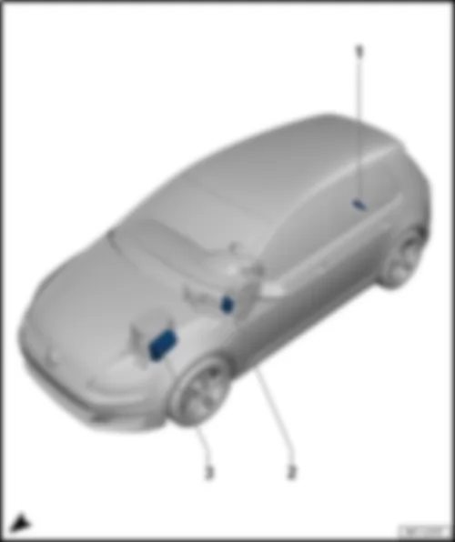
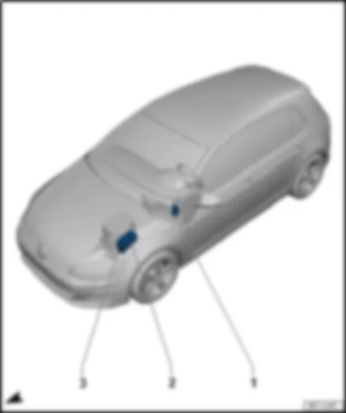
VW GOLF 2014 Overview of relay carriers

Overview of relay carriers
VW GOLF 2014 Overview of relay carriers https://portal-diagnostov.com/license.html
https://portal-diagnostov.com/license.html Automotive Electricians Portal FZCO Automotive Electricians Portal FZCO
Get access to all wiring diagrams of the carDownload PDF file
1 -  Not assigned
2 -  Relay and fuse carrier 2 -SR2- , on left under dash panel
t  Relay for reducing agent metering system -J963-
t  Terminal 15 relief relay -J404-
t  Heated rear window relay -J9-
t  Terminal 15 voltage supply relay -J329-
t  Relay for power sockets -J807-
q   Fitting locations and relay assignment, from January 2014
3 -  Relay and fuse carrier 1 -SR1- , on E-box in engine compartment
t  Automatic glow period control unit -J179-
t  Main relay -J271-
t  Terminal 30 voltage supply relay -J317-
t  Low heat output relay -J359-
t  High heat output relay -J360-
t  Horn relay -J413-
t  Engine component current supply relay -J757-
t  Starter relay 1 -J906-
t  Starter relay 2 -J907-
t  Fuel pump relay -J17-
q   Fitting location and relay assignment, equipment version 1, from January 2014
q   Fitting location and relay assignment, equipment version 2, from January 2014


VW GOLF 2014

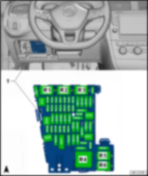
Relay and fuse carrier 2 -SR2- , on left under dash panel
Fitting location and relay assignment of relay and fuse carrier 2 -SR2- , from January 2014
VW GOLF 2014 https://portal-diagnostov.com/license.html
https://portal-diagnostov.com/license.html Automotive Electricians Portal FZCO Automotive Electricians Portal FZCO
Get access to all wiring diagrams of the carDownload PDF file
1 -  Relay and fuse carrier 2 -SR2- , on left under dash panel
R1 -  Relay for reducing agent metering system -J963-
q   Only models with reducing agent metering system
R2 -  Terminal 15 relief relay -J404-
q   Depending on equipment
R3 -  Not assigned
R4 -  Terminal 15 voltage supply relay -J329-
R5 -  Heated rear window relay -J9-
R6 -  Relay for power sockets -J807-

Back to overview
   
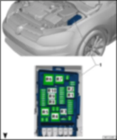
Fitting location and relay assignment of relay and fuse carrier 1 -SR1- , on E-box, equipment version 1, from January 2014
VW GOLF 2014 https://portal-diagnostov.com/license.html
https://portal-diagnostov.com/license.html Automotive Electricians Portal FZCO Automotive Electricians Portal FZCO
Get access to all wiring diagrams of the carDownload PDF file
1 -  Relay and fuse carrier 1 -SR1- , on E-box in engine compartment
R1 -  Starter relay 1 -J906-
R2 -  Starter relay 2 -J907-
R3 -  Horn relay -J413-
R4 -  High heat output relay -J360-
q   Only models with auxiliary air heater
R5 -  Main relay -J271-
q   Only models with petrol engine
R5 -  Terminal 30 voltage supply relay -J317-
q   Only models with a diesel engine
R6 -  Automatic glow period control unit -J179-
q   Only models with a diesel engine
R7 -  Low heat output relay -J359-
q   Only models with auxiliary air heater
R8 -  Fuel pump relay -J17-
q   Only models with MPI petrol engine
R9 -  Not assigned
R11 -  Not assigned

Back to overview
   
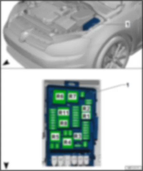
Fitting location and relay assignment of relay and fuse carrier 1 -SR1- , on E-box, equipment version 2, from January 2014
VW GOLF 2014 https://portal-diagnostov.com/license.html
https://portal-diagnostov.com/license.html Automotive Electricians Portal FZCO Automotive Electricians Portal FZCO
Get access to all wiring diagrams of the carDownload PDF file
1 -  Relay and fuse carrier 1 -SR1- , on E-box in engine compartment
R1 -  Starter relay 1 -J906-
R2 -  Starter relay 2 -J907-
R3 -  Horn relay -J413-
R4 -  High heat output relay -J360-
q   Only models with auxiliary air heater
R5 -  Main relay -J271-
q   Only models with petrol engine
R5 -  Terminal 30 voltage supply relay -J317-
q   Only models with a diesel engine
R6 -  Automatic glow period control unit -J179-
q   Only models with a diesel engine
R7 -  Low heat output relay -J359-
q   Only models with auxiliary air heater
R8 -  Engine component current supply relay -J757-
q   Depending on equipment
R11 -  Not assigned

Back to overview


VW GOLF 2014 Overview of fuse holder

Overview of fuse holder
VW GOLF 2014 Overview of fuse holder https://portal-diagnostov.com/license.html
https://portal-diagnostov.com/license.html Automotive Electricians Portal FZCO Automotive Electricians Portal FZCO
Get access to all wiring diagrams of the carDownload PDF file
q   Fuse assignment, from January 2014


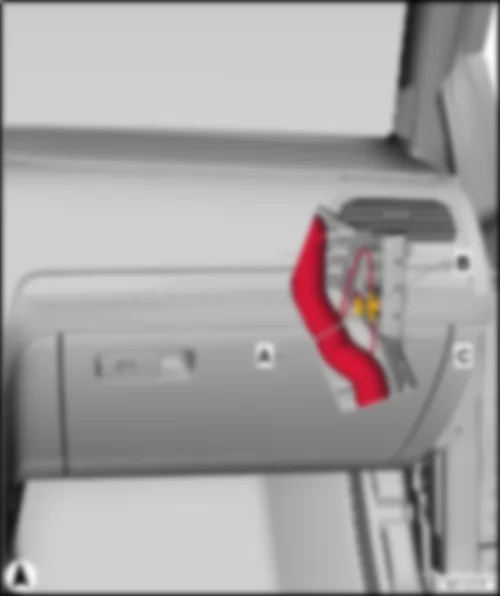
VW GOLF 2014 Fitting location fuse holder C SC

Fitting location fuse holder C -SC-
VW GOLF 2014 Fitting location fuse holder C SC https://portal-diagnostov.com/license.html
https://portal-diagnostov.com/license.html Automotive Electricians Portal FZCO Automotive Electricians Portal FZCO
Get access to all wiring diagrams of the carDownload PDF file
1 -  Fuse holder C -SC-
Fuse colours for J-Case fuse:
t  50 A - red
t  40 A - green
t  30 A - pink
Fuse colours for ATO flat fuse:
t  40 A - orange
t  30 A - light green
t  25 A - natural (white)
t  20 A - yellow
t  15 A - light blue
t  10 A - red
t  7.5 A - brown
t  5 A - light brown
t  1 A - black
Fuse colours for mini fuse:
t  20 A - yellow
t  15 A - light blue
t  10 A - red
t  7.5 A - brown
t  5 A - light brown
t  1 A - black

Back to overview


VW GOLF 2014

Fuse assignment fuse holder C -SC- , from January 2014
Slot Current Flow Diagram designation Nominal value Function/component Terminal
F1 Fuse 1 on fuse holder C -SC1- 30 A Coupling point in luggage compartment, centre6) 30
F2 Fuse 2 on fuse holder C -SC2- 15 A Steering column electronics control unit -J527-5) 30
F3 Fuse 3 on fuse holder C -SC3- - Special vehicle fuse/depending on equipment -
F4 Fuse 4 on fuse holder C -SC4- 10 A Onboard supply control unit -J519-
t  Anti-theft alarm system
30
F5 Fuse 5 on fuse holder C -SC5- 5 A Data bus diagnostic interface -J533- 30
F6 Not assigned -  
F7 Fuse 7 on fuse holder C -SC7- 10 A Heater and air conditioning controls -EX21- 30
    Heater control unit -J65-  
    Climatronic control unit -J255-  
    Air conditioning system control unit -J301-  
    Selector lever -E313-
      Heated rear window relay -J9-
F8 Fuse 8 on fuse holder C -SC8- 10 A Rotary light switch -EX1- 30
    Electromechanical parking brake button -E538-  
    Air humidity, rain and light sensor -G823-
      Diagnostic connection -U31-
F9 Fuse 9 on fuse holder C -SC9- 1 A Steering column electronics control unit -J527- 30
F10 Fuse 10 on fuse holder C -SC10- 10 A Display unit for front information display and operating unit control unit -J685- 30
F11 Not assigned - -
F12 Fuse 12 on fuse holder C -SC12- 20 A Control unit 1 for information electronics -J794- 30
F13 Fuse 13 on fuse holder C -SC13- 15 A Electronically controlled damping control unit -J250- 30
F14 Fuse 14 on fuse holder C -SC14- 30 A Fresh air blower control unit -J126- 30
F15 Fuse 15 on fuse holder C -SC15- 10 A Control unit for electronic steering column lock -J764- 30
F16 Fuse 16 on fuse holder C -SC16- 7.5 A Storage compartment with interface for mobile telephone -R265- 30
F17 Fuse 17 on fuse holder C -SC17- 5 A Control unit in dash panel insert -J285- 30
    Dash panel insert -KX2-  
      Navigation system interface -R94-
F18 Fuse 18 on fuse holder C -SC18- 7.5 A Reversing camera -R189- 30
      Rear lid handle release button -E234-  
F19 Fuse 19 on fuse holder C -SC19- 7.5 A Interface for entry and start system -J965- 30
F20 Fuse 20 on fuse holder C -SC20- 5 A Control unit for fuel tank leak detection -J909- 30
      Relay for reducing agent metering system -J963-6)  
F21 Not assigned - -
F22 Not assigned - -
F23 Fuse 23 on fuse holder C -SC23- 40 A Onboard supply control unit -J519-
t  Front right headlight -MX2-
30
F24 Fuse 24 on fuse holder C -SC24- 30 A Sliding sunroof adjustment control unit -J245- 30
F25 Fuse 25 on fuse holder C -SC25- 30 A Driver door control unit -J386- 30
    Rear left window regulator motor -V26- 30
F26 Fuse 26 on fuse holder C -SC26- 30 A Onboard supply control unit -J519-
t  Front heated seats
30
F27 Fuse 27 on fuse holder C -SC27- 30 A Digital sound package control unit -J525- 30
F28 Fuse 28 on fuse holder C -SC28- 20 A Trailer detector control unit -J345- 30
F29 Fuse 29 on fuse holder C -SC29- - Special vehicle fuse/depending on equipment -
F30 Not assigned - -
F31 Fuse 31 on fuse holder C -SC31- 40 A Onboard supply control unit -J519-
t  Front left headlight -MX1-
30
F32 Fuse 32 on fuse holder C -SC32- 7.5 A Adaptive cruise control unit -J428- 15
    Parking aid control unit -J446-
F33 Fuse 33 on fuse holder C -SC33- 5 A Airbag control unit -J234- 15
      Front passenger front airbag deactivated warning lamp -K145-  
F34 Fuse 34 on fuse holder C -SC34- 7.5 A Rotary light switch -EX1- 15
    Interior mirror -EX5-  
    Relay for power sockets -J807-  
    Reversing light switch -F4-
    Pressure sender for refrigerant circuit -G805-
    Air quality sensor -G238-
    Control unit for structure-borne sound -J869-4)
    TCS and ESP button -E256-  
F35 Fuse 35 on fuse holder C -SC35- 10 A Diagnostic connection -U31- 15
    Headlight range control and instrument illumination regulator -EX14-  
    Control unit for cornering light and headlight range control -J745-
    Left headlight range control motor -V48-
      Right headlight range control motor -V49-  
F36 Fuse 36 on fuse holder C -SC36- 10 A Control unit for right daytime running light and side light -J861- 15
F37 Fuse 37 on fuse holder C -SC37- 10 A Control unit for left daytime running light and side light -J860- 15
F38 Fuse 38 on fuse holder C -SC38- 20 A Trailer detector control unit -J345- 30
F39 Fuse 39 on fuse holder C -SC39- 30 A Front passenger door control unit -J387- 30
    Rear right window regulator motor -V27-
F40 2) , 3) Fuse 40 on fuse holder C -SC40- 20 A Cigarette lighter -U1- 1) 15 2) / 30 3)
    12 V socket -U5-  
      12 V socket 2 -U18-  
F41 Not assigned - - -
F42 Fuse 42 on fuse holder C -SC42- 40 A Onboard supply control unit -J519-
t  Central locking
30
F43 Fuse 43 on fuse holder C -SC43- 30 A Onboard supply control unit -J519- 30
F44 Fuse 44 on fuse holder C -SC44- 15 A Trailer detector control unit -J345- 30
F45 Fuse 45 on fuse holder C -SC45- 15 A Driver seat lumbar support adjustment switch -E176- 30
    Driver seat adjustment operating unit -E470-
F46 Not assigned - -
F47 Fuse 47 on fuse holder C -SC47- 15 A Rear window wiper motor -V12- 15
F48 Not assigned - -
F49 Fuse 49 on fuse holder C -SC49- 5 A Clutch position sender -G476- 15
    Starter relay 1 -J906-  
      Starter relay 2 -J907-  
F50 Not assigned - -
F51 Not assigned - -
F52 Not assigned - -
F53 Fuse 53 on fuse holder C -SC53- 30 A Heated rear window relay -J9- 15

1) Smokers version
2) Factory fitted with power supply from terminal 15
3) Power supply via terminal 30 possible
4) Only GTI models
5) Only models with heated steering wheel
6) Only models with reducing agent metering system
  Note
The fuse SC40 is supplied via terminal 15 from the factory and can be supplied via terminal 30 by reconnecting. If a consumer is connected to the electric socket or to the cigarette lighter, ensure that the consumer is disconnected from the voltage supply when the engine is switched off to prevent the drive battery being discharged.
Back to overview


VW GOLF 2014 Fitting location fuse holder B SB

Fitting location fuse holder B -SB-
VW GOLF 2014 Fitting location fuse holder B SB https://portal-diagnostov.com/license.html
https://portal-diagnostov.com/license.html Automotive Electricians Portal FZCO Automotive Electricians Portal FZCO
Get access to all wiring diagrams of the carDownload PDF file
1 -  Fuse holder B -SB-
Fuse colours for J-Case fuse:
t  50 A - red
t  40 A - green
t  30 A - pink
Fuse colours for ATO flat fuse:
t  40 A - orange
t  30 A - light green
t  25 A - natural (white)
t  20 A - yellow
t  15 A - light blue
t  10 A - red
t  7.5 A - brown
t  5 A - light brown
t  1 A - black

Back to overview


VW GOLF 2014

Fuse assignment fuse holder B -SB- , January 2014
Slot Current Flow Diagram designation Nominal value Function/component Terminal
F1 Fuse 1 on fuse holder B -SB1- 40 A ABS control unit -J104- 30
F2 Fuse 2 on fuse holder B -SB2- 40 A ABS control unit -J104- 30
      ABS hydraulic pump -V64-
F3 Fuse 3 on fuse holder B -SB3- 15 A 1)
30 A 2)
Engine control unit -J623- 87
F4 Fuse 4 on fuse holder B -SB4- 5 A 2)
10 A 1)
Oil level and oil temperature sender -G266- 87
    Radiator fan control unit -J293-  
    Activated charcoal filter solenoid valve 1 -N80- 1)
    Camshaft control valve 1 -N205-1)
    Exhaust camshaft control valve 1 -N318- 1)  
    Valve for oil pressure control -N428- 1)  
    High heat output relay -J360- 2)  
    Exhaust gas recirculation cooler changeover valve -N345- 2)  
    Low heat output relay -J359- 2)  
    Charge pressure control solenoid valve -N75- 2)  
    Inlet cam actuator for cylinder 2 -N583- 1)
    Exhaust cam actuator for cylinder 2 -N587- 1)
    Inlet cam actuator for cylinder 3 -N591- 1)
    Exhaust cam actuator for cylinder 3 -N595- 1)
    Ethanol concentration sender -G708- 1)  
    Turbocharger air recirculation valve -N249-4)
    Intake manifold flap valve -N316-4)
      Piston cooling jet control valve -N522-4)
F5 Fuse 5 on fuse holder B -SB5- 10 A 2) Fuel pressure regulating valve -N276- 87
    Fuel metering valve -N290-
    Engine component current supply relay -J757-4)
F6 Fuse 6 on fuse holder B -SB6- 5 A Brake light switch -F- 87
F7 Fuse 7 on fuse holder B -SB7- 7.5 A 1)
10 A 2)
Fuel pressure regulating valve -N276- 1) 87
    Charge air cooling pump -V188- 1)  
    Valve for oil pressure control -N428-2)  
    Solenoid for coolant circuit -N492-2)  
    Charge air cooling pump -V188- 2)  
    Gearbox oil cooling pump -V478-4)  
    Coolant shut-off valve -N82-4)
    Auxiliary pump for heating -V488- 2)  
      Radiator blind control motor -V544-2)  
F8 Fuse 8 on fuse holder B -SB8- 10 A 1)
15 A 2)
Lambda probe heater -Z19- 87
    Lambda probe 1 before catalytic converter -GX10-  
    Lambda probe 1 heater after catalytic converter -Z29-  
      Lambda probe 1 after catalytic converter -GX7-
F9 Fuse 9 on fuse holder B -SB9- 5 A 2)
20 A 1)
Ignition coil 1 with output stage -N70- 1) 87
    Ignition coil 2 with output stage -N127-1)  
    Ignition coil 3 with output stage -N291- 1)
    Ignition coil 4 with output stage -N292-1)  
    Automatic glow period control unit -J179- 2)  
    Air mass meter -G70-  
    Intake manifold preheating heater element -N51- 2)  
  10A 1) Exhaust flap control unit -J883- 1)  
    Sender 1 for secondary air pressure -G609- 1)  
    Charge air cooling pump -V188- 1)  
    Activated charcoal filter solenoid valve 1 -N80- 1)  
    Camshaft control valve 1 -N205- 1)  
    Exhaust camshaft control valve 1 -N318- 1)  
F10 Fuse 10 on fuse holder B -SB10- 10 A 1)
20 A 2)
Fuel pump control unit -J538- 87
F11 Fuse 11 on fuse holder B -SB11- 40 A Auxiliary air heater element -Z35- 87
F12 Fuse 12 on fuse holder B -SB12- 40 A Auxiliary air heater element -Z35- 87
F13 Fuse 13 on fuse holder B -SB13- 30 A Automatic gearbox control unit -J217- 30
    Mechatronic unit for dual clutch gearbox -J743-
   
t  Dual clutch gearbox 200
 
  15 A Mechatronic unit for dual clutch gearbox -J743-
     
t  Dual clutch gearbox 250
 
F14 Not assigned -  
F15 Fuse 15 on fuse holder B -SB15- 15 A Horn relay -J413- 30
F16 Fuse 16 on fuse holder B -SB16- 20 A Engine component current supply relay -J757-4) 30
F17 Fuse 17 on fuse holder B -SB17- 7.5 A Main relay -J271- 1) 30
    Terminal 30 voltage supply relay -J317- 2)
    Engine control unit -J623-  
    ABS control unit -J104-  
      Heated windscreen relay -J47-
F18 Fuse 18 on fuse holder B -SB18- 5 A Battery monitoring control unit -J367- 30
      Data bus diagnostic interface -J533- 3)
F19 Fuse 19 on fuse holder B -SB19- 30 A Wiper motor control unit -J400- 30
F20 Not assigned - -
F21 Not assigned - -
F22 Fuse 22 on fuse holder B -SB22- 5 A Engine control unit -J623- 50
F23 Fuse 23 on fuse holder B -SB23- 30 A Starter -B- 50
F24 Fuse 24 on fuse holder B -SB24- 40 A Auxiliary air heater element -Z35- 87
F25 Not assigned - -
F26 Not assigned - -
F27 Not assigned - -
F28 Not assigned - -
F29 Not assigned - -
F30 Not assigned - -
F31 Not assigned - -
F32 Not assigned - -
F33 Not assigned - -
F34 Fuse 34 on fuse holder B -SB34- 15 A Axle differential lock control unit -J647-4) 30
F35 Not assigned - -
F36 Not assigned - -
F37 Not assigned - -
F38 Not assigned - -

1) Only models with petrol engine
2) Only models with diesel engine
3) Only models with no start/stop system
4) Only GTI models
Back to overview


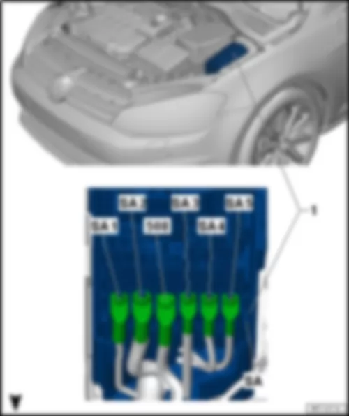
VW GOLF 2014 Fitting location fuse holder A SA

Fitting location fuse holder A -SA-
VW GOLF 2014 Fitting location fuse holder A SA https://portal-diagnostov.com/license.html
https://portal-diagnostov.com/license.html Automotive Electricians Portal FZCO Automotive Electricians Portal FZCO
Get access to all wiring diagrams of the carDownload PDF file
1 -  Fuse holder A -SA-
508 -  Threaded connection (30) on E-box

Multifuse strip fuse
→ Repair Group  97
  Note
The strip fuse (Multifuse) must be replaced as a complete unit.
Back to overview


VW GOLF 2014

Fuse assignment fuse holder A -SA- , January 2014
Screw location Current Flow Diagram designation Nominal value Function/component Terminal
J1 Fuse 1 on fuse holder A -SA1- 125 A Supply for fuses: 30
      -SC4- …-SC14-  
      -SC30-  
      -SC31-  
      -SC38-  
      -SC39-  
      -SC41-  
      -SC42-  
      -SC53-  
  Terminal 15 voltage supply relay -J329-
G1 Fuse 2 on fuse holder A -SA2- 400 A Alternator -C- 30
E1 Fuse 3 on fuse holder A -SA3- 80 A Power steering control unit -J500- 30
K1 Fuse 4 on fuse holder A -SA4- 80 A Supply for fuses: 30
      -SC15- …-SC20-  
      -SC23- …-SC28-  
    -SB43- …-SB45-  
L1 Fuse 5 on fuse holder A -SA5- 50 A Radiator fan -VX57- 30

Back to overview


VW GOLF 2014

10-pin connector -T10kv- , black / 10-pin connector -T10kw- , black

VW GOLF 2014 Coupling point in engine compartment, left TML

Coupling point in engine compartment, left -TML-
VW GOLF 2014 Coupling point in engine compartment, left TML https://portal-diagnostov.com/license.html
https://portal-diagnostov.com/license.html Automotive Electricians Portal FZCO Automotive Electricians Portal FZCO
Get access to all wiring diagrams of the carDownload PDF file
10-pin connector -T10kv- , black / 10-pin connector -T10kw- , black
q   Only models with a diesel engine
6-pin connector -T6cj- , black / 6-pin connector -T6cq- , black
q   Only models with petrol engine
10-pin connector -T10ky- , black / 10-pin connector -T10kx- , black
q   Only models with diesel engines
14-pin connector -T14i- , grey / 14-pin connector -T14h- , grey
14-pin connector -T14l- , grey / 14-pin connector -T14m- , grey
q   Only models with 2.0l petrol engine
8-pin connector -T8at- , black / 8-pin connector -T8as- , black
q   Only models with 2.0l diesel engine
q   Only models with 2.0l petrol engine without gearbox oil cooling pump -V478-
10-pin connector -T10ag- , black / 10-pin connector -T10af- , black
q   Only models with 2.0l petrol engine with gearbox oil cooling pump -V478-
8-pin connector -T8au- , black / 8-pin connector -T8az- , black
4-pin connector -T4x- , black / 4-pin connector -T4f- , black
6-pin connector -T6as- , black / 6-pin connector -T6at- , black
q   Only models with axle differential lock control unit -J647-

   
Coupling point on engine, top centre -TMOM-
VW GOLF 2014 Coupling point in engine compartment, left TML https://portal-diagnostov.com/license.html
https://portal-diagnostov.com/license.html Automotive Electricians Portal FZCO Automotive Electricians Portal FZCO
Get access to all wiring diagrams of the carDownload PDF file
8-pin connector -T8h- / 8-pin connector -T8i-

   
Coupling point on engine, top right -TMOR-
VW GOLF 2014 Coupling point in engine compartment, left TML https://portal-diagnostov.com/license.html
https://portal-diagnostov.com/license.html Automotive Electricians Portal FZCO Automotive Electricians Portal FZCO
Get access to all wiring diagrams of the carDownload PDF file
8-pin connector -T8f- / 8-pin connector -T8g-
14-pin connector -T14e- / 14-pin connector -T14f-

   
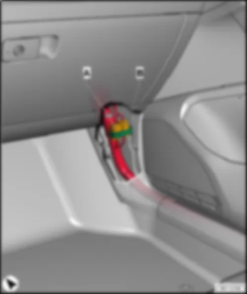
Diagnostic connection -U31-
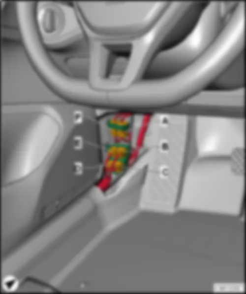
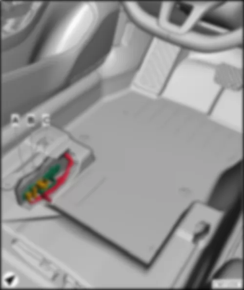
VW GOLF 2014 Coupling point in engine compartment, left TML https://portal-diagnostov.com/license.html
https://portal-diagnostov.com/license.html Automotive Electricians Portal FZCO Automotive Electricians Portal FZCO
Get access to all wiring diagrams of the carDownload PDF file
A -  16-pin connector -T16- , black

   
Coupling point on front left door -TTVL-
VW GOLF 2014 Coupling point in engine compartment, left TML https://portal-diagnostov.com/license.html
https://portal-diagnostov.com/license.html Automotive Electricians Portal FZCO Automotive Electricians Portal FZCO
Get access to all wiring diagrams of the carDownload PDF file
27-pin connector -T27- , black / 27-pin connector -T27b- , black

   
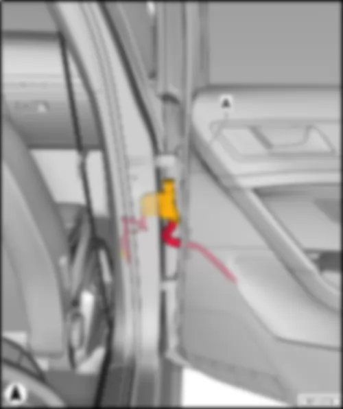
Coupling point on rear left door -TTHL-
VW GOLF 2014 Coupling point in engine compartment, left TML https://portal-diagnostov.com/license.html
https://portal-diagnostov.com/license.html Automotive Electricians Portal FZCO Automotive Electricians Portal FZCO
Get access to all wiring diagrams of the carDownload PDF file
19-pin connector -T19b- , black / 19-pin connector -T19c- , black

   
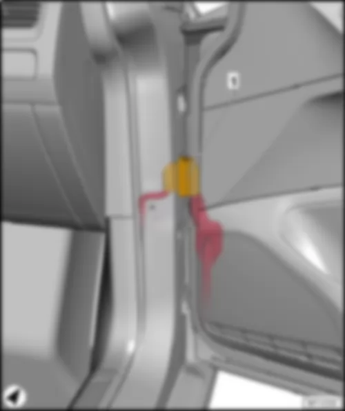
Coupling point in interior, below left -TIUL-
VW GOLF 2014 Coupling point in engine compartment, left TML https://portal-diagnostov.com/license.html
https://portal-diagnostov.com/license.html Automotive Electricians Portal FZCO Automotive Electricians Portal FZCO
Get access to all wiring diagrams of the carDownload PDF file
17-pin connector -T17h- , green / 17-pin connector -T17q- , green
17-pin connector -T17e- , brown / 17-pin connector -T17m- , brown
17-pin connector -T17g- , blue / 17-pin connector -T17o- , blue
17-pin connector -T17f- , red / 17-pin connector -T17n- , red
17-pin connector -T17d- , black / 17-pin connector -T17l- , black
17-pin connector -T17j- , white / 17-pin connector -T17p- , white

   
Coupling point for front left seat -TSVL-
VW GOLF 2014 Coupling point in engine compartment, left TML https://portal-diagnostov.com/license.html
https://portal-diagnostov.com/license.html Automotive Electricians Portal FZCO Automotive Electricians Portal FZCO
Get access to all wiring diagrams of the carDownload PDF file
2-pin connector -T2fw- , black / 2-pin connector -T2fx- , black
3-pin connector -T3cy- , yellow / 3-pin connector -T3cz- , yellow
10-pin connector -T10a- , black / 10-pin connector -T10w- , black

   
Coupling point for roof -TH-
VW GOLF 2014 Coupling point in engine compartment, left TML https://portal-diagnostov.com/license.html
https://portal-diagnostov.com/license.html Automotive Electricians Portal FZCO Automotive Electricians Portal FZCO
Get access to all wiring diagrams of the carDownload PDF file
16-pin connector -T16j- / 16-pin connector -T16k-

   
Coupling point for roof, centre -THM-
VW GOLF 2014 Coupling point in engine compartment, left TML https://portal-diagnostov.com/license.html
https://portal-diagnostov.com/license.html Automotive Electricians Portal FZCO Automotive Electricians Portal FZCO
Get access to all wiring diagrams of the carDownload PDF file
6-pin connector -T6cr- / 6-pin connector -T6cp-

   
Coupling point on front right door -TTVR-
VW GOLF 2014 Coupling point in engine compartment, left TML https://portal-diagnostov.com/license.html
https://portal-diagnostov.com/license.html Automotive Electricians Portal FZCO Automotive Electricians Portal FZCO
Get access to all wiring diagrams of the carDownload PDF file
27-pin connector -T27a- , black / 27-pin connector -T27c- , black

   
Coupling point on rear right door -TTHR-
VW GOLF 2014 Coupling point in engine compartment, left TML https://portal-diagnostov.com/license.html
https://portal-diagnostov.com/license.html Automotive Electricians Portal FZCO Automotive Electricians Portal FZCO
Get access to all wiring diagrams of the carDownload PDF file
19-pin connector -T19- , black / 19-pin connector -T19a- , black

   
Coupling point in interior, below right -TIUR-
VW GOLF 2014 Coupling point in engine compartment, left TML https://portal-diagnostov.com/license.html
https://portal-diagnostov.com/license.html Automotive Electricians Portal FZCO Automotive Electricians Portal FZCO
Get access to all wiring diagrams of the carDownload PDF file
17-pin connector -T17k- , brown / 17-pin connector -T17s- , brown
17-pin connector -T17i- , black / 17-pin connector -T17r- , black

   
VW GOLF 2014 Coupling point in engine compartment, left TML https://portal-diagnostov.com/license.html
https://portal-diagnostov.com/license.html Automotive Electricians Portal FZCO Automotive Electricians Portal FZCO
Get access to all wiring diagrams of the carDownload PDF file
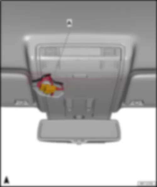
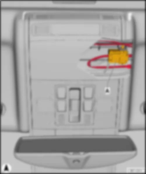
B -  2-pin connector -T2es- , black
Coupling point for front right seat -TSVR-
VW GOLF 2014 Coupling point in engine compartment, left TML https://portal-diagnostov.com/license.html
https://portal-diagnostov.com/license.html Automotive Electricians Portal FZCO Automotive Electricians Portal FZCO
Get access to all wiring diagrams of the carDownload PDF file
2-pin connector -T2gr- , black / 2-pin connector -T2gs- , black
q   Depending on equipment
10-pin connector -T10b- , black / 10-pin connector -T10x- , black
3-pin connector -T3db- , yellow / 3-pin connector -T3dc- , yellow
4-pin connector -T4ee- , black / 4-pin connector -T4ef- , black
q   Depending on equipment

   
Coupling point on rear lid -THK-
VW GOLF 2014 Coupling point in engine compartment, left TML https://portal-diagnostov.com/license.html
https://portal-diagnostov.com/license.html Automotive Electricians Portal FZCO Automotive Electricians Portal FZCO
Get access to all wiring diagrams of the carDownload PDF file
10-pin connector -T10l- , brown / 10-pin connector -T10n- , brown
10-pin connector -T10d- , black / 10-pin connector -T10p- , black

   
Coupling point in luggage compartment, left -THRL-
VW GOLF 2014 Coupling point in engine compartment, left TML https://portal-diagnostov.com/license.html
https://portal-diagnostov.com/license.html Automotive Electricians Portal FZCO Automotive Electricians Portal FZCO
Get access to all wiring diagrams of the carDownload PDF file
8-pin connector -T8aw- , black / 8-pin connector -T8ba- , black

   
Coupling point in luggage compartment, right -THRR-
VW GOLF 2014 Coupling point in engine compartment, left TML https://portal-diagnostov.com/license.html
https://portal-diagnostov.com/license.html Automotive Electricians Portal FZCO Automotive Electricians Portal FZCO
Get access to all wiring diagrams of the carDownload PDF file
2-pin connector -T2ca- , black / 2-pin connector -T2cb- , black
q   Depending on equipment
10-pin connector -T10la- , black / 10-pin connector -T10lf- , black
q   Depending on equipment

   
VW GOLF 2014VW GOLF 2014VW GOLF 2014VW GOLF 2014VW GOLF 2014VW GOLF 2014VW GOLF 2014VW GOLF 2014VW GOLF 2014VW GOLF 2014VW GOLF 2014VW GOLF 2014VW GOLF 2014VW GOLF 2014VW GOLF 2014VW GOLF 2014VW GOLF 2014VW GOLF 2014VW GOLF 2014VW GOLF 2014VW GOLF 2014VW GOLF 2014VW GOLF 2014VW GOLF 2014VW GOLF 2014VW GOLF 2014VW GOLF 2014VW GOLF 2014VW GOLF 2014VW GOLF 2014VW GOLF 2014VW GOLF 2014VW GOLF 2014VW GOLF 2014VW GOLF 2014VW GOLF 2014VW GOLF 2014VW GOLF 2014VW GOLF 2014VW GOLF 2014VW GOLF 2014VW GOLF 2014VW GOLF 2014VW GOLF 2014VW GOLF 2014VW GOLF 2014VW GOLF 2014VW GOLF 2014VW GOLF 2014VW GOLF 2014VW GOLF 2014VW GOLF 2014VW GOLF 2014VW GOLF 2014VW GOLF 2014VW GOLF 2014VW GOLF 2014VW GOLF 2014VW GOLF 2014VW GOLF 2014VW GOLF 2014VW GOLF 2014VW GOLF 2014VW GOLF 2014VW GOLF 2014VW GOLF 2014VW GOLF 2014VW GOLF 2014VW GOLF 2014VW GOLF 2014VW GOLF 2014VW GOLF 2014VW GOLF 2014VW GOLF 2014VW GOLF 2014VW GOLF 2014VW GOLF 2014VW GOLF 2014VW GOLF 2014VW GOLF 2014VW GOLF 2014VW GOLF 2014VW GOLF 2014VW GOLF 2014VW GOLF 2014VW GOLF 2014VW GOLF 2014VW GOLF 2014VW GOLF 2014VW GOLF 2014VW GOLF 2014VW GOLF 2014VW GOLF 2014VW GOLF 2014VW GOLF 2014VW GOLF 2014VW GOLF 2014VW GOLF 2014VW GOLF 2014VW GOLF 2014VW GOLF 2014VW GOLF 2014VW GOLF 2014VW GOLF 2014VW GOLF 2014VW GOLF 2014VW GOLF 2014VW GOLF 2014VW GOLF 2014VW GOLF 2014VW GOLF 2014VW GOLF 2014VW GOLF 2014VW GOLF 2014VW GOLF 2014VW GOLF 2014VW GOLF 2014VW GOLF 2014VW GOLF 2014VW GOLF 2014VW GOLF 2014VW GOLF 2014VW GOLF 2014VW GOLF 2014VW GOLF 2014VW GOLF 2014VW GOLF 2014VW GOLF 2014VW GOLF 2014VW GOLF 2014VW GOLF 2014VW GOLF 2014VW GOLF 2014VW GOLF 2014VW GOLF 2014VW GOLF 2014VW GOLF 2014VW GOLF 2014VW GOLF 2014VW GOLF 2014VW GOLF 2014VW GOLF 2014VW GOLF 2014VW GOLF 2014VW GOLF 2014VW GOLF 2014VW GOLF 2014VW GOLF 2014VW GOLF 2014VW GOLF 2014VW GOLF 2014VW GOLF 2014VW GOLF 2014VW GOLF 2014VW GOLF 2014VW GOLF 2014VW GOLF 2014VW GOLF 2014VW GOLF 2014VW GOLF 2014VW GOLF 2014VW GOLF 2014VW GOLF 2014VW GOLF 2014VW GOLF 2014VW GOLF 2014VW GOLF 2014VW GOLF 2014VW GOLF 2014VW GOLF 2014VW GOLF 2014VW GOLF 2014VW GOLF 2014VW GOLF 2014VW GOLF 2014VW GOLF 2014VW GOLF 2014VW GOLF 2014VW GOLF 2014VW GOLF 2014VW GOLF 2014VW GOLF 2014VW GOLF 2014VW GOLF 2014