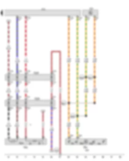
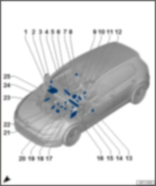
| EX21 | Heater and air conditioning controls |
| E653 | Button for left seat heating |
| E654 | Button for right seat heating |
| G345 | Front right seat temperature sender |
| J255 | Climatronic control unit |
| J519 | Onboard supply control unit |
| J533 | Data bus diagnostic interface |
| K59 | Heated driver seat warning lamp |
| K68 | Heated front passenger seat warning lamp |
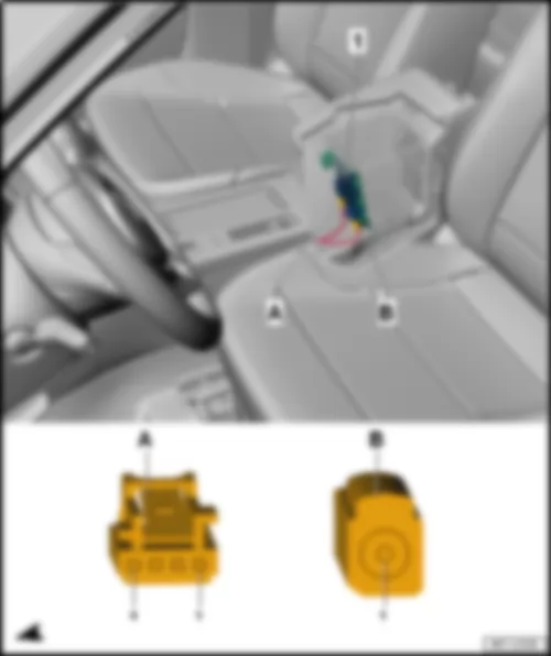
| T4aw | 4-pin connector |
| T4m | 4-pin connector |
| T10b | 10-pin connector, black |
| T10x | 10-pin connector, black |
| T20 | 20-pin connector |
| T20c | 20-pin connector |
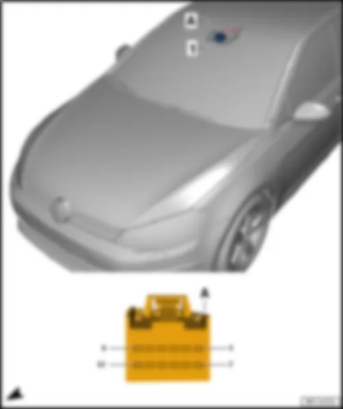
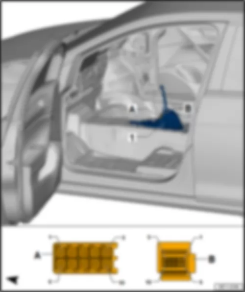
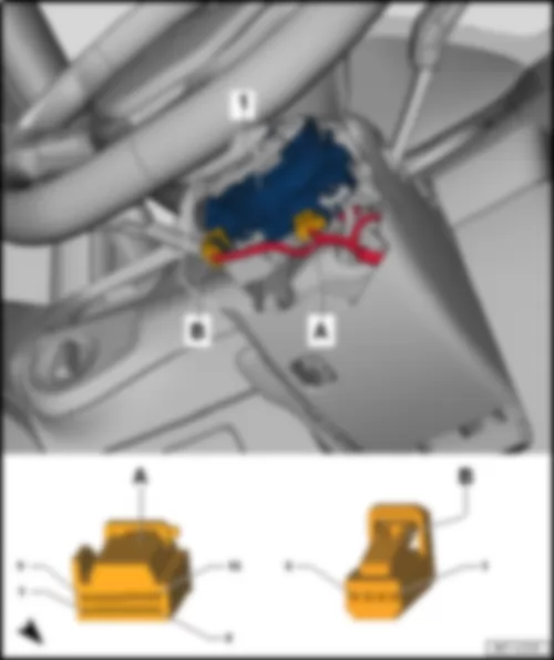
| T73a | 73-pin connector |
| T73c | 73-pin connector |
| TSVR | Coupling point for front right seat |
| VX62 | Front right seat pan |
| Z6 | Heated seat cushion for driver seat |
| Z8 | Heated seat cushion for front passenger seat |
| |
| B398 | Connection 2 (convenience CAN bus, high), in main wiring harness |
| B407 | Connection 2 (convenience CAN bus, low), in main wiring harness |
| B506 | Connection (convenience CAN bus, high), in interior wiring harness |
| B507 | Connection (convenience CAN bus, low), in interior wiring harness |
| * | Only left-hand drive models |
| *2 | Only right-hand drive models |
| *3 | Wiring colour depends on equipment |
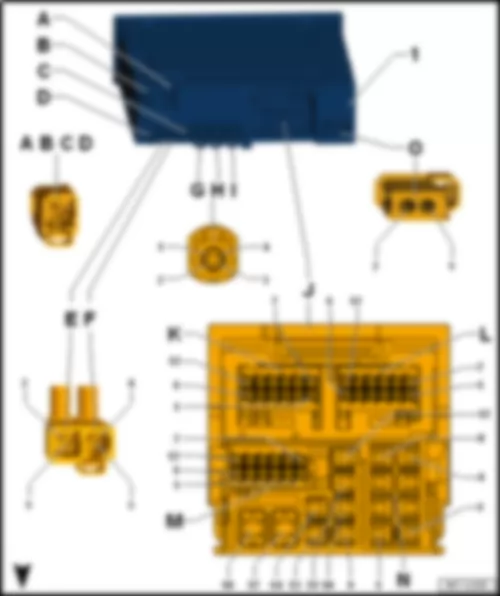
| -T12al- (M) | Designation | | -T12ag- (K) | Designation | | -T12a- (L) | Designation |
| 1 | B415 Connection 1 (infotainment CAN bus, high) in main wiring harness | | 1 | Interface for external multimedia unit -R215-1
Connection for external audio sources -R199-1 | | 1 | Telephone microphone -R38- |
| 2 | Display unit for front information display and operating unit control unit -J685- | | 2 | Interface for external multimedia unit -R215-1
Connection for external audio sources -R199-1 | | 2 | |
| 3 | | | 3 | Interface for external multimedia unit -R215-1
Connection for external audio sources -R199-1
USB hub -R293-1 | | 3 | |
| 4 | | | 4 | Interface for external multimedia unit -R215-1
Connection for external audio sources -R199-1 | | 4 | |
| 5 | Terminal 30 | | 5 | Interface for external multimedia unit -R215-1 | | 5 | |
| 6 | A178 Connection (infotainment CAN bus, high), in dash panel wiring harness | | 6 | Interface for external multimedia unit -R215-1 | | 6 | Reversing camera -R189- |
| 7 | B421 Connection 1 (infotainment CAN bus, low) in main wiring harness | | 7 | Interface for external multimedia unit -R215-1
Connection for external audio sources -R199-1 | | 7 | Telephone microphone -R38- , screening connection |
| 8 | Display unit for front information display and operating unit control unit -J685- | | 8 | Interface for external multimedia unit -R215-1
Connection for external audio sources -R199-1 | | 8 | |
| 9 | | | 9 | Interface for external multimedia unit -R215-1 | | 9 | |
| 10 | | | 10 | Interface for external multimedia unit -R215-1 | | 10 | |
| 11 | | | 11 | Interface for external multimedia unit -R215-1 | | 11 | |
| 12 | A179 Connection (infotainment CAN bus, low), in dash panel wiring harness | | 12 | Interface for external multimedia unit -R215-1 | | 12 | Reversing camera -R189- |
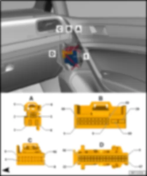
| -T6f- (A) | Designation | | -T20b- (B) | Designation | | -T16g- (C) | Designation | | -T32c- (D) | Designation |
| 1 | | | 1 | | | 1 | Front passenger side entry light in exterior mirror -W53- | | 1 | |
| 2 | | | 2 | | | 2 | | | 2 | |
| 3 | Right window regulator motor -V15- | | 3 | | | 3 | Front passenger side exterior mirror -VX5- | | 3 | Light for passenger door ambient lighting -W87- |
| 4 | | | 4 | | | 4 | Front passenger side exterior mirror -VX5- | | 4 | Kl.58 |
| 5 | | | 5 | Front passenger door contact switch -F3- | | 5 | Front passenger side exterior mirror -VX5- | | 5 | Terminal 31 |
| 6 | Right window regulator motor -V15- | | 6 | Front passenger door central locking actuator for SAFELOCK function -F244- | | 6 | | | 6 | |
| | | | 7 | | | 7 | Front passenger side mirror adjustment motor -V25- | | 7 | |
| | | | 8 | | | 8 | Front passenger side mirror adjustment motor -V150- | | 8 | Light for passenger door ambient lighting -W87- |
| | | | 9 | | | 9 | Front passenger side fold-in mirror motor -V122- | | 9 | |
| | | | 10 | Rear right window regulator motor -V27- | | 10 | Front passenger side fold-in mirror motor -V122- | | 10 | |
| | | | 11 | Front passenger door lock unit -VX22- | | 11 | Front passenger side turn signal repeater bulb -L132- | | 11 | |
| | | | 12 | Front passenger door central locking SAFELOCK function motor -V162- | | 12 | | | 12 | |
| | | | 13 | Front passenger door central locking motor -V57- | | 13 | Front passenger side exterior mirror -VX5- | | 13 | Central locking button -E600- |
| | | | 14 | B407 Connection 2 (convenience CAN bus, low) in main wiring harness | | 14 | Front passenger side exterior mirror -VX5- | | 14 | |
| | | | 15 | B398 Connection 2 (convenience CAN bus, high) in main wiring harness | | 15 | Heated exterior mirror on front passenger side -Z5- | | 15 | |
| | | | 16 | | | 16 | Front passenger side exterior mirror -VX5- | | 16 | Light conductor for front right sill panel moulding ambient lighting -W68- |
| | | | 17 | | | | | | 17 | |
| | | | 18 | | | | | | 18 | |
| | | | 19 | Terminal 30 | | | | | 19 | |
| | | | 20 | Terminal 31 | | | | | 20 | |
| | | | | | | | | | 21 | |
| | | | | | | | | | 22 | |
| | | | | | | | | | 23 | |
| | | | | | | | | | 24 | |
| | | | | | | | | | 25 | |
| | | | | | | | | | 26 | |
| | | | | | | | | | 27 | |
| | | | | | | | | | 28 | |
| | | | | | | | | | 29 | |
| | | | | | | | | | 30 | |
| | | | | | | | | | 31 | |
| | | | | | | | | | 32 | Front passenger side window regulator button -E716- |
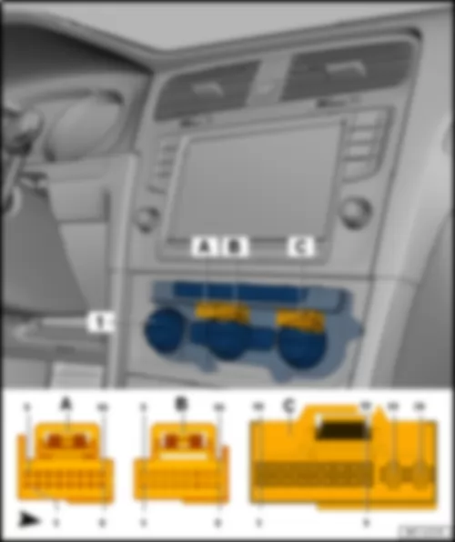
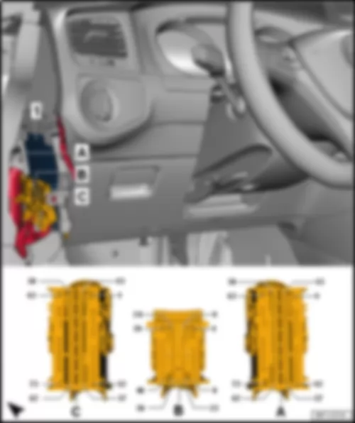
| -T16d- (A) | Designation | | -T16c- (B) | Designation | | -T20c- (C) | Designation |
| 1 | Left temperature flap control motor -V158- | | 1 | Potentiometer for front air distribution flap control motor -G642-
Potentiometer for fresh air/air recirculation, air flow flap control motor -G644-
Potentiometer for defroster flap control motor -G135-
Potentiometer for left temperature flap control motor -G220-
Potentiometer for right temperature flap control motor -G221- | | 1 | Sunlight penetration photosensor -G107- |
| 2 | Left temperature flap control motor -V158- | | 2 | Potentiometer for left temperature flap control motor -G220- | | 2 | |
| 3 | Defroster flap control motor -V107- | | 3 | Potentiometer for right temperature flap control motor -G221- | | 3 | Sunlight penetration photosensor -G107- |
| 4 | Defroster flap control motor -V107- | | 4 | Potentiometer for defroster flap control motor -G135- | | 4 | |
| 5 | Front air distribution flap control motor -V426- | | 5 | Potentiometer for front air distribution flap control motor -G642- | | 5 | B506 Connection (convenience CAN bus, high) in interior wiring harness |
| 6 | Front air distribution flap control motor -V426- | | 6 | | | 6 | B507 Connection (convenience CAN bus, low) in interior wiring harness |
| 7 | | | 7 | Potentiometer for fresh air/air recirculation, air flow flap control motor -G644- | | 7 | |
| 8 | | | 8 | Footwell vent temperature sender -G192- | | 8 | |
| 9 | Fresh air/air recirculation, air flow flap control motor -V425- | | 9 | | | 9 | Sunlight penetration photosensor -G107- |
| 10 | Fresh air/air recirculation, air flow flap control motor -V425- | | 10 | | | 10 | |
| 11 | Right temperature flap control motor -V159- | | 11 | Evaporator temperature sensor -G308- | | 11 | |
| 12 | Right temperature flap control motor -V159- | | 12 | | | 12 | |
| 13 | | | 13 | | | 13 | Left vent temperature sender -G150- |
| 14 | | | 14 | Potentiometer for front air distribution flap control motor -G642-
Potentiometer for fresh air/air recirculation, air flow flap control motor -G644-
Potentiometer for defroster flap control motor -G135-
Potentiometer for left temperature flap control motor -G220-
Potentiometer for right temperature flap control motor -G221-
Footwell vent temperature sender -G192-
Evaporator temperature sensor -G308- | | 14 | Right vent temperature sender -G151- |
| 15 | | | 15 | | | 15 | |
| 16 | | | 16 | | | 16 | A209 Connection 1 (LIN bus) in dash panel wiring harness |
| | | | | | | 17 | Sunlight penetration photosensor -G107-
Right vent temperature sender -G151-
Left vent temperature sender -G150- |
| | | | | | | 18 | Air conditioning system relay -J32- |
| | | | | | | 19 | Terminal 31 |
| | | | | | | 20 | Terminal 30 |
| -T6o- (A) | Designation | | -T20a- (B) | Designation | | -T16a- (C) | Designation | | -T32a- (D) | Designation |
| 1 | | | 1 | Driver side contact switch in lock cylinder -F241- | | 1 | Driver side entry light in exterior mirror -W52- | | 1 | Central locking SAFELOCK function warning lamp -K133- |
| 2 | | | 2 | | | 2 | | | 2 | |
| 3 | Left window regulator motor -V14- | | 3 | | | 3 | Driver side exterior mirror -VX4- | | 3 | Light for driver door ambient lighting -W86- |
| 4 | | | 4 | | | 4 | Driver side exterior mirror -VX4- | | 4 | Kl.58 |
| 5 | | | 5 | Driver door contact switch -F2- | | 5 | Driver side mirror adjustment motor -V17-
Driver side mirror adjustment motor -V149- | | 5 | Terminal 31 |
| 6 | Left window regulator motor -V14- | | 6 | Driver door central locking actuator for SAFELOCK function -F243- | | 6 | | | 6 | |
| | | | 7 | | | 7 | Driver side mirror adjustment motor -V17- | | 7 | |
| | | | 8 | | | 8 | Driver side mirror adjustment motor -V149- | | 8 | Light for driver door ambient lighting -W86- |
| | | | 9 | | | 9 | Driver side fold-in mirror motor -V121- | | 9 | |
| | | | 10 | Rear left window regulator motor -V26- | | 10 | Driver side fold-in mirror motor -V121- | | 10 | |
| | | | 11 | Driver door lock unit -VX21- | | 11 | Driver side turn signal repeater bulb -L131- | | 11 | |
| | | | 12 | Driver door central locking SAFELOCK function motor -V161- | | 12 | | | 12 | Warning light for activated childproof lock -K236- |
| | | | 13 | Driver door central locking motor -V56- | | 13 | Driver side exterior mirror -VX4- | | 13 | Driver side interior locking button for central locking system -E308- |
| | | | 14 | B507 Connection (convenience CAN bus, low) in interior wiring harness | | 14 | Driver side exterior mirror -VX4- | | 14 | |
| | | | 15 | B506 Connection (convenience CAN bus, high) in interior wiring harness | | 15 | Heated exterior mirror on driver side -Z4- | | 15 | |
| | | | 16 | | | 16 | Driver side exterior mirror -VX4- | | 16 | Light conductor for front left sill panel moulding ambient lighting -W67- |
| | | | 17 | | | | | | 17 | |
| | | | 18 | | | | | | 18 | |
| | | | 19 | Terminal 30 | | | | | 19 | |
| | | | 20 | Terminal 31 | | | | | 20 | |
| | | | | | | | | | 21 | |
| | | | | | | | | | 22 | |
| | | | | | | | | | 23 | |
| | | | | | | | | | 24 | Mirror adjustment switch -E43-
Mirror adjustment changeover switch -E48- |
| | | | | | | | | | 25 | Fold-in mirror switch -E263- |
| | | | | | | | | | 26 | |
| | | | | | | | | | 27 | Childproof lock button -E318- |
| | | | | | | | | | 28 | Driver side interior locking button for central locking system -E308- |
| | | | | | | | | | 29 | Rear passenger side window regulator button -E713- |
| | | | | | | | | | 30 | Rear driver side window regulator button -E711- |
| | | | | | | | | | 31 | Front passenger side window regulator button -E716- |
| | | | | | | | | | 32 | Front driver side window regulator button -E710- |
| -T73a- (A) | Designation | | -T46b- (B) | Designation | | -T73c- (C) | Designation |
| 1 | Terminal 30 | | 1 | Right headlight dipped beam bulb -M31- | | 1 | Terminal 30 |
| 2 | Heated driver seat -Z6- | | 2 | Right headlight main beam bulb -M32- | | 2 | |
| 3 | | | 3 | | | 3 | Bulb 2 for rear right turn signal -M81- |
| 4 | | | 4 | Left LED module for daytime running light and side light -L176- | | 4 | Terminal 30 | t | Anti-theft alarm system | |
| 5 | Heated seat cushion for front passenger seat -Z8- | | 5 | Right LED module for daytime running light and side light -L177- | | 5 | Left headlight dipped beam bulb -M29- |
| 6 | Rear right door central locking motor, lock -V215- | | 6 | | | 6 | Terminal 58 |
| 7 | Rear right door central locking motor, lock -V215- | | 7 | Washer pump -V5- | | 7 | |
| 8 | | | 8 | Washer pump -V5- | | 8 | Right brake and tail light bulb -M22- |
| 9 | Rear lid central locking motor -V53- | | 9 | | | 9 | Bulb 2 for rear left turn signal -M80- |
| 10 | | | 10 | Left side light bulb -M1- | | 10 | Left brake and tail light bulb 2 -M58- |
| 11 | | | 11 | | | 11 | Left reversing light bulb -M16- |
| 12 | Term. 31 | | 12 | Front right brake pad wear sender -G35- | | 12 | A29 Connection (interior light) in dash panel wiring harness |
| 13 | Terminal 15 voltage supply relay -J329- | | 13 | Brake fluid level warning contact -F34- | | 13 | |
| 14 | Kl.15 | | 14 | Bonnet contact switch -F387- | | 14 | Entry and start authorisation control unit -J518- |
| 15 | | | 15 | | | 15 | Rotary light switch -EX1- |
| 16 | B506 Connection (convenience CAN bus, high) in interior wiring harness | | 16 | Coolant shortage indicator sender -G32- | | 16 | Rotary light switch -EX1- | t | Automatic headlight control position | |
| 17 | B507 Connection (convenience CAN bus, low) in interior wiring harness | | 17 | | | 17 | |
| 18 | | | 18 | | | 18 | |
| 19 | | | 19 | Ambient temperature sensor -G17- , -
Coolant shortage indicator sender -G32- , -
Windscreen washer fluid level sender -G33- , - | | 19 | Headlight range control and instrument illumination regulator -EX14-1) |
| 20 | | | 20 | Front right turn signal bulb -M7- | | 20 | |
| 21 | | | 21 | Right side light bulb -M3- | | 21 | |
| 22 | | | 22 | Front right headlight -MX2- | | 22 | |
| 23 | | | 23 | Front left headlight -MX1- | | 23 | |
| 24 | | | 24 | Horn relay -J413- | | 24 | Heated rear window relay -J9- |
| 25 | | | 25 | | | 25 | |
| 26 | | | 26 | | | 26 | |
| 27 | | | 27 | Ambient temperature sensor -G17- | | 27 | |
| 28 | | | 28 | Windscreen washer fluid level sender -G33- | | 28 | Rain and light sensor -G397- |
| 29 | Rotary light switch -EX1- | | 29 | | | 29 | |
| 30 | | | 30 | Wiper motor control unit -J400- | | 30 | |
| 31 | | | 31 | Alarm horn -H12- | | 31 | Rear right turn signal bulb -M8- |
| 32 | Rear lid handle release button -E234- | | 32 | Right LED module for daytime running light and side light -L177- | | 32 | Button for deactivating interior monitoring and vehicle inclination sensor -E616- |
| 33 | Rear right door central locking actuator for SAFELOCK function -F246- | | 33 | | | 33 | |
| 34 | | | 34 | | | 34 | |
| 35 | Rear left door central locking actuator for SAFELOCK function -F245- | | 35 | | | 35 | |
| 36 | Rear left door central locking motor, lock -V214- | | 36 | Front left turn signal bulb -M5- | | 36 | |
| 37 | Rear right door central locking motor, lock -V215- | | 37 | | | 37 | |
| 38 | | | 38 | | | 38 | |
| 39 | | | 39 | Left headlight main beam bulb -M30- | | 39 | |
| 40 | | | 40 | Alarm horn -H12- | | 40 | Front right seat temperature sender -G345- |
| 41 | | | 41 | | | 41 | |
| 42 | | | 42 | | | 42 | Hazard warning light switch -EX3- |
| 43 | Rotary light switch -EX1- | | 43 | | | 43 | Front left seat temperature sender -G344- |
| 44 | Ignition/starter switch -D- | | 44 | | | 44 | |
| 45 | | | 45 | Left LED module for daytime running light and side light -L176- | | 45 | |
| 46 | Rotary light switch -EX1- | | 46 | | | 46 | |
| 47 | Ignition/starter switch -D- | | | | | 47 | |
| 48 | Rear right door contact switch -F11- | | | | | 48 | Hazard warning light switch -EX3- |
| 49 | | | | | | 49 | |
| 50 | Rear left door contact switch -F10- | | | | | 50 | |
| 51 | Button for deactivating interior monitoring and vehicle inclination sensor -E616- | | | | | 51 | |
| 52 | Rear lid lock unit -F256- | | | | | 52 | |
| 53 | Terminal 31 | | | | | 53 | |
| 54 | Ignition/starter switch -D- | | | | | 54 | |
| 55 | Headlight range control and instrument illumination regulator -EX14-1) | | | | | 55 | |
| 56 | | | | | | 56 | Terminal 31 |
| 57 | Additional brake light bulb -M25- | | | | | 57 | Headlight range control and instrument illumination regulator -EX14-1) |
| 58 | | | | | | 58 | |
| 59 | Left number plate light -X4-
Right number plate light -X5- | | | | | 59 | |
| 60 | Rear left turn signal bulb -M6- | | | | | 60 | |
| 61 | Rear window wiper motor -V12- | | | | | 61 | |
| 62 | Rear window wiper motor -V12- | | | | | 62 | Kl.58d |
| 63 | Terminal 31 | | | | | 63 | Terminal 31 |
| 64 | W71 Connection (reversing light) in rear wiring harness | | | | | 64 | |
| 65 | Right brake and tail light bulb 2 -M59- | | | | | 65 | |
| 66 | Terminal 30 | | | | | 66 | |
| 67 | | | | | | 67 | Front interior light -WX1- |
| 68 | Rear left door central locking motor, lock -V214- | | | | | 68 | |
| 69 | Rear left door central locking motor, lock -V214- | | | | | 69 | |
| 70 | | | | | | 70 | |
| 71 | Left brake and tail light bulb -M21- | | | | | 71 | |
| 72 | Rear left fog light bulb -L46-
Rear right fog light bulb -L47- | | | | | 72 | Front left footwell light -K268-
Front right footwell light -K269- |
| 73 | Terminal 30 | | | | | 73 | Terminal 30 |
| | -T18k- (A) | Designation | -T26i- (B) | Designation |
| | 1 | | 1 | |
| | 2 | Front left sender for park assist steering on left side of vehicle -G568-2) | 2 | Front parking aid warning buzzer -H22-1) |
| | 3 | Front centre left parking aid sender -G254- | 3 | Park assist steering button -E581- |
| | 4 | Front right parking aid sender -G252- | 4 | Warning light for park assist steering -K241- |
| | 5 | | 5 | |
| | 6 | | 6 | Rear left parking aid sender -G203- |
| | 7 | | 7 | Rear centre right parking aid sender -G205- |
| | 8 | | 8 | Rear right park assist steering sender -G717- |
| | 9 | | 9 | Rear parking aid warning buzzer -H15-1) |
| | 10 | Front right parking aid sender -G252-
Front centre right parking aid sender -G253-
Front centre left parking aid sender -G254-
Front left parking aid sender -G255-
Front left sender for park assist steering on left side of vehicle -G568-2)
Front right sender for park assist steering on right side of vehicle -G569-2) | 10 | Front parking aid warning buzzer -H22-1) |
| | 11 | Front left parking aid sender -G255- | 11 | |
| | 12 | Front centre right parking aid sender -G253- | 12 | |
| | 13 | Front right sender for park assist steering on right side of vehicle -G569-2) | 13 | Terminal 31 |
| | 14 | Front right parking aid sender -G252-
Front centre right parking aid sender -G253-
Front centre left parking aid sender -G254-
Front left parking aid sender -G255-
Front left sender for park assist steering on left side of vehicle -G568-2)
Front right sender for park assist steering on right side of vehicle -G569-2) | 14 | Terminal 15 |
| | 15 | | 15 | Rear parking aid warning buzzer -H15-1) |
| | 16 | | 16 | Parking aid button -E266- |
| | 17 | | 17 | Parking aid warning lamp -K136- |
| | 18 | | 18 | Rear left parking aid sender -G203-
Rear centre left parking aid sender -G204-
Rear centre right parking aid sender -G205-
Rear right parking aid sender -G206-
Rear left park assist steering sender -G716-2)
Rear right park assist steering sender -G717-2)
|
| | | | 19 | Rear left park assist steering sender -G716-2) |
| | | | 20 | Rear centre left parking aid sender -G204- |
| | | | 21 | Rear right parking aid sender -G206- |
| | | | 22 | Rear left parking aid sender -G203-
Rear centre left parking aid sender -G204-
Rear centre right parking aid sender -G205-
Rear right parking aid sender -G206-
Rear left park assist steering sender -G716-2)
Rear right park assist steering sender -G717-2)
|
| | | | 23 | B664 Connection (running gear sensors CAN bus, low) in main wiring harness |
| | | | 24 | B663 Connection (running gear sensors CAN bus, high) in main wiring harness |
| | | | 25 | |
| | | | 26 | |
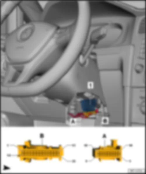
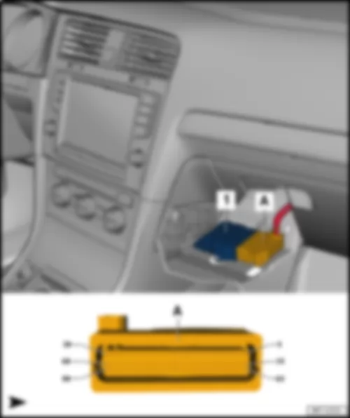
| 1 - | Parking aid control unit -J446- /park assist steering control unit -J791- | | A - | 26-pin connector -T26i- | | q | Connector assignment identical to LHD | | B - | 18-pin connector -T18k- | | q | Connector assignment identical to LHD |
| Emergency call module control unit and communication unit -J949- | | behind dash panel insert -KX2- | | | | | 1 - | Emergency call module control unit and communication unit -J949- | | A - | 26-pin connector -T26a- | | B - | 1) Emergency call module aerial -R263- |
| Connector assignment, data bus diagnostic interface -J533- | | | | | -T26a- (A) | Designation | | -T26a- (A) | Designation | | 1 | Terminal 30 | | 14 | B506 Connection (convenience CAN bus, high) in interior wiring harness | | 2 | B507 Connection (convenience CAN bus, low) in interior wiring harness | | 15 | | | 3 | | | 16 | | | 4 | Telephone microphone -R38- | | 17 | Telephone microphone -R38- | | 5 | Telephone microphone -R38- | | 18 | Telephone microphone -R38- | | 6 | Telematics button module -E734- | | 19 | Telematics button module -E734- | | 7 | Telematics button module -E734- | | 20 | Telematics button module -E734- | | 8 | | | 21 | | | 9 | | | 22 | | | 10 | Control unit 1 for information electronics -J794- | | 23 | | | 11 | Control unit 1 for information electronics -J794- | | 24 | | | 12 | | | 25 | | | 13 | | | 26 | Terminal 31 |
VW E-GOLF 2014 Data bus diagnostic interface J533Data bus diagnostic interface -J533- |
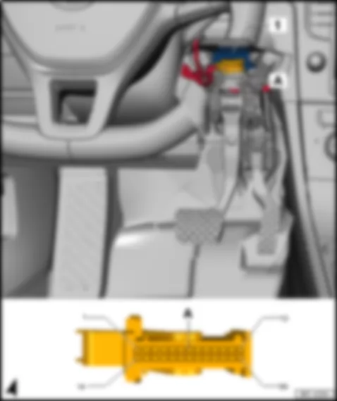
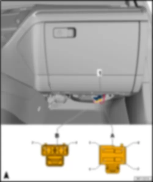
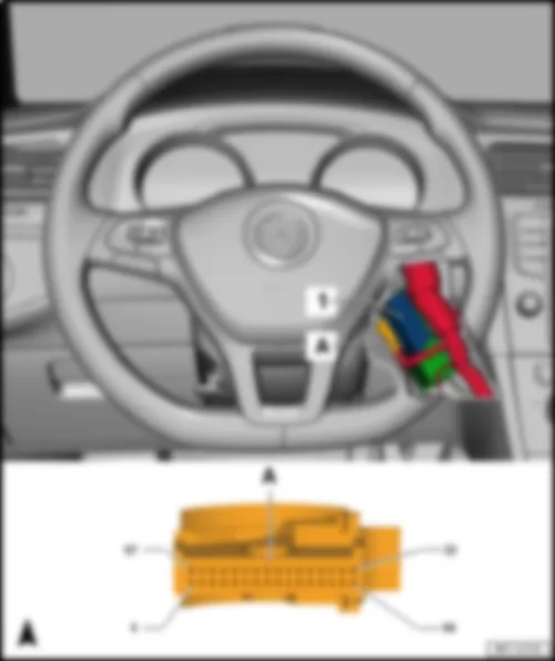
| | | | 1 - | Data bus diagnostic interface -J533- | | A - | 20-pin connector -T20- |
| Connector assignment, data bus diagnostic interface -J533- | | | | | -T20- (A) | Designation | | -T20- (A) | Designation | | 1 | Terminal 30 | | 11 | Terminal 31 | | 2 | Terminal 30 | | 12 | Terminal 31 | | 3 | A227 Connection 2 (LIN bus) in dash panel wiring harness | | 13 | B549 connection 2 (LIN bus) in main wiring harness | | 4 | | | 14 | Terminal 15 | | 5 | B407 Connection 2 (convenience CAN bus, low) in main wiring harness | | 15 | B398 Connection 2 (convenience CAN bus, high) in main wiring harness | | 6 | B390 Connection 1 (powertrain CAN bus, low) in main wiring harness | | 16 | B383 Connection 1 (powertrain CAN bus, high) in main wiring harness | | 7 | B109 Connection 1 (CAN bus extended, low) in main wiring harness | | 17 | B108 Connection 1 (CAN bus extended, high) in main wiring harness | | 8 | B664 Connection (running gear sensors CAN bus, low) in main wiring harness | | 18 | B663 Connection (running gear sensors CAN bus, high) in main wiring harness | | 9 | B714 Connection 1 (diagnostic CAN bus, low) in main wiring harness | | 19 | B713 Connection 1 (diagnostic CAN bus, high) in main wiring harness | | 10 | A179 Connection (infotainment CAN bus, low), in dash panel wiring harness | | 20 | A178 Connection (infotainment CAN bus, high), in dash panel wiring harness |
VW E-GOLF 2014 Airbag control unit J234Airbag control unit -J234- |
| | | | 1 - | Airbag control unit -J234- | | A - | 90-pin connector -T90- |
| Connector assignment of airbag control unit -J234- | | | | | -T90- (A) | Designation | | -T90- | Designation | | 1 | Key operated switch to deactivate front passenger side airbag -E224- | | 46 | | | 2 | | | 47 | Driver side knee airbag igniter -N295- | | 3 | Seat occupied sensor, front passenger side -G128- | | 48 | Driver side knee airbag igniter -N295- | | 4 | Front passenger airbag deactivated warning lamp -K145- | | 49 | Rear side airbag igniter on driver side -N201- | | 5 | Belt switch for seat row 2, passenger side -F392- | | 50 | Rear side airbag igniter on driver side -N201- | | 6 | Front passenger airbag deactivated warning lamp -K145- | | 51 | Rear belt tensioner igniter on driver side -N196- | | 7 | Belt switch for seat row 2, driver side -F390- | | 52 | Rear belt tensioner igniter on driver side -N196- | | 8 | | | 53 | Driver side curtain airbag igniter -N251- | | 9 | Belt switch for seat row 2, middle -F391- | | 54 | Driver side curtain airbag igniter -N251- | | 10 | | | 55 | Driver side airbag igniter -N95- | | 11 | | | 56 | Driver side airbag igniter -N95- | | 12 | | | 57 | Driver seat belt tensioner igniter 1 -N153- | | 13 | | | 58 | Driver seat belt tensioner igniter 1 -N153- | | 14 | | | 59 | Side airbag igniter on driver side -N199- | | 15 | | | 60 | Side airbag igniter on driver side -N199- | | 16 | | | 61 | Front passenger airbag deactivated warning lamp -K145- | | 17 | Battery regulation control unit -J840- | | 62 | B710 connection 5 (LIN bus) in main wiring harness | | 18 | Battery regulation control unit -J840- | | 63 | Driver side belt switch -E24-
Rear side airbag igniter on front passenger side -N202-
Rear side airbag igniter on driver side -N201-
Side airbag igniter on driver side -N199-
Side airbag igniter on front passenger side -N200-
Seat occupied sensor, front passenger side -G128-
Front passenger side belt switch -E25-
Belt switch for seat row 2, passenger side -F392-
Belt switch for seat row 2, driver side -F390-
Belt switch for seat row 2, middle -F391-
Front passenger side airbag igniter 1 -N131-
Key operated switch to deactivate front passenger side airbag -E224- | | 19 | Rear side airbag igniter on front passenger side -N202- | | 64 | | | 20 | Rear side airbag igniter on front passenger side -N202- | | 65 | | | 21 | Rear belt tensioner igniter on front passenger side -N197- | | 66 | | | 22 | Rear belt tensioner igniter on front passenger side -N197- | | 67 | | | 23 | Front passenger side curtain airbag igniter -N252- | | 68 | | | 24 | Front passenger side curtain airbag igniter -N252- | | 69 | | | 25 | Front passenger side airbag igniter 1 -N131- | | 70 | | | 26 | Front passenger side airbag igniter 1 -N131- | | 71 | | | 27 | Front passenger seat belt tensioner igniter 1 -N154- | | 72 | Crash sensor for front airbag -G190- | | 28 | Front passenger seat belt tensioner igniter 1 -N154- | | 73 | Crash sensor for front airbag -G190- | | 29 | Side airbag igniter on front passenger side -N200- | | 74 | | | 30 | Side airbag igniter on front passenger side -N200- | | 75 | | | 31 | Terminal 30 | | 76 | | | 32 | Key operated switch to deactivate front passenger side airbag -E224- | | 77 | | | 33 | Front passenger side belt switch -E25- | | 78 | | | 34 | | | 79 | | | 35 | Driver side belt switch -E24- | | 80 | Rear side airbag crash sensor on driver side -G256- | | 36 | | | 81 | Rear side airbag crash sensor on driver side -G256- | | 37 | | | 82 | Side airbag crash sensor on driver side -G179- | | 38 | | | 83 | Side airbag crash sensor on driver side -G179- | | 39 | Diagnostic connection -U31- | | 84 | Rear side airbag crash sensor on front passenger side -G257- | | 40 | | | 85 | Rear side airbag crash sensor on front passenger side -G257- | | 41 | | | 86 | Side airbag crash sensor on front passenger side -G180- | | 42 | | | 87 | Side airbag crash sensor on front passenger side -G180- | | 43 | | | 88 | | | 44 | | | 89 | B383 Connection 1 (powertrain CAN bus, high) in main wiring harness | | 45 | | | 90 | B390 Connection 1 (powertrain CAN bus, low) in main wiring harness |
VW E-GOLF 2014 Control unit for cornering light and headlight range control J745Control unit for cornering light and headlight range control -J745- |
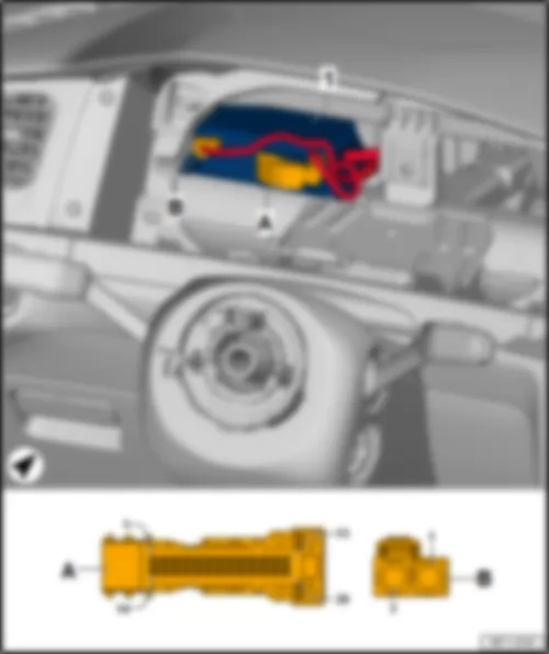
| Behind dash panel on driver side. | | | | | 1 - | Control unit for cornering light and headlight range control -J745- | | A - | 26-pin connector -T26h- |
| Connector assignment of control unit for cornering light and headlight range control -J745- | | | | | -T26h- (A) | Designation | | -T26h- (A) | Designation | | 1 | | | 14 | | | 2 | B668 Connection 2 (CAN bus extended, high) in main wiring harness | | 15 | Right headlight range control motor -V49- | | 3 | B669 Connection 2 (CAN bus extended, low) in main wiring harness | | 16 | Left headlight range control motor -V48- | | 4 | | | 17 | Left headlight range control motor -V48- | | 5 | | | 18 | Left headlight range control motor -V48- | | 6 | | | 19 | Left headlight range control motor -V48- | | 7 | | | 20 | Right headlight range control motor -V49- | | 8 | | | 21 | Right headlight range control motor -V49- | | 9 | | | 22 | Right headlight range control motor -V49- | | 10 | | | 23 | Terminal 15 | | 11 | | | 24 | Terminal 31 | | 12 | | | 25 | | | 13 | | | 26 | |
VW E-GOLF 2014 Module monitor control unit for batteries J497Module monitor control unit for batteries -J497- |
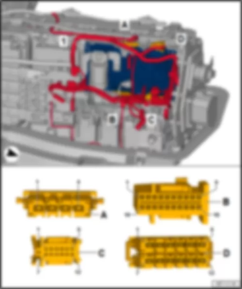
| in high-voltage battery 1 -AX2- | | | | | 1 - | Module monitor control unit for batteries -J497- | | A - | 4-pin connector -T4bx- | | B - | 18-pin connector -T18c- | | C - | 12-pin connector -T12j- | | D - | 12-pin connector -T12i- |
| Connector assignment of module monitor control unit for batteries -J497- | | | | | -T4bx- (A) | Designation | | -T18c- (B) | Designation | | -T12j- (C) | Designation | | -T12i- (D) | Designation | | 1 | Terminal 31 | | 1 | Terminal 30 | | 1 | Precharge contactor for high-voltage battery -J1044- | | 1 (1A) | High-voltage battery power contactor 2 -J1058- | | 2 | | | 2 | Terminal 30 | | 2 | High-voltage battery power contactor 1 -J1057- | | 2 (2A) | High-voltage battery power contactor 2 -J1058- | | 3 | | | 3 | | | 3 | High-voltage battery power contactor 2 -J1058- | | 3 (3A) | Protection resistor for high-voltage battery -N662-
Precharge contactor for high-voltage battery -J1044- | | 4 | | | 4 | Battery regulation control unit -J840- | | 4 | DC charge contactor 1 -J1052- | | 4 (4A) | Protection resistor for high-voltage battery -N662-
High-voltage battery power contactor 1 -J1057- | | | | | 5 | | | 5 | DC charge contactor 2 -J1053- | | 5 (5A) | Current sensor for high-voltage battery -G848- | | | | | 6 | Terminal 31 | | 6 | | | 6 (6A) | High-voltage system fuse 1 -S350- | | | | | 7 | | | 7 | Precharge contactor for high-voltage battery -J1044- | | 7 (1B) | Precharge contactor for high-voltage battery -J1044-
High-voltage battery power contactor 1 -J1057- | | | | | 8 | Terminal 31 | | 8 | High-voltage battery power contactor 1 -J1057- | | 8 (2B) | DC charge contactor 2 -J1053- | | | | | 9 | Terminal 31 | | 9 | High-voltage battery power contactor 2 -J1058- | | 9 (3B) | High-voltage system fuse 1 -S350- | | | | | 10 | Terminal 30 | | 10 | DC charge contactor 1 -J1052- | | 10 (4B) | DC charge contactor 1 -J1052- | | | | | 11 | | | 11 | | | 11 (5B) | Current sensor for high-voltage battery -G848- | | | | | 12 | | | 12 | DC charge contactor 2 -J1053- | | 12 (6B) | High-voltage battery power contactor 2 -J1058- | | | | | 13 | X5 Connection 1 (hybrid CAN bus, low) in engine compartment wiring harness | | | | | | | | | | | 14 | X4 Connection 1 (hybrid CAN bus, high) in engine compartment wiring harness | | | | | | | | | | | 15 | | | | | | | | | | | | 16 | Terminal 30 | | | | | | | | | | | 17 | | | | | | | | | | | | 18 | Terminal 31 | | | | | | |
VW E-GOLF 2014 Battery regulation control unit J840Battery regulation control unit -J840- |
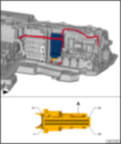
| in high-voltage battery 1 -AX2- | | | | | 1 - | Battery regulation control unit -J840- | | A - | 32-pin connector -T32j- |
| Connector assignment of battery regulation control unit -J840- | | | | | -T32j- (A) | Designation | | -T32j– (A) | Designation | | 1 | X4 Connection 1 (hybrid CAN bus, high) in engine compartment wiring harness | | 17 | Terminal 30 | | 2 | X5 Connection 1 (hybrid CAN bus, low) in engine compartment wiring harness | | 18 | E125 Connection 2 (powertrain CAN bus, high) in engine wiring harness | | 3 | B384 Connection 2 (powertrain CAN bus, high) in main wiring harness | | 19 | E126 Connection 2 (powertrain CAN bus, low) in engine wiring harness | | 4 | B391 Connection 2 (powertrain CAN bus, low) in main wiring harness | | 20 | Module monitor control unit for batteries -J497- | | 5 | Charging unit 1 for high-voltage battery -AX4- | t | Maintenance connector for high-voltage system -TW- | | | 21 | Pilot line | | 6 | | | 22 | | | 7 | | | 23 | | | 8 | | | 24 | | | 9 | | | 25 | | | 10 | Battery module 0 -J1068- | | 26 | | | 11 | | | 27 | | | 12 | Battery module 0 -J1068- | | 28 | Battery module 25 -J1084- | | 13 | Airbag control unit -J234- | | 29 | Airbag control unit -J234- | | 14 | Terminal 30 | | 30 | Terminal 31 | | 15 | | | 31 | | | 16 | Terminal 31 | | 32 | Terminal 30 |
VW E-GOLF 2014 Fresh air blower control unit J126Fresh air blower control unit -J126- |
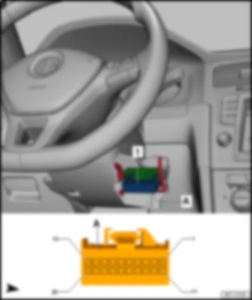
| On heater and air conditioner unit, front passenger footwell. | | | | | 1 - | Fresh air blower control unit -J126- | | A - | 4-pin connector -T4dc- | | B - | 2-pin connector -T2dq- |
| Connector assignment, fresh air blower control unit -J126- | | | | | -T4dc- (A) | Designation | | -T2dq- (B) | Designation | | 1 | Terminal 31 | | 1 | Fresh air blower -V2- | | 2 | | | 2 | Fresh air blower -V2- | | 3 | Terminal 30 | | | | | 4 | A209 Connection 1 (LIN bus) in dash panel wiring harness | | | |
VW E-GOLF 2014 Interface for entry and start system J965 | Interface for entry and start system -J965- | | Interface for entry and start system -J965- , left-hand drive models | | |
| 1 - | Interface for entry and start system -J965- | | A - | 32-pin connector -T32b- |
| Connector assignment of interface for entry and start system -J965- , left-hand drive models | | | | | -T32b- (A) | Designation | | -T32b– (A) | Designation | | 1 | | | 17 | Terminal 31 | | 2 | | | 18 | | | 3 | Terminal 30 | | 19 | Interior aerial 1 for entry and start system -R138- | | 4 | | | 20 | Rear bumper aerial for entry and start system -R136- | | 5 | Front passenger door exterior handle contact sensor -G416- | | 21 | Passenger side aerial for entry and start system -R135- | | 6 | | | 22 | Luggage compartment aerial for entry and start system -R137- | | 7 | | | 23 | Driver side aerial for entry and start system -R134- | | 8 | | | 24 | Driver side aerial for entry and start system -R134- | | 9 | Driver door exterior handle contact sensor -G415- | | 25 | Luggage compartment aerial for entry and start system -R137- | | 10 | Onboard supply control unit -J519- | | 26 | Passenger side aerial for entry and start system -R135- | | 11 | | | 27 | Rear bumper aerial for entry and start system -R136- | | 12 | | | 28 | Interior aerial 1 for entry and start system -R138- | | 13 | | | 29 | | | 14 | | | 30 | Ignition and starter button illumination bulb -L190- | | 15 | | | 31 | | | 16 | B407 Connection 2 (convenience CAN bus, low) in main wiring harness | | 32 | B398 Connection 2 (convenience CAN bus, high) in main wiring harness |
| 1 - | Interface for entry and start system -J965- | | A - | 32-pin connector -T32b- | | q | Connector assignment identical to LHD |
| | | | |

