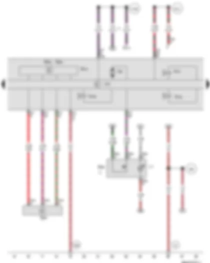
Wiring Diagram VW NEW SAGITAR 2014 - Rear right speed sensor - Front right speed sensor - Rear left speed sensor - Front left speed sensor - ABS control unit

| G44 | Rear right speed sensor |
| G45 | Front right speed sensor |
| G46 | Rear left speed sensor |
| G47 | Front left speed sensor |
| J104 | ABS control unit |
| N133 | Rear right ABS inlet valve |
| N134 | Rear left ABS inlet valve |
| SB16 | Fuse 16 on fuse holder B |
| SB23 | Fuse 23 on fuse holder B |
| T2ar | 2-pin connector |
| T2as | 2-pin connector |
| T2at | 2-pin connector |
| T2au | 2-pin connector |
| T47 | 47-pin connector |
| D146 | Connection (rear left speed sensor +), in engine compartment wiring harness |
| D147 | Connection (rear left speed sensor -), in engine compartment wiring harness |
| D148 | Connection (rear right speed sensor +), in engine compartment wiring harness |
| D149 | Connection (rear right speed sensor -), in engine compartment wiring harness |
| D184 | Connection (front left speed sensor +), in engine compartment wiring harness |
| D185 | Connection (front left speed sensor -), in engine compartment wiring harness |
| * | Cross section depends on equipment |
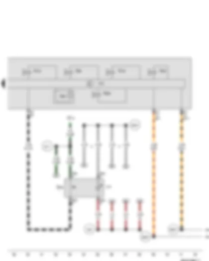
Wiring Diagram VW NEW SAGITAR 2014 - Vacuum sender - ABS control unit
| E256 | TCS and ESP button |
| F | Brake light switch |
| G200 | Lateral acceleration sender |
| G202 | Yaw rate sender |
| G419 | ESP sensor unit |
| G608 | Vacuum sender |
| J104 | ABS control unit |
| L71 | Traction control switch illumination bulb |
| N101 | Front left ABS inlet valve |
| N135 | Rear right ABS outlet valve |
| N136 | Rear left ABS outlet valve |
| SC14 | Fuse 14 on fuse holder C |
| T4al | 4-pin connector |
| T4bn | 4-pin connector |
| T6au | 6-pin connector |
| T47 | 47-pin connector |
| V64 | ABS hydraulic pump |
| 43 | Earth point, lower part of right A-pillar |
| 366 | Earth connection 1, in main wiring harness |
| 638 | Earth point, on right A-pillar |
| A199 | Positive connection 4 (15a) in dash panel wiring harness |
| B131 | Connection (54), in interior wiring harness |
| * | Only models with hydraulic brake servo (HBS) |
| *2 | Only models with electronic stabilisation program (ESP) |
| *3 | Only models with "High" equipment (AW1) |
Wiring Diagram VW NEW SAGITAR 2014 - Tyre Pressure Loss Indicator button - ABS control unit
| E492 | Tyre Pressure Loss Indicator button |
| G201 | Brake pressure sender 1 |
| J104 | ABS control unit |
| L76 | Button illumination bulb |
| N99 | Front right ABS inlet valve |
| N100 | Front right ABS outlet valve |
| N102 | Front left ABS outlet valve |
| N227 | Vehicle stabilization program high-pressure valve 1 |
| N228 | Vehicle stabilization program high-pressure valve 2 |
| SC13 | Fuse 13 on fuse holder C |
| T6ak | 6-pin connector |
| T47 | 47-pin connector |
| 388 | Earth connection 23, in main wiring harness |
| A217 | Positive connection 8 (15a) in dash panel wiring harness |
| B340 | Connection 1 (58d), in main wiring harness |
| B383 | Connection 1 (powertrain CAN bus, high), in main wiring harness |
| B390 | Connection 1 (powertrain CAN bus, low), in main wiring harness |
| * | Only models with Tyre Pressure Monitoring System |
| *2 | Only models with "High" equipment (AW1) |
| *3 | Only models with "Low" equipment (AW0) |
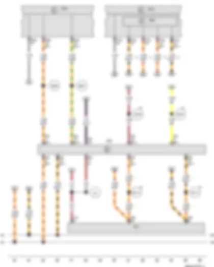
Wiring Diagram VW NEW SAGITAR 2014 - Onboard supply control unit - Data bus diagnostic interface
| J519 | Onboard supply control unit |
| J533 | Data bus diagnostic interface, in left footwell, near centre console |
| T16 | 16-pin connector |
| T20 | 20-pin connector |
| T52b | 52-pin connector |
| T52c | 52-pin connector |
| T73b | 73-pin connector |
| U31 | Diagnostic connection |
| 80 | Earth connection 1, in dash panel wiring harness |
| B383 | Connection 1 (powertrain CAN bus, high), in main wiring harness |
| B390 | Connection 1 (powertrain CAN bus, low), in main wiring harness |
| B397 | Connection 1 (convenience CAN bus, high), in main wiring harness |
| B406 | Connection 1 (convenience CAN bus, low), in main wiring harness |
| B708 | Connection 1 (dash panel insert CAN bus high) in main wiring harness |
| B709 | Connection 1 (dash panel insert CAN bus low) in main wiring harness |
| B713 | Connection 1 (CAN bus diagnosis, high), in main wiring harness |
| B714 | Connection 1 (CAN bus diagnosis, low), in main wiring harness |
| * | Only models with "High" equipment (AW1) |
| *2 | From July 2013 |
| *3 | Only models with "Low" equipment (AW0) |
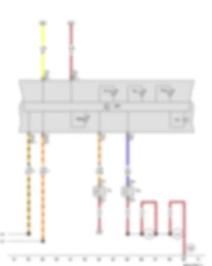
Wiring Diagram VW NEW SAGITAR 2014 - Handbrake warning switch - Brake fluid level warning contact - Control unit in dash panel insert
| F9 | Handbrake warning switch |
| F34 | Brake fluid level warning contact |
| H3 | Buzzer and gong |
| J285 | Control unit in dash panel insert |
| K47 | ABS warning lamp |
| K118 | Brake system warning lamp |
| K155 | ESP and TCS warning lamp |
| K220 | Tyre Pressure Loss Indicator warning lamp |
| T2ap | 2-pin connector |
| T2w | 2-pin connector |
| T16 | 16-pin connector |
| T32 | 32-pin connector |
| 132 | Earth connection 3, in engine compartment wiring harness |
| 376 | Earth connection 11, in main wiring harness |
| 655 | Earth point, on left headlight |
| B383 | Connection 1 (powertrain CAN bus, high), in main wiring harness |
| B390 | Connection 1 (powertrain CAN bus, low), in main wiring harness |
| * | Cross section depends on equipment |
| *2 | Only models with "Low" equipment (AW0) |
Can't find your car? Check -> DiagnostData.com!


