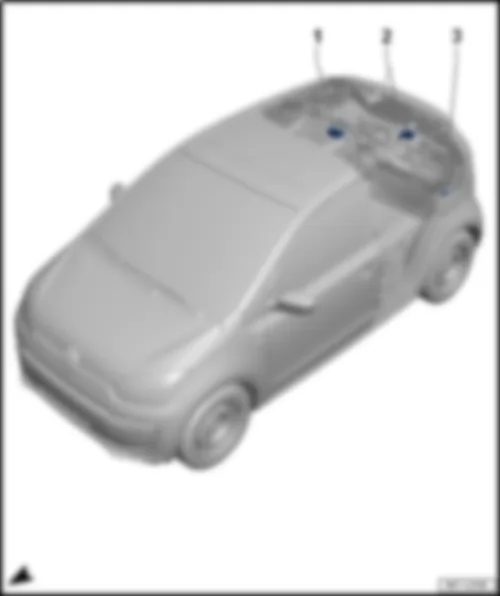
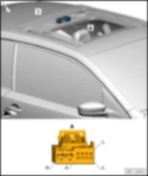
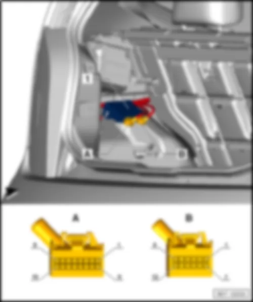
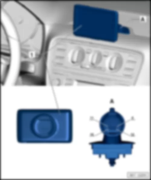
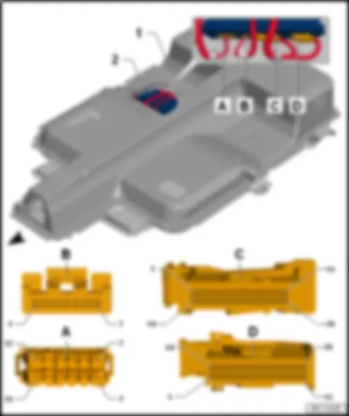
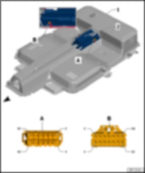
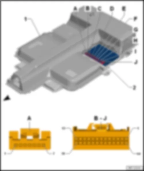
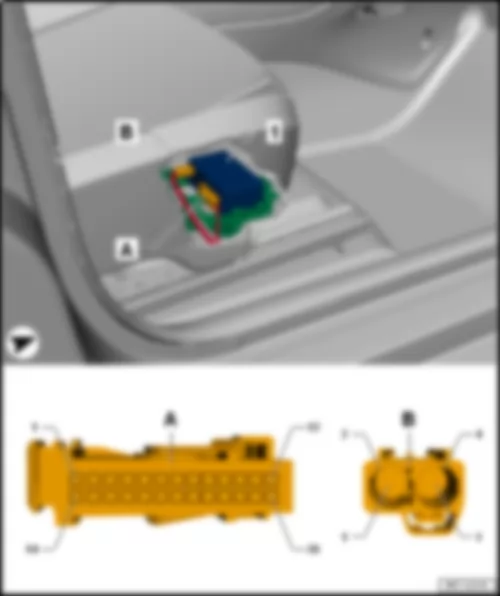
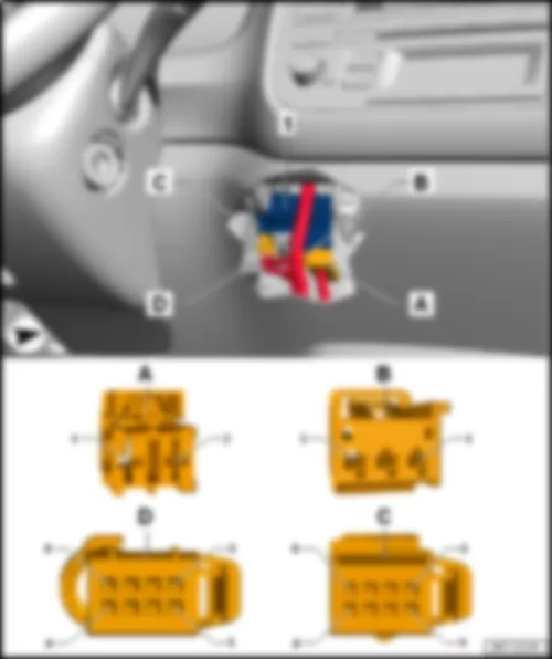
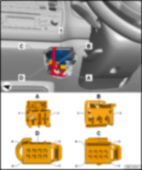
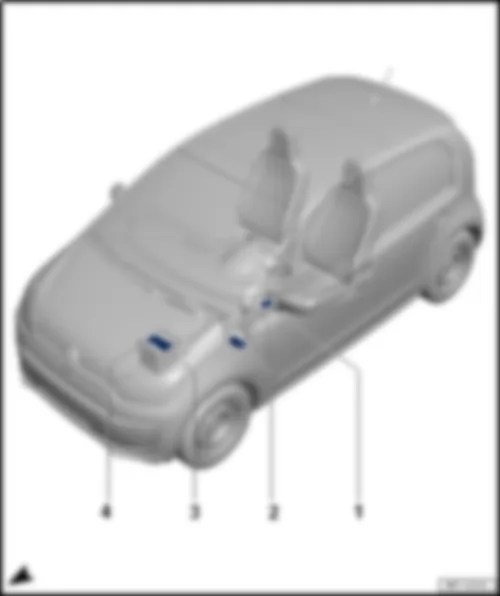
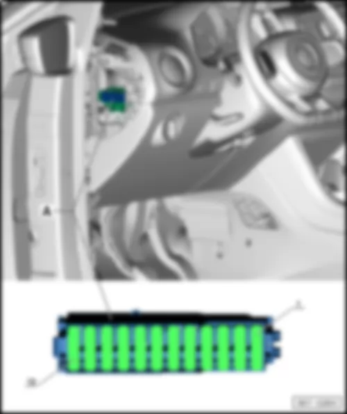
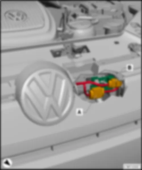
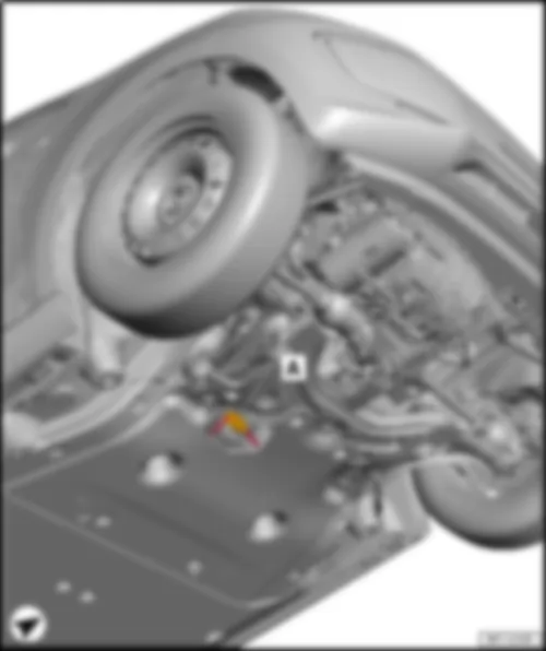
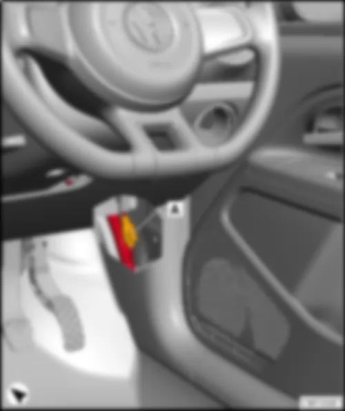
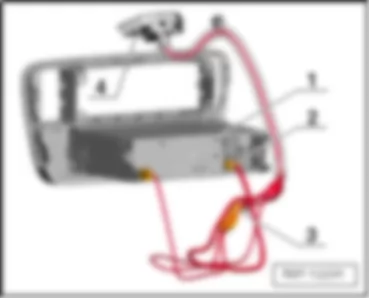
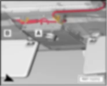
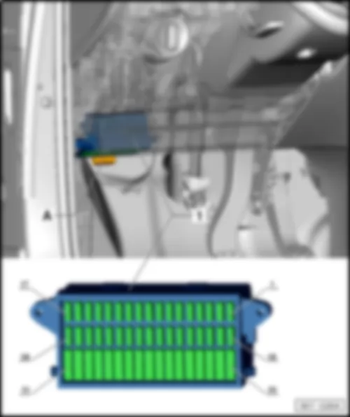
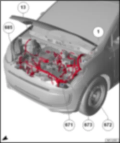
| 1 - | Onboard supply control unit -J519- | | A - | 73-pin connector -T73a- , black | | B - | 73-pin connector -T73b- , white |
| Onboard supply control unit -J519- | | Connector assignment of onboard supply control unit -J519- | | | | | -T73a- (A) | Designation | | -T73b- (B) | Designation | | | 1 | | | 1 | | | | 2 | Left dipped beam | | 2 | Right dipped beam | | | 3 | | | 3 | Left daytime running lights | | | 4 | Interior light dimmer | | 4 | 58D supply | | | 5 | Right daytime running lights | | 5 | Left tail light | | | 6 | Rear fog light | | 6 | Right tail light | | | 7 | | | 7 | Number plate light | | | 8 | | | 8 | | | | 9 | Emergency braking function button | | 9 | | | | 10 | Central locking authorisation motor, rear lid | | 10 | | | | 11 | Central locking, lock motor, driver | | 11 | Terminal 30 reversing light, dipped beam headlight | | | 12 | Central locking, common motor, driver | | 12 | Reversing light | | | 13 | Central locking, safe, driver | | 13 | Terminal 30 left turn signal/brake light | | | 14 | Terminal 31 central locking | | 14 | Left turn signal | | | 15 | Central locking motor front passenger | | 15 | Right turn signal | | | 16 | Terminal 30 central locking | | 16 | Brake light | | | 17 | Central locking status rear left door lock | | 17 | | | | 18 | Central locking status rear right door lock | | 18 | Powertrain CAN bus low | | | 19 | Driver door rotary latch | | 19 | Powertrain CAN bus high | | | 20 | Passenger door rotary latch | | 20 | Convenience CAN bus high | | | 21 | Central locking status lock, front passenger | | 21 | Convenience CAN bus low | | | 22 | Central locking status lock, driver | | 22 | Diagnosis CAN bus low | | | 23 | Unlock rear lid | | 23 | Diagnosis CAN bus high | | | 24 | Central locking lock position, driver | | 24 | LIN 2, roof | | | 25 | Central locking unlock button | | 25 | | | | 26 | Rear right rotary latch | | 26 | | | | 27 | Bonnet contact | | 27 | Front wipers 1st stage, steering column lock switch | | | 28 | Hazard warning button | | 28 | | | | 29 | Horn button | | 29 | Rotary light switch - zero position | | | 30 | Rear lid main latch | | 30 | | | | 31 | Rear lid first latch | | 31 | Heated rear window button | | | 32 | Right turn signal, steering column switch | | 32 | Front wiper, end switch | | | 33 | Left turn signal, steering column switch | | 33 | Windscreen heater button | | | 34 | Rear left rotary latch | | 34 | | | | 35 | | | 35 | | | | 36 | Seat heating authorisation | | 36 | | | | 37 | | | 37 | LIN, alternator | | | 38 | Heated exterior mirror | | 38 | Terminal 31 electronics | | | 39 | | | 39 | Terminal 30 electronics | | | 40 | Right side light | | 40 | | | | 41 | Left side light | | 41 | | | | 42 | Terminal S ignition/starter switch | | 42 | | | | 43 | Brake light sensor | | 43 | Rear fog light, rotary light switch | | | 44 | Terminal 15 ignition/starter switch | | 44 | CCS set, steering column switch | | | 45 | Side light, rotary light switch | | 45 | CCS E/A, steering column switch | | | 46 | | | 46 | CCS RES, steering column switch | | | 47 | | | 47 | CCS cancel, steering column switch | | | 48 | | | 48 | | | | 49 | | | 49 | | | | 50 | Windscreen heater relay | | 50 | Terminal 50 ignition/starter switch | | | 51 | | | 51 | | | | 52 | | | 52 | Dip beam position, rotary light switch | | | 53 | | | 53 | Front wipers 2nd stage, steering column lock switch | | | 54 | Terminal X relay | | 54 | Dash panel CAN bus high | | | 55 | | | 55 | | | | 56 | Hazard warning light button LED | | 56 | | | | 57 | | | 57 | Dash panel CAN bus low | | | 58 | LED Safe LED | | 58 | Heated exterior mirror switch | | | 59 | | | 59 | Terminal 30 reference | | | 60 | Heated rear window LED | | 60 | Terminal 31 reference | | | 61 | Windscreen heater LED | | 61 | Steering column switch, washer pump | | | 62 | Main beam, steering column switch | | 62 | Steering column switch, front wiper intermittent | | | 63 | Terminal 30 left dipped beam/daytime running lights/main beam | | 63 | Heated rear window | | | 64 | Terminal 30 exterior mirror heating | | 64 | | | | 65 | Terminal 30G | | 65 | | | | 66 | Terminal 30 interior light / 30G | | 66 | | | | 67 | | | 67 | Terminal 30 heated rear window | | | 68 | Terminal 30 windscreen wiper | | 68 | Terminal 30 right dipped beam/daytime running lights/main beam | | | 69 | Front wipers 1st stage | | 69 | | | | 70 | Brake earth, front wiper | | 70 | | | | 71 | Front wipers 2nd stage | | 71 | | | | 72 | Horn | | 72 | | | | 73 | Terminal 30 horn | | 73 | | |
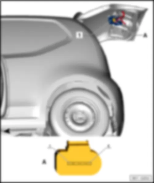
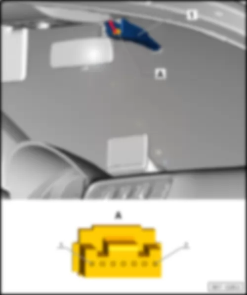
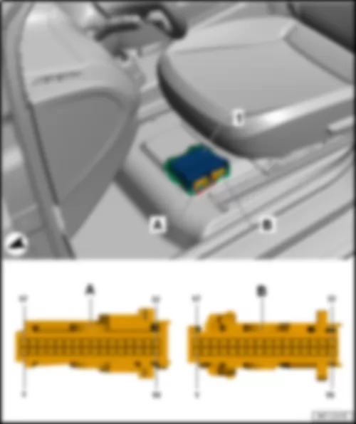
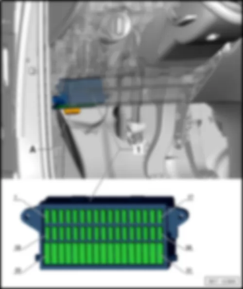
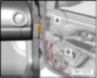
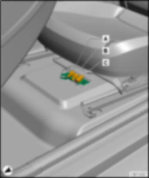
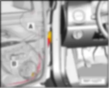
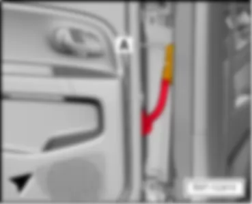
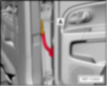
| Emergency call module control unit and communication unit -J949- | | under seat on front right | | | | | 1 - | Emergency call module control unit and communication unit -J949- | | A - | 26-pin connector -T26a- | | B - | 4-pin connector -T4ac- |
| Connector assignment of emergency call module control unit and communication unit -J949- | | | | | -T26a- (A) | Designation | | -T26a- (A) | Designation | | -T4ac- (B) | Designation | | | 1 | Terminal 30 | | 14 | Convenience CAN bus high | | 1 | GSM aerial -R205- | | | 2 | Convenience CAN bus low | | 15 | | | 2 | GSM aerial -R205- , shield | | | 3 | | | 16 | | | 3 | GPS aerial -R50- | | | 4 | | | 17 | | | 4 | GPS aerial -R50- , shield | | | 5 | | | 18 | | | | | | | 6 | | | 19 | | | | | | | 7 | | | 20 | | | | | | | 8 | | | 21 | | | | | | | 9 | | | 22 | | | | | | | 10 | | | 23 | | | | | | | 11 | | | 24 | | | | | | | 12 | | | 25 | | | | | | | 13 | | | 26 | Terminal 31 | | | | |
VW E-UP 2016 Heated front seats control unit -J774- , left-hand drive models |
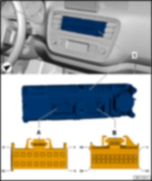
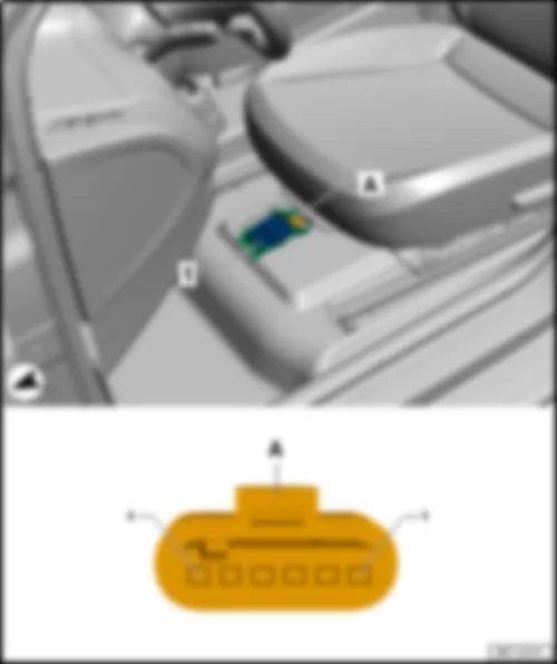
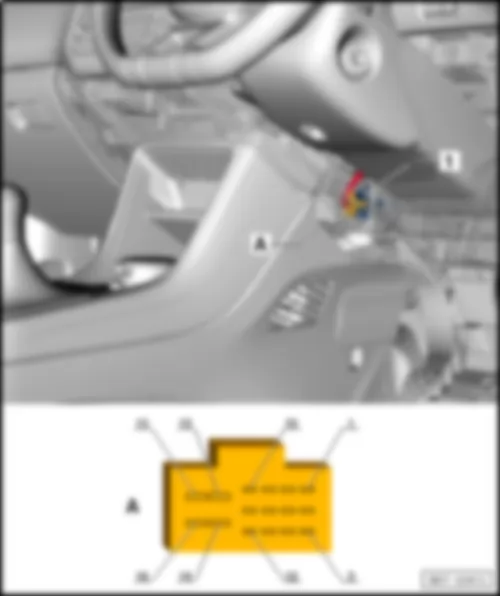
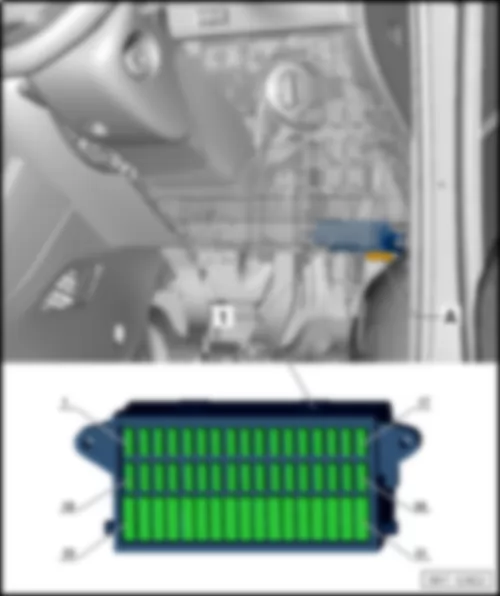
| behind centre console, left | | | | | 1 - | Heated front seats control unit -J774- | | A - | 16-pin connector -T16a- |
| Connector assignment of heated front seats control unit -J774- | | | | | -T16a- (A) | Designation | | | 1 | Centre switch module 2 in dash panel -EX35- , LED, stage 1, right | | | 2 | Switch module in centre of dash panel -EX22- , LED, stage 2, left | | | 3 | Centre switch module 2 in dash panel -EX35- , LED, stage 2, right | | | 4 | Switch module in centre of dash panel -EX22- , LED, stage 1, left | | | 5 | Onboard supply control unit -J519- , authorisation | | | 6 | Switch module in centre of dash panel -EX22- | | | 7 | | | | 8 | | | | 9 | Terminal 31 | | | 10 | -- | | | 11 | -- | | | 12 | Centre switch module 2 in dash panel -EX35- | | | 13 | Terminal 75 | | | 14 | Terminal 75 | | | 15 | Seat heating left | | | 16 | Seat heating left | |
VW E-UP 2016 Heated front seats control unit -J774- , right-hand drive models |
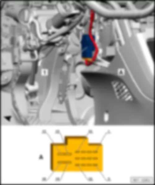
| behind centre console, right | | | | | 1 - | Heated front seats control unit -J774- | | A - | 16-pin connector -T16a- |
| Connector assignment of heated front seats control unit -J774- | | | | | -T16a- (A) | Designation | | | 1 | Centre switch module 2 in dash panel -EX35- , LED, stage 1, right | | | 2 | Switch module in centre of dash panel -EX22- , LED, stage 2, left | | | 3 | Centre switch module 2 in dash panel -EX35- , LED, stage 2, right | | | 4 | Switch module in centre of dash panel -EX22- , LED, stage 1, left | | | 5 | Onboard supply control unit -J519- , authorisation | | | 6 | Switch module in centre of dash panel -EX22- | | | 7 | | | | 8 | | | | 9 | Terminal 31 | | | 10 | -- | | | 11 | -- | | | 12 | Centre switch module 2 in dash panel -EX35- | | | 13 | Terminal 75 | | | 14 | Terminal 75 | | | 15 | Seat heating left | | | 16 | Seat heating left | |
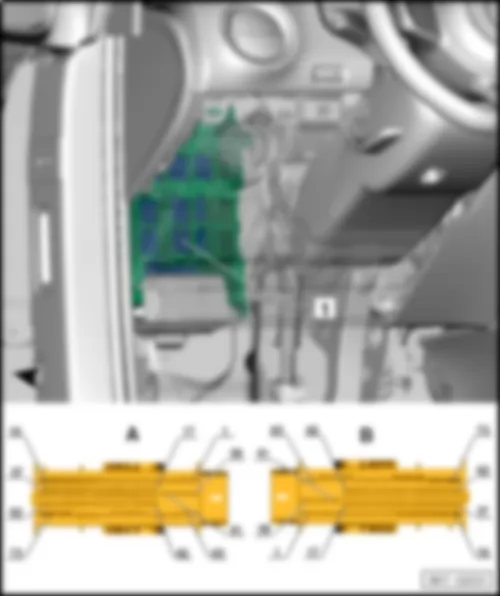
VW E-UP 2016 Airbag control unit J234Airbag control unit -J234- |
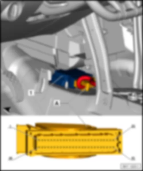
| | | | 1 - | Airbag control unit -J234- | | A - | 50-pin connector -T50- |
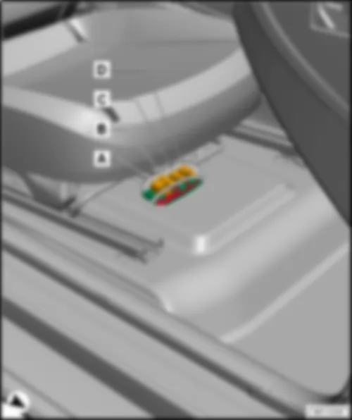
VW E-UP 2016 Power steering control unit -J500- , left-hand drive models |
| | | | 1 - | Power steering control unit -J500- | | A - | 2-pin connector -T2aq- | | B - | 3-pin connector -T3p- | | C - | 8-pin connector -T8i- | | D - | 8-pin connector -T8j- |
| Connector assignment of power steering control unit -J500- | | | | | -T2aq- (A) | Designation | | -T3p- (B) | Designation | | | 1 | Terminal 31 | | 1 | Powertrain CAN bus low | | | 2 | Terminal 30 | | 2 | Powertrain CAN bus high | | | | | | 3 | Terminal 15 | |
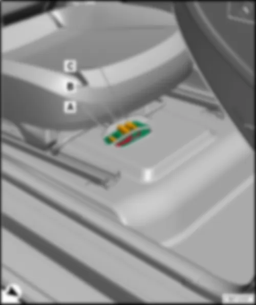
VW E-UP 2016 Power steering control unit -J500- , right-hand drive models |
| | | | 1 - | Power steering control unit -J500- | | A - | 2-pin connector -T2aq- | | B - | 3-pin connector -T3p- | | C - | 8-pin connector -T8i- | | D - | 8-pin connector -T8j- |
| Connector assignment of power steering control unit -J500- | | | | | -T2aq- (A) | Designation | | -T3p- (B) | Designation | | | 1 | Terminal 31 | | 1 | Powertrain CAN bus low | | | 2 | Terminal 30 | | 2 | Powertrain CAN bus high | | | | | | 3 | Terminal 15 | |
VW E-UP 2016 Fresh air blower control unit J126Fresh air blower control unit -J126- |
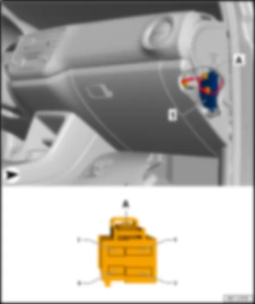
| On heater and air conditioner unit, front passenger footwell. | | | | | 1 - | Fresh air blower control unit -J126- | | A - | 4-pin connector -T4aa- , black |
| Connector assignment of fresh air blower control unit -J126- | | | | | -T4aa- (A) | Designation | | | 1 | Terminal 31 | | | 2 | | | | 3 | Terminal 30 | | | 4 | LIN bus | |
VW E-UP 2016 Overview of fuses | Overview of fuses | Note | The fitting locations are identical on LHD and RHD models. | | | |
| No. | | Current Flow Diagram designation | Nominal value | Function/component | Terminal |
| 1 | - | Fuse 1 on fuse holder C -SC1- | 7.5A | Dash panel insert -K-
Engine control unit -J623- | 15 |
| 2 | - | Fuse 2 on fuse holder C -SC2- | 7.5A | High-voltage battery 1 -AX2-Diagnostic connection -U31- | 15 |
| 3 | - | Not assigned | - | | - |
| 4 | - | Not assigned | - | | - |
| 5 | - | Fuse 5 on fuse holder C -SC5- | 7.5A | Steering column combination switch -E595-
Onboard supply control unit -J519- | 15 |
| 6 | - | Fuse 6 on fuse holder C -SC6- | 7.5A | Mirror adjustment switch -E43-
Headlight range control regulator -E102-
Left headlight range control motor -V48-
Right headlight range control motor -V49- | 15 |
| 7 | - | Fuse 7 on fuse holder C -SC7- | 10A | Power and control electronics for electric drive -JX1- | 30 |
| 8 | - | Fuse 8 on fuse holder C -SC8- | 7.5A | Selector lever -E313-
Brake servo control unit -J539-
Charge voltage control unit for high-voltage battery -J966-
Power and control electronics for electric drive -JX1- | 15 |
| 9 | - | Fuse 9 on fuse holder C -SC9- | 7.5A | Centre switch module 2 in dash panel -EX35-
Airbag control unit -J234- | 15 |
| 10 | - | Fuse 10 on fuse holder C -SC10- | 7.5A | Parking aid control unit -J446- | 15 |
| 11 | - | Not assigned | - | | - |
| 12 | - | Fuse 12 on fuse holder C -SC12- | 7.5A | Light switch -E1- | 75 |
| 13 | - | Not assigned | - | | - |
| 14 | - | Fuse 14 on fuse holder C -SC14- | 15A | Rear window wiper motor -V12- | 75 |
| 15 | - | Fuse 15 on fuse holder C -SC15- | 15A | Light switch -E1- | 30 |
| 16 | - | Fuse 16 on fuse holder C -SC16- | 7.5A | Terminal 15 voltage supply relay -J329-
Power steering control unit -J500- | 15 |
| 17 | - | Fuse 17 on fuse holder C -SC17- | 15A | Steering column combination switch -E595- | 15 |
| 18 | - | Fuse 18 on fuse holder C -SC18- | 15A | Charging unit 1 for high-voltage battery -AX4- | 30 |
| 19 | - | Not assigned | - | | - |
| 20 | - | Fuse 20 on fuse holder C -SC20- | 7.5A | ABS control unit -J104-
Emergency braking function sensor unit -J939- | 15 |
| 21 | - | Not assigned | - | | - |
| 22 | - | Not assigned | - | | - |
| 23 | - | Fuse 23 on fuse holder C -SC23- | 7.5A | Engine control unit -J623- | 30 |
| 24 | - | Fuse 24 on fuse holder C -SC24- | 15A | Steering column combination switch -E595- | t | Headlight flasher switch -E5- | | 30 |
| 25 | - | Fuse 25 on fuse holder C -SC25- | 10A | Windscreen and rear window washer pump -V59- | 53c |
| 26 | - | Fuse 26 on fuse holder C -SC26- | 7.5A | Main relay -J271-
Dash panel insert -K- | 30 |
| 27 | - | Fuse 27 on fuse holder C -SC27- | 7.5A | Onboard supply control unit -J519- | t | Front interior light -W1- | | t | Front passenger reading light -W13- | | t | Driver side reading light -W19- | | 30 |
| 28 | - | Fuse 28 on fuse holder C -SC28- | 7.5A | Diagnostic connection -U31- | 30 |
| 29 | - | Fuse 29 on fuse holder C -SC29- | 7.5A | Onboard supply control unit -J519- | 30 |
| 30 | - | Fuse 30 on fuse holder C -SC30- | 7.5A | Onboard supply control unit -J519- | t | Heated exterior mirror on driver side -Z4- | | t | Heated exterior mirror on front passenger side -Z5- | | 30 |
| 31 | - | Fuse 31 on fuse holder C -SC31- | 10A | Radiator fan -V7- | 87 |
| 32 | - | Fuse 32 on fuse holder C -SC32- | 15A | Onboard supply control unit -J519- | t | Turn signal/brake light | | 30 |
| 33 | - | Fuse 33 on fuse holder C -SC33- | 10A | Front right headlight -MX2- | t | Right headlight main beam bulb -M32- | | 56a |
| 34 | - | Fuse 34 on fuse holder C -SC34- | 10A | Dash panel insert -K-
Onboard supply control unit -J519-
Front left headlight -MX1- | t | Left headlight main beam bulb -M30- | | 56a |
| 35 | - | Not assigned | - | | - |
| 36 | - | Fuse 36 on fuse holder C -SC36- | 30A | Cigarette lighter -U1- | 75 |
| 37 | - | Not assigned | - | | - |
| 38 | - | Fuse 38 on fuse holder C -SC38- | 15A | Radio -R- | 30 |
| 39 | - | Fuse 39 on fuse holder C -SC39- | 30A | Sliding sunroof adjustment control unit -J245- | 30 |
| 40 | - | Fuse 40 on fuse holder C -SC40- | 15A | Engine control unit -J623- | 87 |
| 41 | - | Fuse 41 on fuse holder C -SC41- | 25A | Onboard supply control unit -J519- | 30 |
| 42 | - | Fuse 42 on fuse holder C -SC42- | 20A | High-temperature circuit coolant pump -V467-
Coolant circulation pump before power and control electronics for electric drive -V508- | 87 |
| 43 | - | Fuse 43 on fuse holder C -SC43- | 20A | Switch module in centre of dash panel -EX22-
Centre switch module 2 in dash panel -EX35-
Heated front seats control unit -J774- | 75 |
| 44 | - | Fuse 44 on fuse holder C -SC44- | 15A | High-voltage battery 1 -AX2- | 30 |
| 45 | - | Fuse 45 on fuse holder C -SC45- | 20A | Light switch -E1- | 15 |
| 46 | - | Fuse 46 on fuse holder C -SC46- | 30A | Onboard supply control unit -J519- | t | Heated rear window -Z1- | | 30 |
| 47 | - | Fuse 47 on fuse holder C -SC47- | 30A | Front right window regulator switch -E41- | 15 |
| 48 | - | Fuse 48 on fuse holder C -SC48- | 20A | Onboard supply control unit -J519- | 30 |
| 49 | - | Fuse 49 on fuse holder C -SC49- | 30A | Onboard supply control unit -J519- | t | Wiper motor control unit -J400- | | 30 |
| 50 | - | Fuse 50 on fuse holder C -SC50- | 20A | Onboard supply control unit -J519- | t | Left reversing light bulb -M16- | | t | Right reversing light bulb -M17- | | 30 |
| 51 | - | Fuse 51 on fuse holder C -SC51- | 30A | Front left window regulator switch -E40- | 15 |
| No. | | Current Flow Diagram designation | Nominal value | Function/component | Terminal |
| 1 | - | Fuse 1 on fuse holder C -SC1- | 7.5A | Dash panel insert -K-
Engine control unit -J623- | 15 |
| 2 | - | Fuse 2 on fuse holder C -SC2- | 7.5A | High-voltage battery 1 -AX2-Diagnostic connection -U31- | 15 |
| 3 | - | Not assigned | - | | - |
| 4 | - | Not assigned | - | | - |
| 5 | - | Fuse 5 on fuse holder C -SC5- | 7.5A | Steering column combination switch -E595-
Onboard supply control unit -J519- | 15 |
| 6 | - | Fuse 6 on fuse holder C -SC6- | 7.5A | Mirror adjustment switch -E43-
Headlight range control regulator -E102-
Left headlight range control motor -V48-
Right headlight range control motor -V49- | 15 |
| 7 | - | Fuse 7 on fuse holder C -SC7- | 10A | Power and control electronics for electric drive -JX1- | 30 |
| 8 | - | Fuse 8 on fuse holder C -SC8- | 7.5A | Selector lever -E313-
Brake servo control unit -J539-
Charge voltage control unit for high-voltage battery -J966-
Power and control electronics for electric drive -JX1- | 15 |
| 9 | - | Fuse 9 on fuse holder C -SC9- | 7.5A | Centre switch module 2 in dash panel -EX35-
Airbag control unit -J234- | 15 |
| 10 | - | Fuse 10 on fuse holder C -SC10- | 7.5A | Parking aid control unit -J446- | 15 |
| 11 | - | Not assigned | - | | - |
| 12 | - | Fuse 12 on fuse holder C -SC12- | 7.5A | Light switch -E1- | 75 |
| 13 | - | Not assigned | - | | - |
| 14 | - | Fuse 14 on fuse holder C -SC14- | 15A | Rear window wiper motor -V12- | 75 |
| 15 | - | Fuse 15 on fuse holder C -SC15- | 15A | Light switch -E1- | 30 |
| 16 | - | Fuse 16 on fuse holder C -SC16- | 7.5A | Terminal 15 voltage supply relay -J329-
Power steering control unit -J500- | 15 |
| 17 | - | Fuse 17 on fuse holder C -SC17- | 15A | Steering column combination switch -E595- | 15 |
| 18 | - | Fuse 18 on fuse holder C -SC18- | 15A | Charging unit 1 for high-voltage battery -AX4- | 30 |
| 19 | - | Not assigned | - | | - |
| 20 | - | Fuse 20 on fuse holder C -SC20- | 7.5A | ABS control unit -J104-
Emergency braking function sensor unit -J939- | 15 |
| 21 | - | Not assigned | - | | - |
| 22 | - | Not assigned | - | | - |
| 23 | - | Fuse 23 on fuse holder C -SC23- | 7.5A | Engine control unit -J623- | 30 |
| 24 | - | Fuse 24 on fuse holder C -SC24- | 15A | Steering column combination switch -E595- | t | Headlight flasher switch -E5- | | 30 |
| 25 | - | Fuse 25 on fuse holder C -SC25- | 10A | Windscreen and rear window washer pump -V59- | 53c |
| 26 | - | Fuse 26 on fuse holder C -SC26- | 7.5A | Main relay -J271-
Dash panel insert -K- | 30 |
| 27 | - | Fuse 27 on fuse holder C -SC27- | 7.5A | Onboard supply control unit -J519- | t | Front interior light -W1- | | t | Front passenger reading light -W13- | | t | Driver side reading light -W19- | | 30 |
| 28 | - | Fuse 28 on fuse holder C -SC28- | 7.5A | Diagnostic connection -U31- | 30 |
| 29 | - | Fuse 29 on fuse holder C -SC29- | 7.5A | Onboard supply control unit -J519- | 30 |
| 30 | - | Fuse 30 on fuse holder C -SC30- | 7.5A | Onboard supply control unit -J519- | t | Heated exterior mirror on driver side -Z4- | | t | Heated exterior mirror on front passenger side -Z5- | | 30 |
| 31 | - | Fuse 31 on fuse holder C -SC31- | 10A | Radiator fan -V7- | 87 |
| 32 | - | Fuse 32 on fuse holder C -SC32- | 15A | Onboard supply control unit -J519- | t | Turn signal/brake light | | 30 |
| 33 | - | Fuse 33 on fuse holder C -SC33- | 10A | Front right headlight -MX2- | t | Right headlight main beam bulb -M32- | | 56a |
| 34 | - | Fuse 34 on fuse holder C -SC34- | 10A | Dash panel insert -K-
Onboard supply control unit -J519-
Front left headlight -MX1- | t | Left headlight main beam bulb -M30- | | 56a |
| 35 | - | Not assigned | - | | - |
| 36 | - | Fuse 36 on fuse holder C -SC36- | 30A | Cigarette lighter -U1- | 75 |
| 37 | - | Fuse 37 on fuse holder C -SC37- | 15A | Engine sound generator control unit -J943- | 15 |
| 38 | - | Fuse 38 on fuse holder C -SC38- | 15A | Radio -R- | 30 |
| 39 | - | Fuse 39 on fuse holder C -SC39- | 30A | Sliding sunroof adjustment control unit -J245- | 30 |
| 40 | - | Fuse 40 on fuse holder C -SC40- | 15A | Engine control unit -J623- | 87 |
| 41 | - | Fuse 41 on fuse holder C -SC41- | 25A | Onboard supply control unit -J519- | 30 |
| 42 | - | Fuse 42 on fuse holder C -SC42- | 20A | High-temperature circuit coolant pump -V467-
Coolant circulation pump before power and control electronics for electric drive -V508- | 87 |
| 43 | - | Fuse 43 on fuse holder C -SC43- | 20A | Switch module in centre of dash panel -EX22-
Centre switch module 2 in dash panel -EX35-
Heated front seats control unit -J774- | 75 |
| 44 | - | Fuse 44 on fuse holder C -SC44- | 15A | High-voltage battery 1 -AX2- | 30 |
| 45 | - | Fuse 45 on fuse holder C -SC45- | 20A | Light switch -E1- | 15 |
| 46 | - | Fuse 46 on fuse holder C -SC46- | 30A | Onboard supply control unit -J519- | t | Heated rear window -Z1- | | 30 |
| 47 | - | Fuse 47 on fuse holder C -SC47- | 30A | Front right window regulator switch -E41- | 15 |
| 48 | - | Fuse 48 on fuse holder C -SC48- | 20A | Onboard supply control unit -J519- | 30 |
| 49 | - | Fuse 49 on fuse holder C -SC49- | 30A | Onboard supply control unit -J519- | t | Wiper motor control unit -J400- | | 30 |
| 50 | - | Fuse 50 on fuse holder C -SC50- | 20A | Onboard supply control unit -J519- | t | Left reversing light bulb -M16- | | t | Right reversing light bulb -M17- | | 30 |
| 51 | - | Fuse 51 on fuse holder C -SC51- | 30A | Front left window regulator switch -E40- | 15 |
| No. | | Current Flow Diagram designation | Nominal value | Function/component | Terminal |
| 1 | - | Fuse 1 on fuse holder C -SC1- | 7.5A | Dash panel insert -K-
Engine control unit -J623- | 15 |
| 2 | - | Fuse 2 on fuse holder C -SC2- | 7.5A | High-voltage battery 1 -AX2-Diagnostic connection -U31- | 15 |
| 3 | - | Not assigned | - | | - |
| 4 | - | Not assigned | - | | - |
| 5 | - | Fuse 5 on fuse holder C -SC5- | 7.5A | Steering column combination switch -E595-
Onboard supply control unit -J519- | 15 |
| 6 | - | Fuse 6 on fuse holder C -SC6- | 7.5A | Mirror adjustment switch -E43-
Headlight range control regulator -E102-
Left headlight range control motor -V48-
Right headlight range control motor -V49- | 15 |
| 7 | - | Fuse 7 on fuse holder C -SC7- | 10A | Power and control electronics for electric drive -JX1- | 30 |
| 8 | - | Fuse 8 on fuse holder C -SC8- | 7.5A | Selector lever -E313-
Brake servo control unit -J539-
Charge voltage control unit for high-voltage battery -J966-
Power and control electronics for electric drive -JX1- | 15 |
| 9 | - | Fuse 9 on fuse holder C -SC9- | 7.5A | Centre switch module 2 in dash panel -EX35-
Airbag control unit -J234- | 15 |
| 10 | - | Fuse 10 on fuse holder C -SC10- | 7.5A | Parking aid control unit -J446- | 15 |
| 11 | - | Not assigned | - | | - |
| 12 | - | Fuse 12 on fuse holder C -SC12- | 7.5A | Light switch -E1- | 75 |
| 13 | - | Not assigned | - | | - |
| 14 | - | Fuse 14 on fuse holder C -SC14- | 15A | Rear window wiper motor -V12- | 75 |
| 15 | - | Fuse 15 on fuse holder C -SC15- | 15A | Light switch -E1- | 30 |
| 16 | - | Fuse 16 on fuse holder C -SC16- | 7.5A | Terminal 15 voltage supply relay -J329-
Power steering control unit -J500- | 15 |
| 17 | - | Fuse 17 on fuse holder C -SC17- | 15A | Steering column combination switch -E595- | 15 |
| 18 | - | Fuse 18 on fuse holder C -SC18- | 15A | Charging unit 1 for high-voltage battery -AX4- | 30 |
| 19 | - | Not assigned | - | | - |
| 20 | - | Fuse 20 on fuse holder C -SC20- | 7.5A | ABS control unit -J104-
Emergency braking function sensor unit -J939- | 15 |
| 21 | - | Not assigned | - | | - |
| 22 | - | Not assigned | - | | - |
| 23 | - | Fuse 23 on fuse holder C -SC23- | 7.5A | Engine control unit -J623- | 30 |
| 24 | - | Fuse 24 on fuse holder C -SC24- | 15A | Steering column combination switch -E595- | t | Headlight flasher switch -E5- | | 30 |
| 25 | - | Fuse 25 on fuse holder C -SC25- | 10A | Windscreen and rear window washer pump -V59- | 53c |
| 26 | - | Fuse 26 on fuse holder C -SC26- | 7.5A | Main relay -J271-
Dash panel insert -K- | 30 |
| 27 | - | Fuse 27 on fuse holder C -SC27- | 7.5A | Onboard supply control unit -J519- | t | Front interior light -W1- | | t | Front passenger reading light -W13- | | t | Driver side reading light -W19- | | 30 |
| 28 | - | Fuse 28 on fuse holder C -SC28- | 10A | Diagnostic connection -U31- | 30 |
| 29 | - | Fuse 29 on fuse holder C -SC29- | 7.5A | Onboard supply control unit -J519- | 30 |
| 30 | - | Fuse 30 on fuse holder C -SC30- | 7.5A | Onboard supply control unit -J519- | t | Heated exterior mirror on driver side -Z4- | | t | Heated exterior mirror on front passenger side -Z5- | | 30 |
| 31 | - | Fuse 31 on fuse holder C -SC31- | 10A | Radiator fan -V7- | 87 |
| 32 | - | Fuse 32 on fuse holder C -SC32- | 15A | Onboard supply control unit -J519- | t | Turn signal/brake light | | 30 |
| 33 | - | Fuse 33 on fuse holder C -SC33- | 10A | Front right headlight -MX2- | t | Right headlight main beam bulb -M32- | | 56a |
| 34 | - | Fuse 34 on fuse holder C -SC34- | 10A | Dash panel insert -K-
Onboard supply control unit -J519-
Front left headlight -MX1- | t | Left headlight main beam bulb -M30- | | 56a |
| 35 | - | Not assigned | - | | - |
| 36 | - | Fuse 36 on fuse holder C -SC36- | 20A | Cigarette lighter -U1- | 75 |
| 37 | - | Fuse 37 on fuse holder C -SC37- | 15A | Engine sound generator control unit -J943- | 15 |
| 38 | - | Fuse 38 on fuse holder C -SC38- | 15A | Radio -R- | 30 |
| 39 | - | Fuse 39 on fuse holder C -SC39- | 30A | Sliding sunroof adjustment control unit -J245- | 30 |
| 40 | - | Fuse 40 on fuse holder C -SC40- | 15A | Engine control unit -J623- | 87 |
| 41 | - | Fuse 41 on fuse holder C -SC41- | 25A
20A1) | Onboard supply control unit -J519- | 30 |
| 42 | - | Fuse 42 on fuse holder C -SC42- | 20A | High-temperature circuit coolant pump -V467-
Coolant circulation pump before power and control electronics for electric drive -V508- | 87 |
| 43 | - | Fuse 43 on fuse holder C -SC43- | 20A | Switch module in centre of dash panel -EX22-
Centre switch module 2 in dash panel -EX35-
Heated front seats control unit -J774- | 75 |
| 44 | - | Fuse 44 on fuse holder C -SC44- | 7.5 A | High-voltage battery 1 -AX2- | 30 |
| 45 | - | Fuse 45 on fuse holder C -SC45- | 20A | Light switch -E1- | 15 |
| 46 | - | Fuse 46 on fuse holder C -SC46- | 30A | Onboard supply control unit -J519- | t | Heated rear window -Z1- | | 30 |
| 47 | - | Fuse 47 on fuse holder C -SC47- | 30A | Front right window regulator switch -E41-
Operating unit for window regulator in driver door -E512-1)
Driver side central locking lock unit -F220- | 15 |
| 48 | - | Fuse 48 on fuse holder C -SC48- | 20A | Onboard supply control unit -J519- | 30 |
| 49 | - | Fuse 49 on fuse holder C -SC49- | 30A | Onboard supply control unit -J519- | t | Wiper motor control unit -J400- | | 30 |
| 50 | - | Fuse 50 on fuse holder C -SC50- | 20A | Onboard supply control unit -J519- | t | Left reversing light bulb -M16- | | t | Right reversing light bulb -M17- | | 30 |
| 51 | - | Fuse 51 on fuse holder C -SC51- | 30A | Operating unit for window regulator in driver door -E512-
Driver side central locking lock unit -F220-1) | 15 |
| No. | | Current Flow Diagram designation | Nominal value | Function/component | Terminal |
| SD1 | - | Fuse 1 on fuse holder D -SD1- | 7.5 A | Emergency call module control unit and communication unit -J949- | 30 |
| SD2 | - | Fuse 1 on fuse holder D -SD1- | 30A | Brake system pressure accumulator -VX70- | 30 |
| SD3 | - | Fuse 3 on fuse holder D -SD3- | 7.5 A | Ignition key withdrawal lock solenoid valve -N334- | 30 |
| SD4 | - | Fuse 4 on fuse holder D -SD4- | 20A | Blower relay -J323- | 30 |
| SD5 | - | Fuse 5 on fuse holder D -SD5- | 7.5 A | Climatronic relay -J254- | 30 |
| SD6 | - | Fuse 6 on fuse holder D -SD6- | 10A | Rescue disconnection point
Maintenance connector for high-voltage system -TW- | 30 |
| SD7 | - | Fuse 7 on fuse holder D -SD7- | 20A | Climatronic control unit -J255- | 30 |
| SD8 | - | Fuse 8 on fuse holder D -SD8- | 20A | Selector lever -E313-
Charge voltage control unit for high-voltage battery -J966- | 30 |
| SD9 | - | Fuse 9 on fuse holder D -SD9- | 15A | Onboard supply control unit -J519- | t | Right main beam/dipped beam/daytime driving lights | | 30 |
| SD10 | - | Fuse 10 on fuse holder D -SD10- | 15A | Onboard supply control unit -J519- | t | Left main beam/dipped beam/daytime driving lights | | 30 |
| SD11 | - | Fuse 11 on fuse holder D -SD11- | 30A | Heated windscreen relay -J47- | 30 |
| SD12 | - | Fuse 12 on fuse holder D -SD12- | 30A | Heated windscreen relay 2 -J611- | 30 |
| No. | | Current Flow Diagram designation | Nominal value | Function/component | Terminal |
| SD1 | - | Fuse 1 on fuse holder D -SD1- | 7.5 A | Emergency call module control unit and communication unit -J949- | 30 |
| SD2 | - | Fuse 1 on fuse holder D -SD1- | 30A | Brake system pressure accumulator -VX70- | 30 |
| SD3 | - | Fuse 3 on fuse holder D -SD3- | 7.5 A | Ignition key withdrawal lock solenoid valve -N334- | 30 |
| SD4 | - | Fuse 4 on fuse holder D -SD4- | 20A | Blower relay -J323- | 30 |
| SD5 | - | Fuse 5 on fuse holder D -SD5- | 7.5 A | Climatronic relay -J254- | 30 |
| SD6 | - | Fuse 6 on fuse holder D -SD6- | 10A | Rescue disconnection point
Maintenance connector for high-voltage system -TW- | 30 |
| SD7 | - | Fuse 7 on fuse holder D -SD7- | 7.5 A | Climatronic control unit -J255- | 30 |
| SD8 | - | Fuse 8 on fuse holder D -SD8- | 7.5 A | Selector lever -E313-
Charge voltage control unit for high-voltage battery -J966- | 30 |
| SD9 | - | Fuse 9 on fuse holder D -SD9- | 15A | Onboard supply control unit -J519- | t | Right main beam/dipped beam/daytime driving lights | | 30 |
| SD10 | - | Fuse 10 on fuse holder D -SD10- | 15A | Onboard supply control unit -J519- | t | Left main beam/dipped beam/daytime driving lights | | 30 |
| SD11 | - | Fuse 11 on fuse holder D -SD11- | 30A | Heated windscreen relay -J47- | 30 |
| SD12 | - | Fuse 12 on fuse holder D -SD12- | 30A | Heated windscreen relay 2 -J611- | 30 |

