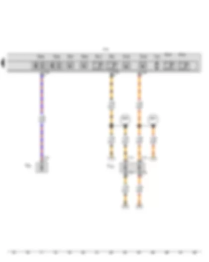
Wiring Diagram VW GOLF A7 2015 - Engine control unit - Mechatronic unit for dual clutch gearbox

| G487 | Gear selector movement sensor 1 |
| G488 | Gear selector movement sensor 2 |
| J623 | Engine control unit |
| J743 | Mechatronic unit for dual clutch gearbox |
| N215 | Automatic gearbox pressure regulating valve 1 |
| N216 | Automatic gearbox pressure regulating valve 2 |
| N217 | Automatic gearbox pressure regulating valve 3 |
| N218 | Automatic gearbox pressure regulating valve 4 |
| N233 | Automatic gearbox pressure regulating valve 5 |
| N371 | Automatic gearbox pressure regulating valve 6 |
| SB13 | Fuse 13 on fuse holder B |
| T16b | 16-pin connector |
| T17g | 17-pin connector |
| T17o | 17-pin connector |
| T94 | 94-pin connector |
| TIUL | Coupling point in interior, below left |
| 179 | Earth connection, in left headlight wiring harness |
| 673 | Earth point 3, on front of left longitudinal member |
| D51 | Positive connection 1 (15), in engine compartment wiring harness |
| D102 | Connection 2 in engine compartment wiring harness |
| * | see applicable current flow diagram for engine |
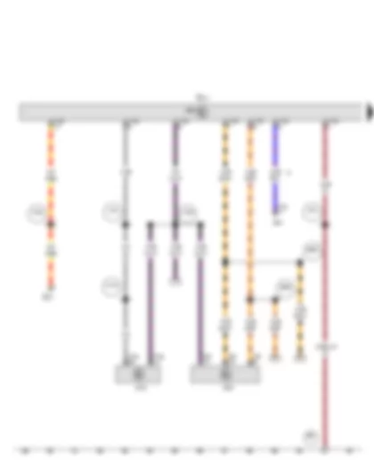
Wiring Diagram VW GOLF A7 2015 - Mechatronic unit for dual clutch gearbox
| G93 | Gearbox oil temperature sender |
| G193 | Automatic gearbox hydraulic pressure sender 1 |
| G194 | Automatic gearbox hydraulic pressure sender 2 |
| G195 | Gearbox output speed sender |
| G196 | Gearbox output speed sender 2 |
| G489 | Gear selector movement sensor 3 |
| G490 | Gear selector movement sensor 4 |
| G501 | Input shaft speed sender 1 |
| G502 | Input shaft speed sender 2 |
| G510 | Temperature sender in control unit |
| J743 | Mechatronic unit for dual clutch gearbox |
| T14h | 14-pin connector |
| T16b | 16-pin connector |
| T17e | 17-pin connector |
| T17m | 17-pin connector |
| TIUL | Coupling point in interior, below left |
| TML | Coupling point in engine compartment, left |
| V401 | Hydraulic pump motor |
| B384 | Connection 2 (powertrain CAN bus, high), in main wiring harness |
| B391 | Connection 2 (powertrain CAN bus, low), in main wiring harness |
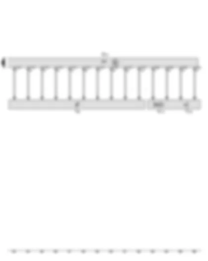
Wiring Diagram VW GOLF A7 2015 - Selector lever - Onboard supply control unit - Data bus diagnostic interface - Selector lever sensors control unit
| E313 | Selector lever |
| J519 | Onboard supply control unit |
| J527 | Steering column electronics control unit |
| J533 | Data bus diagnostic interface |
| J587 | Selector lever sensors control unit |
| SC7 | Fuse 7 on fuse holder C |
| T10s | 10-pin connector |
| T16r | 16-pin connector |
| T20 | 20-pin connector |
| T73a | 73-pin connector |
| T73c | 73-pin connector |
| 278 | Earth connection 4, in interior wiring harness |
| 687 | Earth point 1, on centre tunnel |
| A19 | Connection (58d), in dash panel wiring harness |
| A116 | Connection 2 (58d), in dash panel wiring harness |
| A164 | Positive connection 2 (30a) in dash panel wiring harness |
| A192 | Positive connection 3 (15a) in dash panel wiring harness |
| B383 | Connection 1 (powertrain CAN bus, high), in main wiring harness |
| B390 | Connection 1 (powertrain CAN bus, low), in main wiring harness |
| * | Cross section depends on equipment |
| *2 | According to equipment |
Wiring Diagram VW GOLF A7 2015 - Selector lever - Selector lever locked in position P switch - Selector lever sensors control unit - Selector lever lock solenoid - Selector lever position display
| E313 | Selector lever |
| F319 | Selector lever locked in position P switch |
| J587 | Selector lever sensors control unit |
| N110 | Selector lever lock solenoid |
| T4dr | 4-pin connector |
| T10t | 10-pin connector |
| Y26 | Selector lever position display |
| * | According to equipment |
Can't find your car? Check -> DiagnostData.com!


