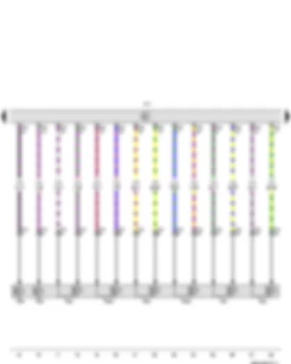
Wiring Diagram VW JETTA NF 2013 - Multifunction switch - Automatic gearbox control unit - Fuse 13 on fuse holder C - Fuse 20 on fuse holder C

| F125 | Multifunction switch |
| J217 | Automatic gearbox control unit |
| SC13 | Fuse 13 on fuse holder C |
| SC20 | Fuse 20 on fuse holder C |
| T10a | 10-pin connector |
| T52 | 52-pin connector |
| 114 | Earth connection, in automatic gearbox wiring harness |
| 641 | Earth point 3, left in engine compartment |
| A167 | Positive connection 3 (30a) in dash panel wiring harness |
| B172 | Positive connection 4 (30), in interior wiring harness |
| U8 | Positive connection (15a), in automatic gearbox wiring harness |
Wiring Diagram VW JETTA NF 2013 - Automatic gearbox control unit - Solenoid valve 1 - Solenoid valve 2 - Solenoid valve 3 - Solenoid valve 4 - Solenoid valve 5 - Solenoid valve 6 - Solenoid valve 9 - Solenoid valve 10
| J217 | Automatic gearbox control unit |
| N88 | Solenoid valve 1 |
| N89 | Solenoid valve 2 |
| N90 | Solenoid valve 3 |
| N91 | Solenoid valve 4 |
| N92 | Solenoid valve 5 |
| N93 | Solenoid valve 6 |
| N282 | Solenoid valve 9 |
| N283 | Solenoid valve 10 |
| T14 | 14-pin connector |
| T52 | 52-pin connector |
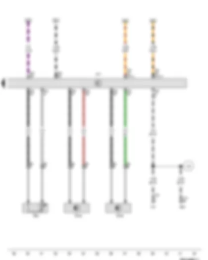
Wiring Diagram VW JETTA NF 2013 - Gearbox oil temperature sender - Gearbox input speed sender - Gearbox output speed sender - Automatic gearbox control unit - Engine control unit - Diagnostic connection
| G93 | Gearbox oil temperature sender |
| G182 | Gearbox input speed sender |
| G195 | Gearbox output speed sender |
| J217 | Automatic gearbox control unit |
| J623 | Engine control unit |
| T8 | 8-pin connector |
| T16 | 16-pin connector |
| T52 | 52-pin connector |
| T121 | 121-pin connector |
| U31 | Diagnostic connection |
| A76 | Connection (K-diagnosis wire), in dash panel wiring harness |
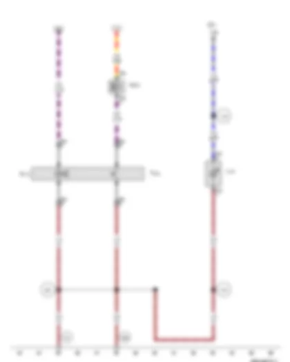
Wiring Diagram VW JETTA NF 2013 - Selector lever locked in position P switch - Selector lever lock solenoid - Ignition key withdrawal lock solenoid
| F319 | Selector lever locked in position P switch |
| L101 | Selector lever display illumination bulb |
| N110 | Selector lever lock solenoid |
| N376 | Ignition key withdrawal lock solenoid |
| SC7 | Fuse 7 on fuse holder C |
| T2fg | 2-pin connector |
| T2fk | 2-pin connector |
| T4n | 4-pin connector |
| 44 | Earth point, lower part of left A-pillar |
| 367 | Earth connection 2, in main wiring harness |
| 370 | Earth connection 5, in main wiring harness |
| 605 | Earth point, on top end of steering column |
| A19 | Connection (58d), in dash panel wiring harness |
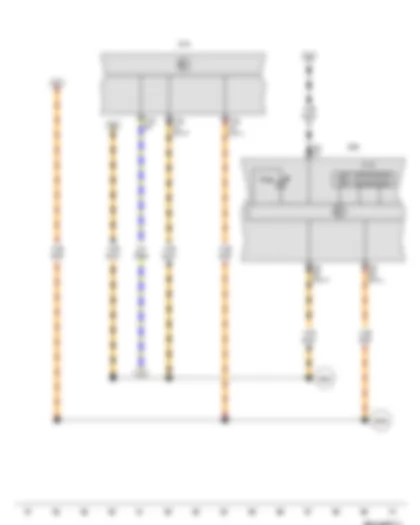
Wiring Diagram VW JETTA NF 2013 - Multifunction indicator - Control unit in dash panel insert - Onboard supply control unit - Selector lever lock warning lamp
| J119 | Multifunction indicator |
| J285 | Control unit in dash panel insert |
| J519 | Onboard supply control unit |
| K169 | Selector lever lock warning lamp |
| T32 | 32-pin connector |
| T73a | 73-pin connector |
| T73b | 73-pin connector |
| B383 | Connection 1 (powertrain CAN bus, high), in main wiring harness |
| B390 | Connection 1 (powertrain CAN bus, low), in main wiring harness |
Can't find your car? Check -> DiagnostData.com!


