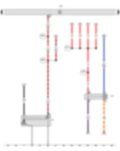
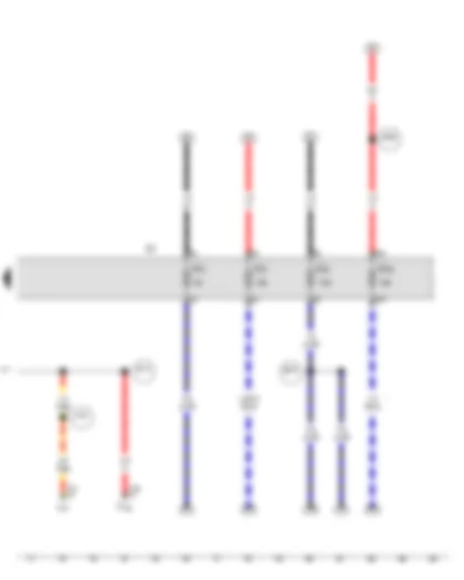
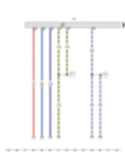
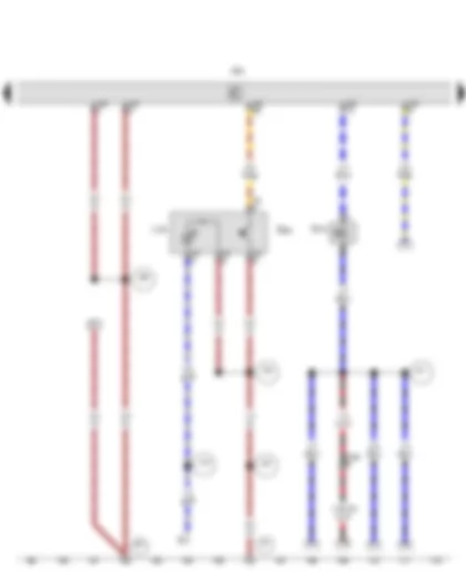
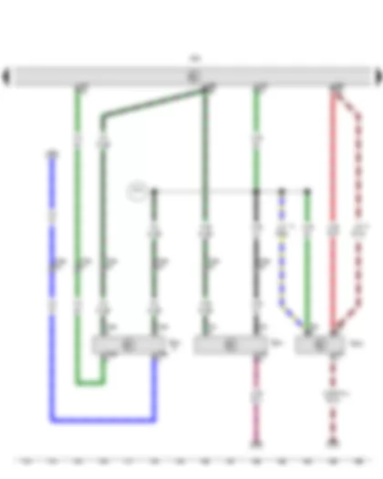
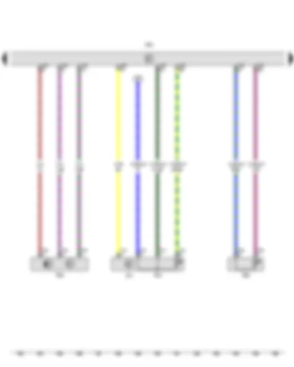
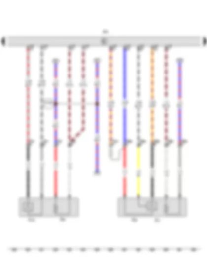
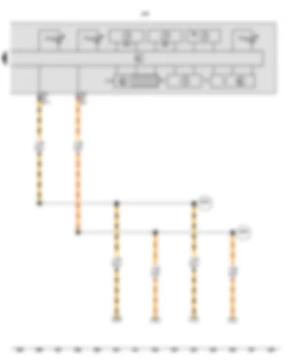
Wiring Diagram VW JETTA NF 2014 - Battery - Alternator - Voltage regulator - Onboard supply control unit - Fuse 1 in fuse holder A - Fuse 2 in fuse holder A - Fuse 5 in fuse holder A

| A | Battery |
| C | Alternator |
| C1 | Voltage regulator |
| J519 | Onboard supply control unit |
| SA | Fuse holder A |
| SA1 | Fuse 1 in fuse holder A |
| SA2 | Fuse 2 in fuse holder A |
| SA5 | Fuse 5 in fuse holder A |
| T2ay | 2-pin connector |
| T4 | 4-pin connector |
| T73 | 73-pin connector |
| 12 | Earth point, on left in engine compartment |
| 652 | Earth point, engine and gearbox earth |
| 714 | Earth point on right of engine |
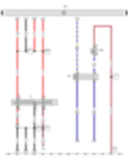
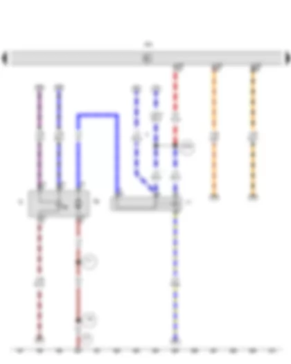
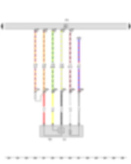
Wiring Diagram VW JETTA NF 2014 - Starter - Terminal 30 voltage supply relay - Onboard supply control unit
| B | Starter |
| J317 | Terminal 30 voltage supply relay |
| J519 | Onboard supply control unit |
| T73 | 73-pin connector |
| B169 | Positive connection 1 (30), in interior wiring harness |
| B170 | Positive connection 2 (30), in interior wiring harness |
| B239 | Positive connection 1 (50), in interior wiring harness |
| B240 | Positive connection 2 (50), in interior wiring harness |
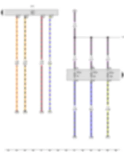
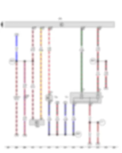
Wiring Diagram VW JETTA NF 2014 - Ignition/starter switch - X-contact relief relay - Onboard supply control unit - Shut-off valve relay 1 - Fuel tank shut-off valve 1
| D | Ignition/starter switch |
| J59 | X-contact relief relay |
| J519 | Onboard supply control unit |
| J651 | Shut-off valve relay 1 |
| N361 | Fuel tank shut-off valve 1 |
| T2y | 2-pin connector |
| T7 | 7-pin connector |
| 50 | Earth point, on left in luggage compartment |
| 377 | Earth connection 12, in main wiring harness |
| A33 | Connection (75), in dash panel wiring harness |
| B165 | Positive connection 2 (15), in interior wiring harness |
| B171 | Positive connection 3 (30), in interior wiring harness |
| B188 | Positive connection 5 (30), in interior wiring harness |
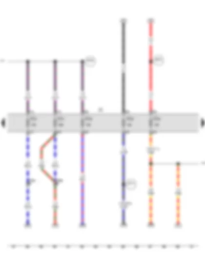
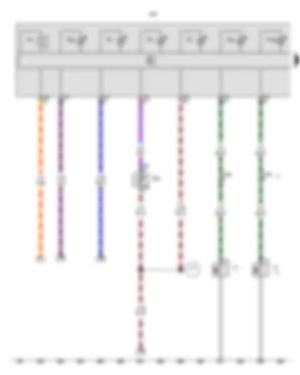
Wiring Diagram VW JETTA NF 2014 - Onboard supply control unit - Fuse holder C - Fuse 30 on fuse holder C - Fuse 32 on fuse holder C - Fuse 33 on fuse holder C
| J519 | Onboard supply control unit |
| SC | Fuse holder C |
| SC30 | Fuse 30 on fuse holder C |
| SC32 | Fuse 32 on fuse holder C |
| SC33 | Fuse 33 on fuse holder C |
| T73 | 73-pin connector |
| B146 | Positive connection 1 (87), in interior wiring harness |
Wiring Diagram VW JETTA NF 2014 - Fuse holder C - Fuse 20 on fuse holder C - Fuse 25 on fuse holder C - Fuse 28 on fuse holder C - Fuse 31 on fuse holder C - Fuse 41 on fuse holder C
| SC | Fuse holder C |
| SC20 | Fuse 20 on fuse holder C |
| SC25 | Fuse 25 on fuse holder C |
| SC28 | Fuse 28 on fuse holder C |
| SC31 | Fuse 31 on fuse holder C |
| SC41 | Fuse 41 on fuse holder C |
| T14a | 14-pin connector |
| B146 | Positive connection 1 (87), in interior wiring harness |
| B172 | Positive connection 4 (30), in interior wiring harness |
| B218 | Positive connection 6 (30), in interior wiring harness |
| E114 | Connection (air conditioning system, 15a), in dash panel wiring harness |
| * | From July 2015 |
| *2 | Cross section depends on equipment |
Wiring Diagram VW JETTA NF 2014 - Airbag coil connector and return ring with slip ring - Fuse holder C - Fuse 3 on fuse holder C - Fuse 4 on fuse holder C - Fuse 6 on fuse holder C - Fuse 24 on fuse holder C - Diagnostic connection
| F138 | Airbag coil connector and return ring with slip ring |
| SC | Fuse holder C |
| SC3 | Fuse 3 on fuse holder C |
| SC4 | Fuse 4 on fuse holder C |
| SC6 | Fuse 6 on fuse holder C |
| SC24 | Fuse 24 on fuse holder C |
| T16 | 16-pin connector |
| T16y | 16-pin connector |
| U31 | Diagnostic connection |
| A167 | Positive connection 3 (30a) in dash panel wiring harness |
| B172 | Positive connection 4 (30), in interior wiring harness |
| B278 | Positive connection 2 (15a) in main wiring harness |
| B302 | Positive connection 6 (30), in main wiring harness |
| * | From July 2015 |
Wiring Diagram VW JETTA NF 2014 - Engine control unit
| J623 | Engine control unit |
| T94 | 94-pin connector |
| 389 | Earth connection 24, in main wiring harness |
| B147 | Positive connection 2 (87), in interior wiring harness |
Wiring Diagram VW JETTA NF 2014 - Engine control unit - Switch illumination bulb - High-pressure valve for gas mode - Fuse 7 on fuse holder C
| E382 | Gas or petrol operating mode changeover switch |
| J623 | Engine control unit |
| L156 | Switch illumination bulb |
| N372 | High-pressure valve for gas mode |
| SC7 | Fuse 7 on fuse holder C |
| T6r | 6-pin connector |
| T14a | 14-pin connector |
| T94 | 94-pin connector |
| 44 | Earth point, lower part of left A-pillar |
| 234 | Earth connection in steering column switch wiring harness |
| 367 | Earth connection 2, in main wiring harness |
| 368 | Earth connection 3, in main wiring harness |
| 641 | Earth point 3, left in engine compartment |
| A19 | Connection (58d), in dash panel wiring harness |
| G11 | Positive connection (15), in gas mode wiring harness |
| * | Cross section depends on equipment |
Wiring Diagram VW JETTA NF 2014 - Tank pressure sensor - Gas rail sensor - Engine control unit
| G400 | Tank pressure sensor |
| G401 | Gas rail sensor |
| J623 | Engine control unit |
| T3s | 3-pin connector |
| T3x | 3-pin connector |
| T4ae | 4-pin connector |
| T14a | 14-pin connector |
| T94 | 94-pin connector |
| G12 | Connection 1 in gas mode wiring harness |
| * | Up to July 2015 |
| *2 | From July 2015 |
| *3 | Cross section depends on equipment |
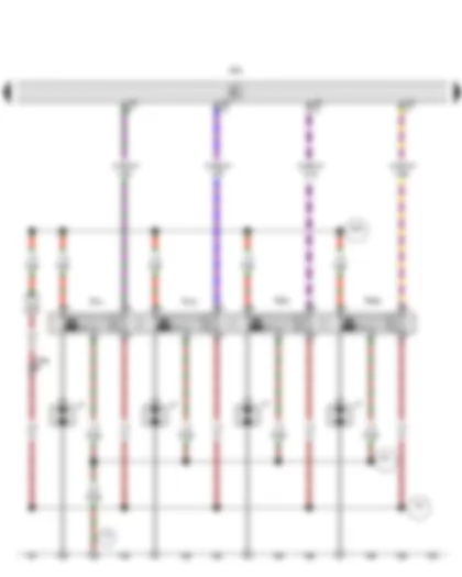
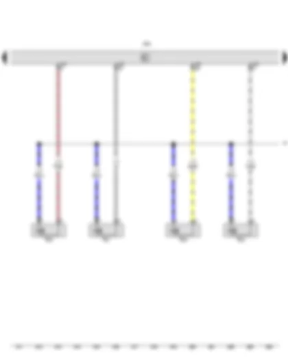
Wiring Diagram VW JETTA NF 2014 - Engine control unit - Ignition coil 1 with output stage - Ignition coil 2 with output stage - Ignition coil 3 with output stage - Ignition coil 4 with output stage - Spark plug connector
| J623 | Engine control unit |
| N70 | Ignition coil 1 with output stage |
| N127 | Ignition coil 2 with output stage |
| N291 | Ignition coil 3 with output stage |
| N292 | Ignition coil 4 with output stage |
| P | Spark plug connector |
| T14a | 14-pin connector |
| T60 | 60-pin connector |
| 15 | Earth point, on cylinder head |
| 85 | Earth connection 1, in engine compartment wiring harness |
| 221 | Earth connection (engine earth), in engine wiring harness |
| D25 | Positive connection (15), in engine prewiring harness |
| * | Cross section depends on equipment |
Wiring Diagram VW JETTA NF 2014 - High-pressure sender - Air conditioning system relay - Radiator fan control unit - Air conditioning system control unit - Engine control unit - Radiator fan
| G65 | High-pressure sender |
| J32 | Air conditioning system relay |
| J293 | Radiator fan control unit |
| J301 | Air conditioning system control unit |
| J623 | Engine control unit |
| N25 | Air conditioning system magnetic clutch |
| T2er | 2-pin connector |
| T3a | 3-pin connector |
| T3s | 3-pin connector |
| T4 | 4-pin connector |
| T10s | 10-pin connector |
| T94 | 94-pin connector |
| V7 | Radiator fan |
| 13 | Earth point, on right in engine compartment |
| 317 | Earth connection 7, in engine compartment wiring harness |
| 671 | Earth point 1, on front of left longitudinal member |
| * | Cross section depends on equipment |
Wiring Diagram VW JETTA NF 2014 - Hall sender - Throttle valve drive for electric throttle - Throttle valve drive angle sender 1 for electric throttle - Throttle valve drive angle sender 2 for electric throttle - Throttle valve module - Engine control unit
| G40 | Hall sender |
| G186 | Throttle valve drive for electric throttle |
| G187 | Throttle valve drive angle sender 1 for electric throttle |
| G188 | Throttle valve drive angle sender 2 for electric throttle |
| J338 | Throttle valve module |
| J623 | Engine control unit |
| T3a | 3-pin connector |
| T6ab | 6-pin connector |
| T60 | 60-pin connector |
| D112 | Connection 10 in engine compartment wiring harness |
| * | Cross section depends on equipment |
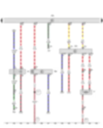
Wiring Diagram VW JETTA NF 2014 - Knock sensor 1 - Accelerator position sender - Accelerator position sender 2 - Engine control unit - Activated charcoal filter solenoid valve 1 - Camshaft control valve 1
| G61 | Knock sensor 1 |
| G79 | Accelerator position sender |
| G185 | Accelerator position sender 2 |
| J623 | Engine control unit |
| N80 | Activated charcoal filter solenoid valve 1 |
| N205 | Camshaft control valve 1 |
| T2d | 2-pin connector |
| T2e | 2-pin connector |
| T6q | 6-pin connector |
| T60 | 60-pin connector |
| T94 | 94-pin connector |
| D102 | Connection 2 in engine compartment wiring harness |
| * | Cross section depends on equipment |
| *2 | From July 2015 |
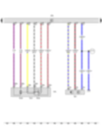
Wiring Diagram VW JETTA NF 2014 - Engine speed sender - Coolant temperature sender - Intake manifold pressure sender - Engine control unit
| G28 | Engine speed sender |
| G42 | Intake air temperature sender |
| G62 | Coolant temperature sender |
| G71 | Intake manifold pressure sender |
| J623 | Engine control unit |
| T2b | 2-pin connector |
| T3b | 3-pin connector |
| T4w | 4-pin connector |
| T60 | 60-pin connector |
| * | Cross section depends on equipment |
Wiring Diagram VW JETTA NF 2014 - Fuel gauge sender - Fuel system pressurisation pump - Fuel pump relay - Engine control unit
| G | Fuel gauge sender |
| G6 | Fuel system pressurisation pump |
| J17 | Fuel pump relay |
| J623 | Engine control unit |
| T5 | 5-pin connector |
| T94 | 94-pin connector |
| 43 | Earth point, lower part of right A-pillar |
| 199 | Earth connection 3, in dash panel wiring harness |
| 371 | Earth connection 6, in main wiring harness |
| B156 | Positive connection (30a), in interior wiring harness |
| * | Up to July 2015 |
| *2 | From July 2015 |
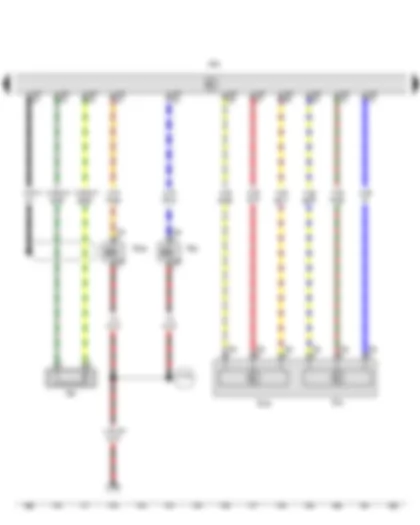
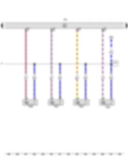
Wiring Diagram VW JETTA NF 2014 - Engine control unit - Injector - cylinder 1 - Injector - cylinder 2 - Injector - cylinder 3 - Injector - cylinder 4
| J623 | Engine control unit |
| N30 | Injector, cylinder 1 |
| N31 | Injector, cylinder 2 |
| N32 | Injector, cylinder 3 |
| N33 | Injector, cylinder 4 |
| T60 | 60-pin connector |
| D95 | Connection (injectors), in engine compartment wiring harness |
Wiring Diagram VW JETTA NF 2014 - Engine control unit - Gas injection valve 1 - Gas injection valve 2 - Gas injection valve 3 - Gas injection valve 4
| J623 | Engine control unit |
| N366 | Gas injection valve 1 |
| N367 | Gas injection valve 2 |
| N368 | Gas injection valve 3 |
| N369 | Gas injection valve 4 |
| T60 | 60-pin connector |
| D95 | Connection (injectors), in engine compartment wiring harness |
Wiring Diagram VW JETTA NF 2014 - Lambda probe - Lambda probe after catalytic converter - Engine control unit - Lambda probe heater - Lambda probe 1 heater after catalytic converter
| G39 | Lambda probe |
| G130 | Lambda probe after catalytic converter |
| J623 | Engine control unit |
| T4w | 4-pin connector |
| T6ab | 6-pin connector |
| T94 | 94-pin connector |
| Z19 | Lambda probe heater |
| Z29 | Lambda probe 1 heater after catalytic converter |
| D189 | Connection (87a) in engine prewiring harness |
| * | From July 2015 |
Wiring Diagram VW JETTA NF 2014 - Lambda probe - Engine control unit - Lambda probe heater
| G39 | Lambda probe |
| J623 | Engine control unit |
| T6ab | 6-pin connector |
| T94 | 94-pin connector |
| Z19 | Lambda probe heater |
| * | From July 2015 |
Wiring Diagram VW JETTA NF 2014 - Brake light switch - Clutch pedal switch - Brake pedal switch - Evaporator output temperature sender - Engine control unit
| F | Brake light switch |
| F36 | Clutch pedal switch |
| F47 | Brake pedal switch |
| G263 | Evaporator output temperature sender |
| J623 | Engine control unit |
| T4d | 4-pin connector |
| T4f | 4-pin connector |
| T14a | 14-pin connector |
| T94 | 94-pin connector |
| 417 | Earth connection 9, in engine compartment wiring harness |
| B350 | Positive connection 1 (87a) in main wiring harness |
| B453 | Connection 1 (sensor), in main wiring harness |
| B633 | Connection (brake pedal switch), in main wiring harness |
| * | Cross section depends on equipment |
Wiring Diagram VW JETTA NF 2014 - Oil pressure switch - Coolant shortage indicator sender - Buzzer and gong - Control unit in dash panel insert - Natural gas mode warning lamp
| F1 | Oil pressure switch |
| G32 | Coolant shortage indicator sender |
| H3 | Buzzer and gong |
| J285 | Control unit in dash panel insert |
| K2 | Alternator warning lamp |
| K3 | Oil pressure warning lamp |
| K28 | Coolant temperature and coolant shortage warning lamp |
| K31 | Cruise control system warning lamp |
| K83 | Exhaust emissions warning lamp |
| K192 | Natural gas mode warning lamp |
| T1g | Single connector |
| T2s | 2-pin connector |
| T14a | 14-pin connector |
| T32 | 32-pin connector |
| 410 | Earth connection 1 (sender earth) in main wiring harness |
| * | Up to July 2015 |
| *2 | From July 2015 |
Wiring Diagram VW JETTA NF 2014 - Fuel gauge - Rev. counter - Speedometer - Natural gas gauge - Multifunction indicator - Control unit in dash panel insert - Trip counter
| G1 | Fuel gauge |
| G5 | Rev. counter |
| G21 | Speedometer |
| G411 | Natural gas gauge |
| J119 | Multifunction indicator |
| J285 | Control unit in dash panel insert |
| K105 | Reserve fuel warning lamp |
| K132 | Electronic power control fault lamp |
| T32 | 32-pin connector |
| Y4 | Trip counter |
| B383 | Connection 1 (powertrain CAN bus, high), in main wiring harness |
| B390 | Connection 1 (powertrain CAN bus, low), in main wiring harness |
Buy a pack of several access activations at a discount
-40%
PACK OF - 5 - CARS
| Online access | ✔ |
| Lifetime Access | ✔ |
Enable Access
-45%
PACK OF - 10 - CARS
| Online access | ✔ |
| Lifetime Access | ✔ |
Enable Access
-50%
PACK OF - 25 - CARS
| Online access | ✔ |
| Lifetime Access | ✔ |
Enable Access
-55%
PACK OF - 50 - CARS
| Online access | ✔ |
| Lifetime Access | ✔ |
Enable Access
Can't find your car? Check -> DiagnostData.com!

