AUTOMOTIVE ELECTRICIANS PORTAL

VW CADDY 2011 — Radiator fan . Wiring diagrams, Pin Connector, Location

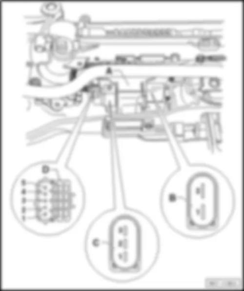
Wiring Diagram VW CADDY 2011 - Radiator fan control unit - Engine control unit - Fuse 3 in fuse holder A - Radiator fan on right of radiator


Wiring Diagram  VW CADDY 2011 - Radiator fan control unit - Engine control unit - Fuse 3 in fuse holder A - Radiator fan on right of radiator https://portal-diagnostov.com/license.html
https://portal-diagnostov.com/license.html Automotive Electricians Portal FZCO Automotive Electricians Portal FZCO
Download PDF file
J293 Radiator fan control unit
J623 Engine control unit
SA3 Fuse 3 in fuse holder A
SB24 Fuse 24 on fuse holder B
T2hl 2-pin connector
T4x 4-pin connector, on radiator fan, bottom left
T40 40-pin connector
T94 94-pin connector
T121 121-pin connector
V7 Radiator fan
V35 Radiator fan on right of radiator
  640 Earth point 2, left in engine compartment
  D111 Connection 9 in engine compartment wiring harness
  D180 Connection (87a), in engine compartment wiring harness
*see applicable current flow diagram for engine
*2Cross-section 4.0 possible
*3Only models with petrol engine
*4Only models with diesel engines
*5Only models with 1.6l engine
*6Only models with 2.0l engine
*7Only models with natural gas engine
*8Only models with auxiliary fan


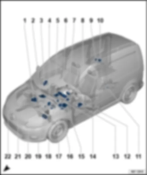
VW CADDY 2011 Overview of all control units

Overview of all control units
VW CADDY 2011 Overview of all control units https://portal-diagnostov.com/license.html
https://portal-diagnostov.com/license.html Automotive Electricians Portal FZCO Automotive Electricians Portal FZCO
Получить доступ ко всем электросхемам автомобиляDownload PDF file
1 -  ABS control unit -J104-
q   Fitting location → Chapter
q   Connector assignment → Chapter
2 -  Engine control unit -J623-
q   Fitting location → Chapter
q   Connector assignment for 121-pin connector -T121- → Chapter
q   Connector assignment for 60-pin connector -T60- and 94-pin connector -T94- → Chapter
3 -  Front passenger door control unit -J387-
q   Fitting location → Chapter
q   Connector assignment → Chapter
4 -  Control unit for cornering light and headlight range control -J745-
q   Fitting location → Chapter
5 -  Mobile telephone operating electronics control unit -J412-
q   Fitting location → Chapter
q   Connector assignment → Chapter
6 -  Control unit in dash panel insert -J285-
q   Connector assignment → Chapter
7 -  Steering column electronics control unit -J527-
q   Fitting location → Chapter
q   Connector assignment → Chapter
8 -  Data bus diagnostic interface -J533-
q   Fitting location → Chapter
q   Connector assignment → Chapter
9 -  Trailer detector control unit -J345-
q   Fitting location → Chapter
q   Connector assignment → Chapter
10 -  Parking aid control unit -J446- (2JB )
q   Fitting location → Chapter
11 -  All-wheel drive control unit -J492-
q   Fitting location → Chapter
12 -  Heated front seats control unit -J774-
q   Fitting location → Chapter
13 -  Driver door control unit -J386-
q   Fitting location → Chapter
q   Connector assignment → Chapter
14 -  Remote control receiver for auxiliary coolant heater -R149-
q   Fitting location → Chapter
15 -  Onboard supply control unit -J519-
q   Fitting location → Chapter
q   Connector assignment of 52-pin connector -T52a- black → Chapter
q   Connector assignment of 52-pin connector -T52b- white → Chapter
q   Connector assignment of 52-pin connector -T52c- brown → Chapter
16 -  Park assist steering control unit -J791- (7X5 ),Parking aid control unit -J446- (2JG, 2JX )
q   Fitting location → Chapter
q   Connector assignment → Chapter
17 -  Voltage stabiliser -J532-
q   Fitting location → Chapter
18 -  Special vehicle control unit -J608-
q   Fitting location → Chapter
19 -  Power steering control unit -J500-
q   Fitting location → Chapter
q   Connector assignment → Chapter
20 -  Airbag control unit -J234-
q   Fitting location → Chapter
q   Connector assignment → Chapter
21 -  Battery monitoring control unit -J367-
q   Fitting location → Chapter
22 -  Wiper motor control unit -J400-
q   Fitting location → Chapter


VW CADDY 2011 Engine control unit J623

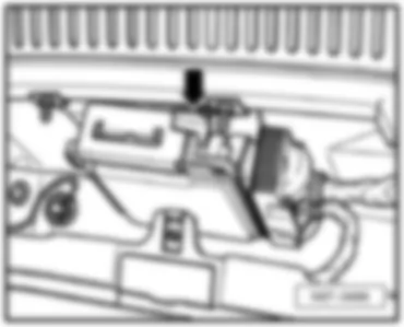
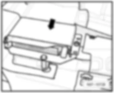
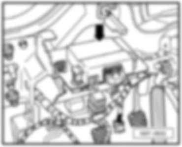
Engine control unit -J623-
   
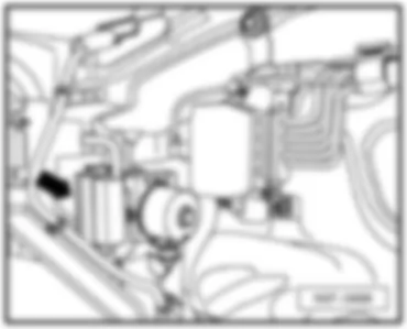
Fitting location:
under plenum chamber cover, centre -arrow-
 
VW CADDY 2011 Engine control unit J623 https://portal-diagnostov.com/license.html
https://portal-diagnostov.com/license.html Automotive Electricians Portal FZCO Automotive Electricians Portal FZCO
Получить доступ ко всем электросхемам автомобиляDownload PDF file
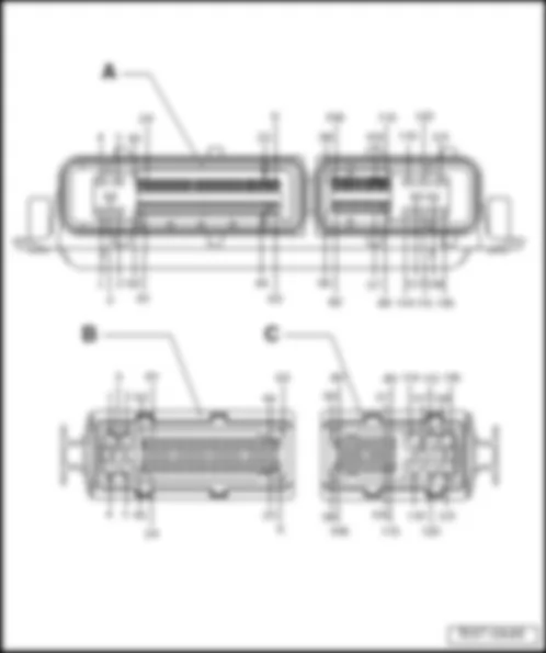
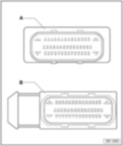
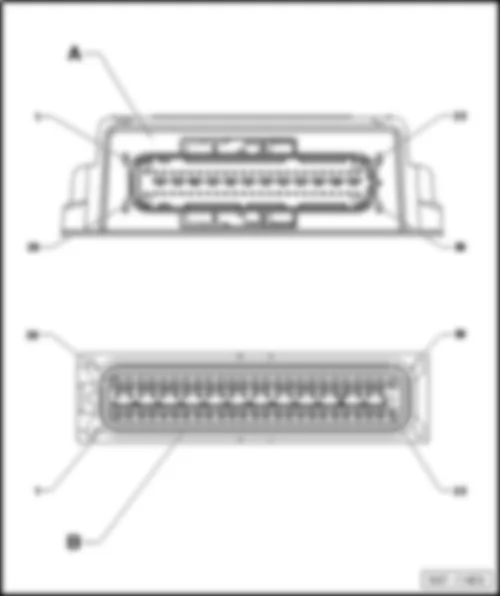
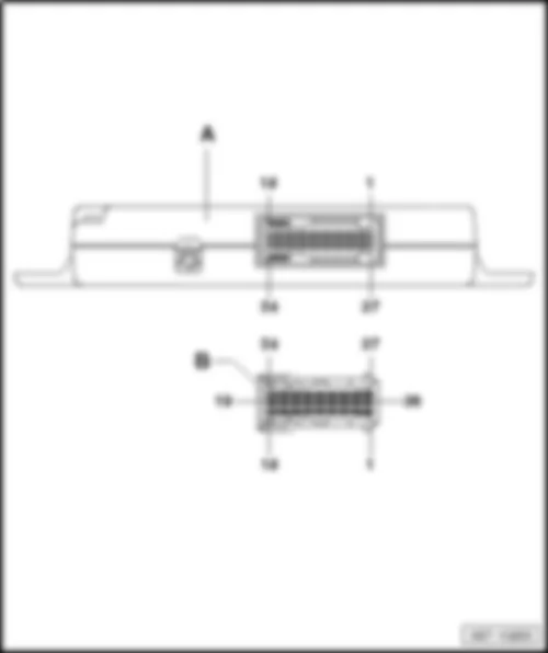
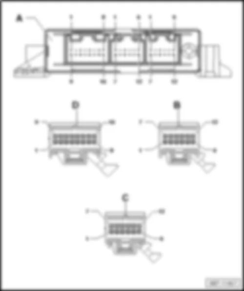
121-pin connector assignment:
VW CADDY 2011 Engine control unit J623 https://portal-diagnostov.com/license.html
https://portal-diagnostov.com/license.html Automotive Electricians Portal FZCO Automotive Electricians Portal FZCO
Получить доступ ко всем электросхемам автомобиляDownload PDF file
A -  Engine control unit -J623-
Connector:
B -  81-pin connector -T81- (Pin 1 - Pin 81)
C -  40-pin connector -T40- (Pin 82 - Pin 121)
  Note
The 40-pin connector -T40- and the 81-pin connector -T81- are represented in the wiring diagram as a 121-pin connector -T121- .

Back to overview → Chapter
   
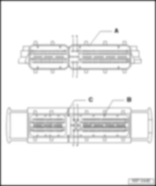
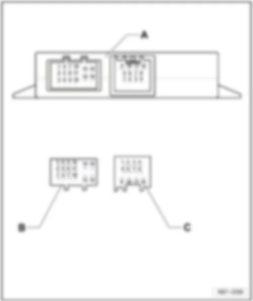
154-pin connector assignment:
VW CADDY 2011 Engine control unit J623 https://portal-diagnostov.com/license.html
https://portal-diagnostov.com/license.html Automotive Electricians Portal FZCO Automotive Electricians Portal FZCO
Получить доступ ко всем электросхемам автомобиляDownload PDF file
A -  Engine control unit -J623-
Connector:
B -  94-pin connector -T94-
C -  60-pin connector -T60-

Back to overview → Chapter
Power steering control unit -J500-
   
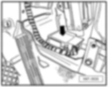
Fitting location:
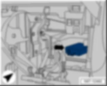
On steering on centre of assembly carrier -arrow-
 
VW CADDY 2011 Engine control unit J623 https://portal-diagnostov.com/license.html
https://portal-diagnostov.com/license.html Automotive Electricians Portal FZCO Automotive Electricians Portal FZCO
Получить доступ ко всем электросхемам автомобиляDownload PDF file
Connector assignment:
VW CADDY 2011 Engine control unit J623 https://portal-diagnostov.com/license.html
https://portal-diagnostov.com/license.html Automotive Electricians Portal FZCO Automotive Electricians Portal FZCO
Получить доступ ко всем электросхемам автомобиляDownload PDF file
A -  Power steering control unit -J500-
Connector:
B -  2-pin connector -T2b-
C -  3-pin connector -T3o-
D -  5-pin connector -T5s-

Back to overview → Chapter


VW CADDY 2011 ABS control unit J104

ABS control unit -J104-
   
Fitting location:
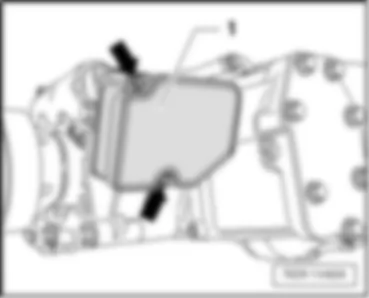
On bulkhead, in​ engine​ compart., right​ -arrow-
 
VW CADDY 2011 ABS control unit J104 https://portal-diagnostov.com/license.html
https://portal-diagnostov.com/license.html Automotive Electricians Portal FZCO Automotive Electricians Portal FZCO
Получить доступ ко всем электросхемам автомобиляDownload PDF file
Connector assignment:
VW CADDY 2011 ABS control unit J104 https://portal-diagnostov.com/license.html
https://portal-diagnostov.com/license.html Automotive Electricians Portal FZCO Automotive Electricians Portal FZCO
Получить доступ ко всем электросхемам автомобиляDownload PDF file
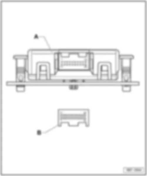
A -  ABS control unit -J104-
q   with ESP only
Connector:
B -  47-pin connector, on wiring harness (T47)

Back to overview → Chapter


VW CADDY 2011 Airbag control unit J234

Airbag control unit -J234-
   
Fitting location:
Under centre console -arrow-
 
VW CADDY 2011 Airbag control unit J234 https://portal-diagnostov.com/license.html
https://portal-diagnostov.com/license.html Automotive Electricians Portal FZCO Automotive Electricians Portal FZCO
Получить доступ ко всем электросхемам автомобиляDownload PDF file
Connector assignment:
VW CADDY 2011 Airbag control unit J234 https://portal-diagnostov.com/license.html
https://portal-diagnostov.com/license.html Automotive Electricians Portal FZCO Automotive Electricians Portal FZCO
Получить доступ ко всем электросхемам автомобиляDownload PDF file
A -  Airbag control unit -J234-
Connector:
B -  50-pin connector -T50-

Back to overview → Chapter


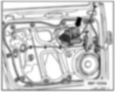
VW CADDY 2011 Front passenger door control unit J387

Front passenger door control unit -J387-
   
Fitting location:
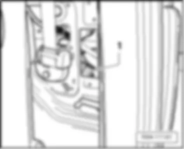
On door inner part on front right -arrow-
  Note
Illustration shows left side. The right side is similar.
 
VW CADDY 2011 Front passenger door control unit J387 https://portal-diagnostov.com/license.html
https://portal-diagnostov.com/license.html Automotive Electricians Portal FZCO Automotive Electricians Portal FZCO
Получить доступ ко всем электросхемам автомобиляDownload PDF file
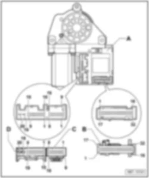
Connector assignment:
VW CADDY 2011 Front passenger door control unit J387 https://portal-diagnostov.com/license.html
https://portal-diagnostov.com/license.html Automotive Electricians Portal FZCO Automotive Electricians Portal FZCO
Получить доступ ко всем электросхемам автомобиляDownload PDF file
A -  Front passenger door control unit -J387-
Connector:
B -  32-pin connector -T32a-
C -  16-pin connector -T16g-
D -  20-pin connector -T20b-

Back to overview → Chapter


VW CADDY 2011 Mobile telephone operating electronics control unit J412

Mobile telephone operating electronics control unit -J412-
Fitting location:
Under seat on front right -arrow -
 
VW CADDY 2011 Mobile telephone operating electronics control unit J412 https://portal-diagnostov.com/license.html
https://portal-diagnostov.com/license.html Automotive Electricians Portal FZCO Automotive Electricians Portal FZCO
Получить доступ ко всем электросхемам автомобиляDownload PDF file
Connector assignment
VW CADDY 2011 Mobile telephone operating electronics control unit J412 https://portal-diagnostov.com/license.html
https://portal-diagnostov.com/license.html Automotive Electricians Portal FZCO Automotive Electricians Portal FZCO
Получить доступ ко всем электросхемам автомобиляDownload PDF file
A -  Mobile telephone operating electronics control unit -J412-
Connector:
B -  54-pin connector -T54-

Back to overview → Chapter


VW CADDY 2011 Special vehicle control unit J608

Special vehicle control unit -J608-
Fitting location:
Above the Airbag control unit -arrow-
Back to overview → Chapter
 
VW CADDY 2011 Special vehicle control unit J608 https://portal-diagnostov.com/license.html
https://portal-diagnostov.com/license.html Automotive Electricians Portal FZCO Automotive Electricians Portal FZCO
Получить доступ ко всем электросхемам автомобиляDownload PDF file


VW CADDY 2011 Trailer detector control unit J345

Trailer detector control unit -J345-
Fitting location:
In rear right side panel -arrow-
 
VW CADDY 2011 Trailer detector control unit J345 https://portal-diagnostov.com/license.html
https://portal-diagnostov.com/license.html Automotive Electricians Portal FZCO Automotive Electricians Portal FZCO
Получить доступ ко всем электросхемам автомобиляDownload PDF file
Connector assignment:
VW CADDY 2011 Trailer detector control unit J345 https://portal-diagnostov.com/license.html
https://portal-diagnostov.com/license.html Automotive Electricians Portal FZCO Automotive Electricians Portal FZCO
Получить доступ ко всем электросхемам автомобиляDownload PDF file
A -  Trailer detector control unit -J345-
Connector:
B -  16-pin connector -T16x-
C -  12-pin connector -T12m-

Back to overview → Chapter


VW CADDY 2011 Heated front seats control unit J774

Heated front seats control unit -J774-
Fitting location:
on front left of seat frame -arrow-
Back to overview → Chapter


VW CADDY 2011 Steering column electronics control unit J527

Steering column electronics control unit -J527-
Fitting location:
under steering column, near steering column switch -1-
 
VW CADDY 2011 Steering column electronics control unit J527 https://portal-diagnostov.com/license.html
https://portal-diagnostov.com/license.html Automotive Electricians Portal FZCO Automotive Electricians Portal FZCO
Получить доступ ко всем электросхемам автомобиляDownload PDF file
Connector assignment → Chapter
VW CADDY 2011 Steering column electronics control unit J527 https://portal-diagnostov.com/license.html
https://portal-diagnostov.com/license.html Automotive Electricians Portal FZCO Automotive Electricians Portal FZCO
Получить доступ ко всем электросхемам автомобиляDownload PDF file
1 -  Steering column electronics control unit -J527-
q   under steering column, near steering column switch

   
Connector assignment:
VW CADDY 2011 Steering column electronics control unit J527 https://portal-diagnostov.com/license.html
https://portal-diagnostov.com/license.html Automotive Electricians Portal FZCO Automotive Electricians Portal FZCO
Получить доступ ко всем электросхемам автомобиляDownload PDF file
A -  16-pin connector -T16a-
1 - Terminal 30
2 - Terminal 31
3 - connector 1 (convenience CAN bus, low), in main wiring harness -B406-
4 - connector 1 (convenience CAN bus, low), in main wiring harness -B397-
5 - Engine control unit -J623- (CCS off)
6 - Onboard supply control unit -J519- or Engine control unit -J623- (terminal 50)
7 - Not assigned
8 - Not assigned
9 - Not assigned
10 - Not assigned
11 - Selector lever sensors control unit -J587- (P)
12 - Not assigned
13 - Not assigned
14 - Onboard supply control unit -J519- (terminal 15)
15 - Not assigned
16 - Not assigned
B -  4-pin connector, yellow -T4k-
1 - Airbag 1 -
2 - Airbag 1 +
3 - Not assigned
4 - Not assigned

Back to overview → Chapter


VW CADDY 2011 Parking aid control unit J446

Parking aid control unit -J446-
Fitting location:
behind rear right side trim -arrow-
Back to overview → Chapter
 
VW CADDY 2011 Parking aid control unit J446 https://portal-diagnostov.com/license.html
https://portal-diagnostov.com/license.html Automotive Electricians Portal FZCO Automotive Electricians Portal FZCO
Получить доступ ко всем электросхемам автомобиляDownload PDF file


VW CADDY 2011 All-wheel drive control unit J492

All-wheel drive control unit -J492-
Fitting location:
On rear final drive -arrow-
Back to overview → Chapter
 
VW CADDY 2011 All-wheel drive control unit J492 https://portal-diagnostov.com/license.html
https://portal-diagnostov.com/license.html Automotive Electricians Portal FZCO Automotive Electricians Portal FZCO
Получить доступ ко всем электросхемам автомобиляDownload PDF file


VW CADDY 2011 Driver door control unit J386

Driver door control unit -J386-
Fitting location:
On door inner part on front left -arrow-
 
VW CADDY 2011 Driver door control unit J386 https://portal-diagnostov.com/license.html
https://portal-diagnostov.com/license.html Automotive Electricians Portal FZCO Automotive Electricians Portal FZCO
Получить доступ ко всем электросхемам автомобиляDownload PDF file
Connector assignment:
VW CADDY 2011 Driver door control unit J386 https://portal-diagnostov.com/license.html
https://portal-diagnostov.com/license.html Automotive Electricians Portal FZCO Automotive Electricians Portal FZCO
Получить доступ ко всем электросхемам автомобиляDownload PDF file
A -  Driver door control unit -J386-
Connector:
B -  32-pin connector -T32b- (only vehicles with window regulator)
 -  16-pin connector -T16e- (only for vehicles without window regulator, not shown)
C -  16-pin connector -T16f-
D -  20-pin connector -T20a-

Back to overview → Chapter


VW CADDY 2011 Onboard supply control unit J519

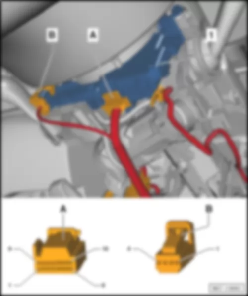
Onboard supply control unit -J519-
Fitting location:
Below the left dash panel, between the relay carriers-D-
Connector assignment, 52-pin connector, black -T52a- → Chapter
Connector assignment, 52-pin connector, white -T52b- → Chapter
Connector assignment, 52-pin connector, brown -T52c- → Chapter
   
VW CADDY 2011 Onboard supply control unit J519 https://portal-diagnostov.com/license.html
https://portal-diagnostov.com/license.html Automotive Electricians Portal FZCO Automotive Electricians Portal FZCO
Получить доступ ко всем электросхемам автомобиляDownload PDF file

Connector assignment:
   
52-pin connector -T52a- black -A-
VW CADDY 2011 Onboard supply control unit J519 https://portal-diagnostov.com/license.html
https://portal-diagnostov.com/license.html Automotive Electricians Portal FZCO Automotive Electricians Portal FZCO
Получить доступ ко всем электросхемам автомобиляDownload PDF file
1 -  Fuse 26 on fuse holder B -SB26- (Terminal 30a)
t  Onboard supply control unit -J519-
t  Left fog light bulb -L22- , or left cornering light bulb -L148-
t  Rear left fog light bulb -L46- , or rear right fog light bulb -L47-
t  Left daytime running light bulb -L174-
t  Right side light bulb -M3-
t  Left tail light bulb -M4-
t  Front left turn signal bulb -M5-
t  Rear right turn signal bulb -M8-
t  Right brake light bulb -M10-
t  Left reversing light bulb -M16-
t  Right turn signal repeater bulb -M19-
t  Left headlight dipped beam bulb -M29-
t  Left headlight main beam bulb -M30-
2 -  -
3 -  Right turn signal repeater bulb -M19-
4 -  Left turn signal repeater bulb -M18-
5 -  Left headlight main beam bulb -M30-
6 -  Left daytime running light bulb -L174- (2-filament light bulb)
7 -  -
8 -  -
9 -  Rear right turn signal bulb -M8-
10 -  Front left turn signal bulb -M5-
11 -  Left headlight dipped beam bulb -M29-
12 -  Connection (door contact switch), in rear wiring harness -W22- , luggage compartment light switch -F5- , rear lid lock unit -F256- , luggage compartment light -W3-
13 -  Rear lid handle release button -E234-
14 -  Bonnet contact switch -F266-
15 -  Rear right central locking lock unit -F223-
16 -  Reversing light switch -F4-
17 -  Rear fog light switch -E18-
18 -  Light switch -E1- (Daytime running light)
19 -  Light switch -E1- (Side lights)
20 -  Light switch -E1- (Driving light assist)
21 -  Fog light switch -E7-
22 -  Light switch -E1- (Headlight dipped beam)
23 -  Earth connection -31-
24 -  Fuse 3 on fuse holder B -SB3- (terminal 30_ref)
25 -  Left fog light bulb -L22- , left cornering light bulb -L148-
26 -  Right brake light bulb -M10-
27 -  Left tail light bulb -M4- (2-filament light bulb)
28 -  Left reversing light bulb -M16-
29 -  Contact switch for rear left door -F227- , rear lid lock unit -F256-
30 -  Rear right door contact switch -F11-
31 -  -
32 -  Rear left interior locking button -E310-
33 -  Interior illumination switch -E599- , Rear left door lock unit -VX23- , Surround lighting 1 in rear lid -W61- , Surround lighting 2 in rear lid -W62-
34 -  Rear left central locking lock unit -F222-
35 -  Heater/heat output switch -E16-
36 -  Interior monitoring deactivation switch -E267-
37 -  -
38 -  Rear left central locking lock unit -F222-
39 -  -
40 -  Rear right central locking lock unit -F223-
41 -  Rear left door contact switch -F10-
42 -  Earth connection -31-
43 -  Washer pump -V5- , Rear window wiper motor -V12- , windscreen and rear window washer pump -V59-
44 -  Right side light bulb -M3- (2-filament light bulb)
45 -  High-mounted brake light bulb -M25-
46 -  Rear lid release motor -V139-
47 -  -
48 -  Left sliding door central locking motor -V95-
49 -  Right sliding door central locking motor -V58-
50 -  -
51 -  -
52 -  -

Back to overview → Chapter
   
52-pin connector -T52b- white-B-
VW CADDY 2011 Onboard supply control unit J519 https://portal-diagnostov.com/license.html
https://portal-diagnostov.com/license.html Automotive Electricians Portal FZCO Automotive Electricians Portal FZCO
Получить доступ ко всем электросхемам автомобиляDownload PDF file
1 -  Fuse 50 on fuse holder C -SC50- (terminal 30_ZV)
2 -  Washer pump -V5- , Rear window wiper motor -V12- , windscreen and rear window washer pump -V59-
3 -  -
4 -  -
5 -  Rear left door lock unit -VX23-
6 -  -
7 -  Left sliding door central locking motor -V95-
8 -  Right sliding door central locking motor -V58-
9 -  -
10 -  -
11 -  Rear lid release motor -V139-
12 -  Terminal 15 voltage supply relay -J329-
13 -  -
14 -  Heater/heat output switch -E16-
15 -  Switch and instrument illumination regulator -E20-
16 -  Rear left interior locking button -E310-
17 -  -
18 -  -
19 -  -
20 -  -
21 -  Heated front seats control unit -J774-
22 -  Heated rear window relay -J9-
23 -  -
24 -  Indicator lamp for hazard warning light -K6-
25 -  -
26 -  -
27 -  -
28 -  X-contact relief relay -J59-
29 -  Engine control unit -J623- , terminal 50 voltage supply relay -J682-
30 -  Switch and instrument illumination regulator -E20-
31 -  -
32 -  -
33 -  Wiper motor control unit -J400- , rain and light sensor -G397- (LIN bus)
34 -  -
35 -  -
36 -  Alarm horn -H12- , interior monitoring sensor -G273- , vehicle inclination sender -G384- , Anti-theft alarm sensor -G578- (LIN bus)
37 -  Interior monitoring deactivation switch -E267-
38 -  Fuel pump relay -J17-Fuel supply relay -J643-
39 -  -
40 -  Headlight washer system relay -J39-
41 -  Horn relay -J413-
42 -  Fuse 46 on fuse holder C -Klemme- 30a
t  Front interior light -W1-
t  Luggage compartment light -W3-
t  Glove compartment light -W6-
t  Rear interior light -W43-
43 -  (Terminal 30g)
t  Front interior light -W1-
t  Luggage compartment light -W3-
t  Glove compartment light -W6-
t  Rear interior light -W43-
44 -  -
45 -  -
46 -  -
47 -  -
48 -  -
49 -  -
50 -  Rear left fog light bulb -L46- (2-filament light bulb) or rear right fog light bulb -L47- (2-filament light bulb)
51 -  Terminal -58d-
52 -  Earth connection -31-

Back to overview → Chapter
   
52-pin connector -T52c- brown -C-
VW CADDY 2011 Onboard supply control unit J519 https://portal-diagnostov.com/license.html
https://portal-diagnostov.com/license.html Automotive Electricians Portal FZCO Automotive Electricians Portal FZCO
Получить доступ ко всем электросхемам автомобиляDownload PDF file
1 -  Fuse 24 on fuse holder C -SC24- (terminal 30DWA)
t  Alarm horn -H12-
t  Interior monitoring sensor -G273-
2 -  -
3 -  Right tail light bulb -M2- (2-filament light bulb)
4 -  Left brake light bulb -M9-
5 -  Earth connection -31-
6 -  -
7 -  Hazard warning lights button -E229-
8 -  -
9 -  -
10 -  Front interior light -W1- , Rear interior light -W43-Terminal -TK-
11 -  -
12 -  -
13 -  Steering column electronics control unit -J527-Terminal -15-
14 -  Steering column electronics control unit -J527-Terminal -50-
15 -  Connection 1 (convenience CAN bus, high), in main wiring harness -B397-
16 -  Connection 1 (convenience CAN bus, low), in main wiring harness -B406-
17 -  Terminal -54-
18 -  -
19 -  -
20 -  -
21 -  -
22 -  -
23 -  -
24 -  -
25 -  Right fog light bulb -L23- , or right cornering light bulb -L149-
26 -  Left side light bulb -M1- (2-filament light bulb)
27 -  Licence plate light -X-
28 -  Right reversing light bulb -M17- , automatic anti-dazzle interior mirror -Y7-
29 -  -
30 -  Clutch position sender -G476- , or mechatronic unit for dual clutch gearbox -J743- PN signal, orterminal -31-
31 -  Steering column electronics control unit -J527-Terminal -15-
32 -  Alternator -C- , Heater/heat output switch -E16-
33 -  -
34 -  Connection (diagnosis), in interior wiring harness -B159-
t  Voltage stabiliser -J532-
t  Starter relay 1 -J906-
t  Engine control unit -J623-
35 -  Switch and instrument illumination regulator -E20-
36 -  -
37 -  -
38 -  -
39 -  -
40 -  -
41 -  -
42 -  Fuse 16 on fuse holder B -SB16- (Terminal 30a)
t  Right fog light bulb -L23- , or right cornering light bulb -L149-
t  Rear left fog light bulb -L46- , or rear right fog light bulb -L47-
t  Right daytime running light bulb -L175-
t  Left side light bulb -M1-
t  Right tail light bulb -M2-
t  Rear left turn signal bulb -M6-
t  Front right turn signal bulb -M7-
t  Left brake light bulb -M9-
t  Right reversing light bulb -M17-
t  Left turn signal repeater bulb -M18-
t  High-mounted brake light bulb -M25-
t  Right headlight dipped beam bulb -M31-
t  Right headlight main beam bulb -M32-
43 -  -
44 -  -
45 -  -
46 -  Right headlight main beam bulb -M32-
47 -  Right daytime running light bulb -L175- (2-filament light bulb)
48 -  -
49 -  -
50 -  Front right turn signal bulb -M7-
51 -  Rear left turn signal bulb -M6-
52 -  Right headlight dipped beam bulb -M31-

Back to overview → Chapter


VW CADDY 2011

Park assist steering control unit -J791- (7X5 ),Parking aid control unit -J446- (2JG, 2JX )
Fitting location:
left under dash panel, behind the relay carrier -arrow-
 
VW CADDY 2011 https://portal-diagnostov.com/license.html
https://portal-diagnostov.com/license.html Automotive Electricians Portal FZCO Automotive Electricians Portal FZCO
Получить доступ ко всем электросхемам автомобиляDownload PDF file
Connector assignment:
VW CADDY 2011 https://portal-diagnostov.com/license.html
https://portal-diagnostov.com/license.html Automotive Electricians Portal FZCO Automotive Electricians Portal FZCO
Получить доступ ко всем электросхемам автомобиляDownload PDF file
A -  Park assist steering control unit -J791- (7X5 ),Parking aid control unit -J446- (2JG, 2JX )
Connectors:
B -  12-pin connector, black -T12f- , 12-pin connector, black -T12g-
C -  12-pin connector, brown -T12e-
D -  16-pin connector, brown -T16k- , 16-pin connector, brown -T16l-

Back to overview → Chapter


VW CADDY 2011 Data bus diagnostic interface J533

Data bus diagnostic interface -J533-
Fitting location:
left under dash panel, above the relay carrier -arrow-
 
VW CADDY 2011 Data bus diagnostic interface J533 https://portal-diagnostov.com/license.html
https://portal-diagnostov.com/license.html Automotive Electricians Portal FZCO Automotive Electricians Portal FZCO
Получить доступ ко всем электросхемам автомобиляDownload PDF file
Connector assignment:
VW CADDY 2011 Data bus diagnostic interface J533 https://portal-diagnostov.com/license.html
https://portal-diagnostov.com/license.html Automotive Electricians Portal FZCO Automotive Electricians Portal FZCO
Получить доступ ко всем электросхемам автомобиляDownload PDF file
A -  Data bus diagnostic interface -J533-
Connector:
B -  20-pin connector, red -T20-

Back to overview → Chapter


VW CADDY 2011 Voltage stabiliser J532

Voltage stabiliser -J532-
Fitting location:
left under dash panel, behind the relay carrier
   
VW CADDY 2011 Voltage stabiliser J532 https://portal-diagnostov.com/license.html
https://portal-diagnostov.com/license.html Automotive Electricians Portal FZCO Automotive Electricians Portal FZCO
Получить доступ ко всем электросхемам автомобиляDownload PDF file
1 -  Voltage stabiliser -J532-
A -  12-pin connector, black -T12c-

Back to overview → Chapter


VW CADDY 2011

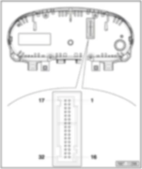
Dash panel insert -K- with control unit in dash panel insert -J285-
Connector assignment for 32-pin connector, blue -T32-
VW CADDY 2011 https://portal-diagnostov.com/license.html
https://portal-diagnostov.com/license.html Automotive Electricians Portal FZCO Automotive Electricians Portal FZCO
Получить доступ ко всем электросхемам автомобиляDownload PDF file
1 -  Fuel gauge sensor -G- (full)
2 -  Fuel gauge sensor -G- (empty)
3 -  Fuel gauge sensor 2 -G169- (full)
4 -  Fuel gauge sensor 2 -G169- (empty)
5 -  -
6 -  -
7 -  Immobiliser reader coil -D2-
8 -  Immobiliser reader coil -D2-
9 -  Output for speed signal
10 -  -
11 -  Oil level and oil temperature sender -G266-
12 -  -
13 -  -
14 -  -
15 -  -
16 -  Terminal 31
17 -  Windscreen washer fluid level sender -G33- (washer fluid level warning lamp -K37- )
18 -  Coolant shortage indicator sender -G32- (coolant temperature and coolant shortage warning lamp -K28- )
19 -  Ambient temperature sensor -G17-
20 -  Earth for sensor
21 -  -
22 -  -
23 -  -
24 -  -
25 -  Handbrake warning switch -F9- (handbrake warning lamp -K139- )
26 -  Brake fluid level warning contact -F34- (brake fluid level warning lamp -K33- )
27 -  Oil pressure switch -F1- (oil pressure warning lamp -K3- )
28 -  Data bus diagnostic interface -J533- CAN bus, high
29 -  Data bus diagnostic interface -J533- CAN bus, low
30 -  -
31 -  Terminal 15a
32 -  Terminal 30a

Back to overview → Chapter


VW CADDY 2011

Wiper motor control unit -J400- , on windscreen wiper motor -V-
Fitting location:
on left in plenum chamber.
   
VW CADDY 2011 https://portal-diagnostov.com/license.html
https://portal-diagnostov.com/license.html Automotive Electricians Portal FZCO Automotive Electricians Portal FZCO
Получить доступ ко всем электросхемам автомобиляDownload PDF file
1 -  Wiper motor control unit -J400-
A -  4-pin connector, black -T4p-

Back to overview → Chapter


VW CADDY 2011 Battery monitoring control unit J367

Battery monitoring control unit -J367-
Fitting location:
At battery negative terminal.
   
VW CADDY 2011 Battery monitoring control unit J367 https://portal-diagnostov.com/license.html
https://portal-diagnostov.com/license.html Automotive Electricians Portal FZCO Automotive Electricians Portal FZCO
Получить доступ ко всем электросхемам автомобиляDownload PDF file
1 -  Battery monitoring control unit -J367-
A -  2-pin connector -T2-

Back to overview → Chapter


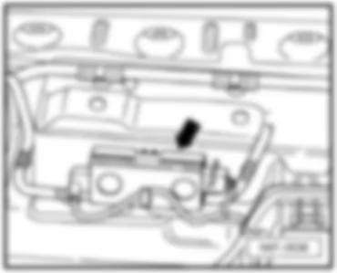
VW CADDY 2011 Control unit for cornering light and headlight range control J745

Control unit for cornering light and headlight range control -J745-
Fitting location:
Under dash panel on left.
  Note
t  The figure shows a left-hand drive vehicle.
t  On right-hand drive vehicles, theControl unit for cornering light and headlight range control -J745- on the right under the dash panel
   
VW CADDY 2011 Control unit for cornering light and headlight range control J745 https://portal-diagnostov.com/license.html
https://portal-diagnostov.com/license.html Automotive Electricians Portal FZCO Automotive Electricians Portal FZCO
Получить доступ ко всем электросхемам автомобиляDownload PDF file
1 -  Control unit for cornering light and headlight range control -J745-
A -  26-pin connector -T26b-

Back to overview → Chapter


VW CADDY 2011 Remote control receiver for auxiliary coolant heater R149

Remote control receiver for auxiliary coolant heater -R149-
Fitting location:
Under dash panel on left.
  Note
t  The figure shows a left-hand drive vehicle.
t  On right-hand drive vehicles, theRemote control receiver for auxiliary coolant heater -R149- on the right under the dash panel
   
VW CADDY 2011 Remote control receiver for auxiliary coolant heater R149 https://portal-diagnostov.com/license.html
https://portal-diagnostov.com/license.html Automotive Electricians Portal FZCO Automotive Electricians Portal FZCO
Получить доступ ко всем электросхемам автомобиляDownload PDF file
1 -  Remote control receiver for auxiliary coolant heater -R149-
A -  6-pin connector, blue -T6v-
B -  Aerial connection point

Back to overview → Chapter


VW CADDY 2011 Overview of fuse holders in engine compartment

Overview of fuse holders in engine compartment
VW CADDY 2011 Overview of fuse holders in engine compartment https://portal-diagnostov.com/license.html
https://portal-diagnostov.com/license.html Automotive Electricians Portal FZCO Automotive Electricians Portal FZCO
Получить доступ ко всем электросхемам автомобиляDownload PDF file
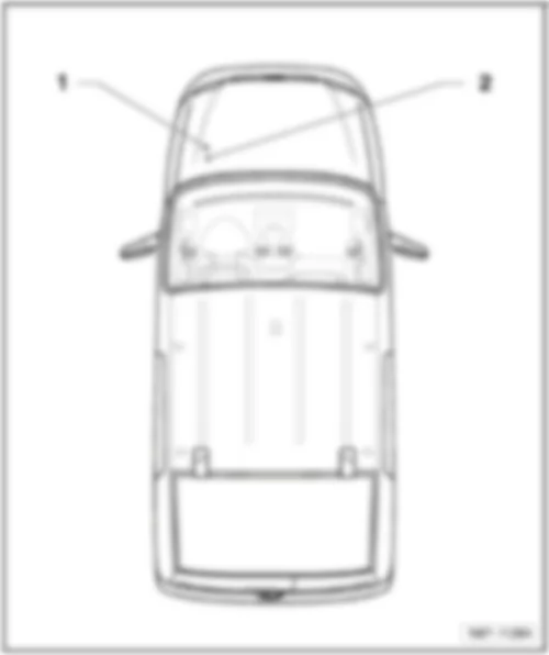
1 -  Fuses on fuse holder A -SA-
q   Fitting location → Chapter
q   Fuse assignment → Chapter
2 -  Fuses on fuse holder B -SB-
q   Fitting location → Chapter
q   Fuse assignment → Chapter

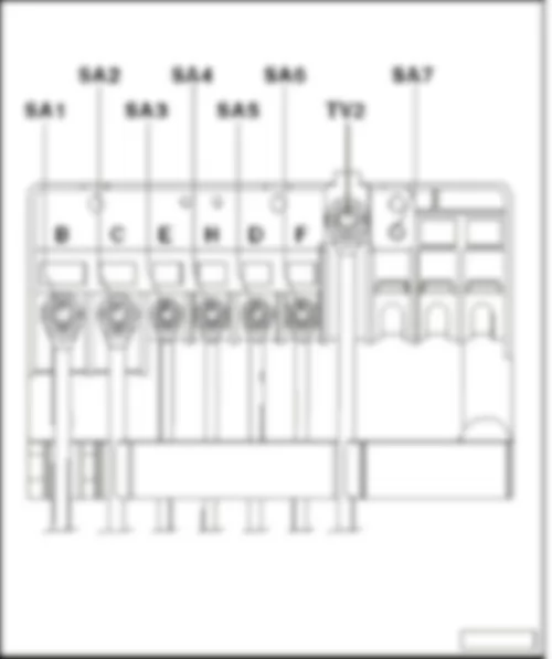
Fuses on fuse holder A -SA- on the front of the E-box, in​ engine​ compart., left, beside the battery -A-
Specified torque settings
⇒ Electrical system, Repair Group 97, Removing and installing fuse holders
Fuse colours
   
VW CADDY 2011 Overview of fuse holders in engine compartment https://portal-diagnostov.com/license.html
https://portal-diagnostov.com/license.html Automotive Electricians Portal FZCO Automotive Electricians Portal FZCO
Получить доступ ко всем электросхемам автомобиляDownload PDF file
200 A -  purple
150 A -  grey
125 A -  pink
100 A -  blue
80 A -  white
70 A -  brown
60 A -  yellow
50 A -  red
40 A -  green
30 A -  orange


VW CADDY 2011 Fuse assignment on fuse holder A SA

Fuse assignment on fuse holder A -SA-
No.   Current Flow Diagram designation Nominal value   Function/component Terminal
1 - Fuse 1 on fuse holder A -SA1- 150 A - Alternator -C- 30
    200 A - Alternator -C-1) 30
2 - Fuse 2 on fuse holder A -SA2- 80 A - Power steering control unit -J500-
Electromechanical power steering motor -V187-
30
3 - Fuse 3 on fuse holder A -SA3- 50 A - Radiator fan control unit -J293- 30
4 - Fuse 4 on fuse holder A -SA4- 80 A - X-contact relief relay -J59-
t  Fuse holder C -SC- (-SC28- up to -SC33- )
30
5 - Fuse 5 on fuse holder A -SA5- 80 A - Fuse holder C -SC- (-SC20- up to -SC24- and -SC43- up to -SC53- ) 30
6 - Fuse 6 on fuse holder A -SA6- 40 A - Low heat output relay -J359- 30
7 - Fuse 7 on fuse holder A -SA7- 80 A - High heat output relay -J360- 30

  Note
1) Models with 140 A generator only


VW CADDY 2011

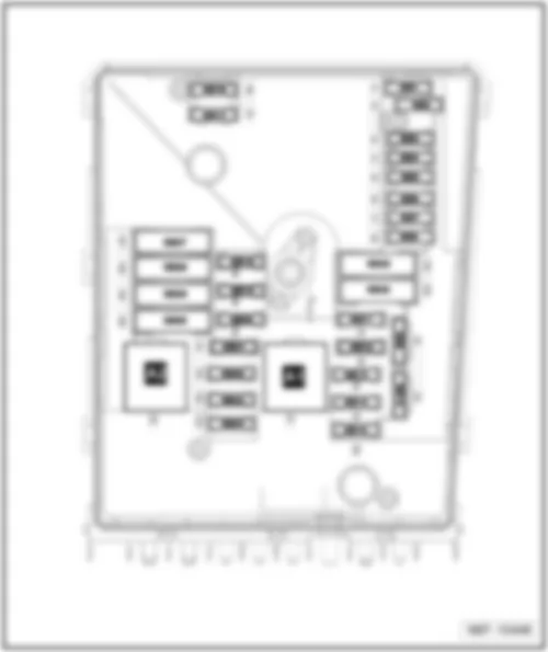
Fuses on fuse holder B -SB- on the E-box, in​ engine​ compart., left, beside the battery -A-
Fuse colours
VW CADDY 2011 https://portal-diagnostov.com/license.html
https://portal-diagnostov.com/license.html Automotive Electricians Portal FZCO Automotive Electricians Portal FZCO
Получить доступ ко всем электросхемам автомобиляDownload PDF file
40 A -  orange
30 A -  light green
25 A -  natural (white)
20 A -  yellow
15 A -  light blue
10 A -  red
7,5 A -  brown
5 A -  light brown (beige)
3 A -  purple


VW CADDY 2011 Fuse locations on fuseholder B SB

Fuse locations on fuseholder B -SB-
No.   Current Flow Diagram designation Nominal value   Function/component Terminal
1 - Fuse 1 on fuse holder B -SB1- - - - -
2 - Fuse 2 on fuse holder B -SB2- 30 A - Mechatronic unit for dual clutch gearbox -J743- 30
3 - Fuse 3 on fuse holder B -SB3- 5 A - Battery monitoring control unit -J367-
Onboard supply control unit -J519- (T52a/24)
30
4 - Fuse 4 on fuse holder B -SB4- 20 A - ABS control unit -J104-
ABS hydraulic unit -N55-
30
5 - Fuse 5 on fuse holder B -SB5- 15 A - Mechatronic unit for dual clutch gearbox -J743- 30
6 - Fuse 6 on fuse holder B -SB6- 5 A - Control unit in dash panel insert -J285-
Steering column electronics control unit -J527-
30
7 - Fuse 7 on fuse holder B -SB7- 40 A - Terminal 15 voltage supply relay -J329-
t  Fuse holder C -SC- (-SC9- up to -SC16- and -SC25- up to -SC27- )
30
8 - Fuse 8 on fuse holder B -SB8- 15 A
- Control unit with display for radio and navigation -J503-
Radio -R-
Voltage stabiliser -J532-3)
t  Control module with display unit for radio and navigation system -J503-
t  Radio -R-
t  Fuse 57 on fuse holder C -SC57-
t  Fuse 58 on fuse holder C -SC58-
30
9 - Fuse 9 on fuse holder B -SB9- 5 A - Mobile telephone operating electronics control unit -J412-4) 30
10 - Fuse 10 on fuse holder B -SB10- 5 A - Main relay -J271-
Engine control unit -J623-
Engine component current supply relay -J757-
30
11 - Fuse 11 on fuse holder B -SB11- 30 A - Auxiliary heater control unit -J364- 30
12 - Fuse 12 on fuse holder B -SB12- 5 A - Data bus diagnostic interface -J533- 30
13 - Fuse 13 on fuse holder B -SB13- 15 A - Engine control unit -J623- (petrol engine) 87a
    30 A - Engine control unit -J623- (diesel engine) 87a
14 - Fuse 14 on fuse holder B -SB14- 15 A - Fuel pressure regulating valve -N276- (diesel engine)
Fuel metering valve -N290- (diesel engine)
87a
    20 A - Ignition transformer -N152-
Ignition coil 1 with output stage -N70-
Ignition coil 2 with output stage -N127-
Ignition coil 3 with output stage -N291-
Ignition coil 4 with output stage -N292-
87a
15 - Fuse 15 on fuse holder B -SB15- 5 A - Low heat output relay -J359- (diesel engine)
High heat output relay -J360- (diesel engine)
Fuel pump relay -N17-
Electric fuel pump 2 relay -J49-
Automatic glow period control unit -J179-
87a
    10 A - Lambda probe heater -Z19-
Lambda probe 1 heater after catalytic converter -Z29-
Low heat output relay -J359-
High heat output relay -J360-
Fuel pump switch-off relay -J333-2)
Gas injection valve 1 -N366-1)
Gas injection valve 2 -N367-1)
Gas injection valve 3 -N368-1)
Gas injection valve 4 -N369-1)
87a
    15 A - High-pressure valve for gas mode -N372-2)
Valve for gas tank -N495-2)
Sensor for gas level gauge -G707-2)
Gas injection valve 1 -N366-2)
Gas injection valve 2 -N367-2)
Gas injection valve 3 -N368-2)
Gas injection valve 4 -N369-2)
87a
16 - Fuse 16 on fuse holder B -SB16- 30 A - Onboard supply control unit -J519- (T52c/42)
t  Light bulb for right foglamp -L23-
t  Right cornering light bulb -L149-
t  Rear left fog light bulb -L46- , or rear right fog light bulb -L47-
t  Right daytime running light bulb -L175-
t  Left side light bulb -M1-
t  Right tail light bulb -M2-
t  Rear left turn signal bulb -M6-
t  Front right turn signal bulb -M7-
t  Left brake light bulb -M9-
t  Right reversing light bulb -M17-
t  Left turn signal repeater bulb -M18-
t  High-mounted brake light bulb -M25-
t  Right headlight dipped beam bulb -M31-
t  Right headlight main beam bulb -M32-
30
17 - Fuse 17 on fuse holder B -SB17- 15 A - Horn relay -J413- 30
18 - Fuse 18 on fuse holder B -SB18- 30 A - Special vehicle control unit -J608- 30
19 - Fuse 19 on fuse holder B -SB19- 30 A - Wiper motor control unit -J400- 30
20 - Fuse 20 on fuse holder B -SB20- 10 A - Fuel tank shut-off valve 1 -N361-1)
Fuel tank shut-off valve 2 -N362-1)
Fuel tank shut-off valve 3 -N363-1)
Fuel tank shut-off valve 4 -N429-1)
Fuel tank shut-off valve 5 -N430-1)
Coolant circulation pump -V50-
87a
21 - Fuse 21 on fuse holder B -SB21- 10 A - Lambda probe heater -Z19- (diesel engine) 87a
    15 A - Fuel pump control unit -J538-
Lambda probe heater -Z19-
Lambda probe 1 heater after catalytic converter -Z29-
87a
22 - Fuse 22 on fuse holder B -SB22- 5 A - Clutch position sender -G476-
Brake light switch -F-5)
87a
23 - Fuse 23 on fuse holder B -SB23- 5 A - Additional coolant pump relay -J496- 87a
    10 A - Air mass meter -G70- (Diesel engine)
Charge pressure control solenoid valve -N75- (Diesel engine)
Exhaust gas recirculation cooler changeover valve -N345- (Diesel engine)
Control unit for gas mode -J659-
Relay for gas shut-off valves -J908-1)
High-pressure valve for gas mode -N372-1)
87a
    15 A - Fuel pressure regulating valve -N276- 87a
24 - Fuse 24 on fuse holder B -SB24- 10 A - Radiator fan control unit -J293-
Secondary air pump relay -J299-
Additional coolant pump relay -J496-
Activated charcoal filter solenoid valve 1 -N80-
Coolant regulating valve -N515-
Variable intake manifold changeover valve -N156-
Coolant circulation pump 2 -V178-
Injector, cylinder 1 -N30-1)
Injector, cylinder 2 -N31-1)
Injector, cylinder 3 -N32-1)
Injector, cylinder 4 -N33-1)
87a
25 - Fuse 25 on fuse holder B -SB25- 40 A - ABS hydraulic pump -V64-
ABS control unit -J104-
30
26 - Fuse 26 on fuse holder B -SB26- 30 A - Onboard supply control unit -J519- (T52a/1)
t  Left cornering light bulb -L148-
t  Left fog light bulb -L22-
t  Rear left fog light bulb -L46- , or rear right fog light bulb -L47-
t  Left daytime running light bulb -L174-
t  Right side light bulb -M3-
t  Left tail light bulb -M4-
t  Front left turn signal bulb -M5-
t  Rear right turn signal bulb -M8-
t  Right brake light bulb -M10-
t  Left reversing light bulb -M16-
t  Right turn signal repeater bulb -M19-
t  Left headlight dipped beam bulb -M29-
t  Left headlight main beam bulb -M30-
30
27 - Fuse 27 on fuse holder B -SB27- 40 A - Secondary air pump motor -V101- 30
    50 A - Automatic glow period control unit -J179- 30
28 - Fuse 28 on fuse holder B -SB28- - - - -
29 - Fuse 29 on fuse holder B -SB29- 30 A - Fuse 18 on fuse holder C -SC18-
Fuse 19 on fuse holder C -SC19-
30
    50 A - Fuse 35 on fuse holder C -SC35-
Fuse 39 on fuse holder C -SC39-
Fuse 54 on fuse holder C -SC54-
Fuse 55 on fuse holder C -SC55-
Fuse 59 on fuse holder C -SC59-
Fuse 60 on fuse holder C -SC60-
30
30 - Fuse 30 on fuse holder B -SB30- 50 A - Fuse holder C -SC- (-SC40- up to -SC42- ) 30

t  1) for vehicles with engine code BSX only
t  2) for vehicles with engine code CHGA only
t  3) for vehicles with start/stop system only
t  4) for vehicles without start/stop system only
t  5) effective since November 2011