AUTOMOTIVE ELECTRICIANS PORTAL

VW CADDY 2013 – Data bus network . Wiring diagrams, Pin Connector, Location

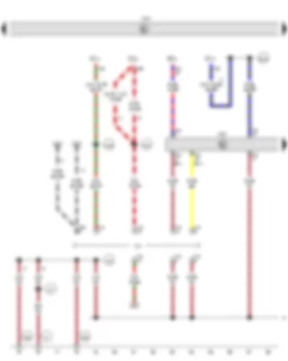
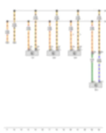
Wiring Diagram VW CADDY 2013 - Interior monitoring sensor - Vehicle inclination sender - Rain and light sensor - Anti-theft alarm sensor - Alarm horn - Wiper motor control unit - Onboard supply control unit


Wiring Diagram  VW CADDY 2013 - Interior monitoring sensor - Vehicle inclination sender - Rain and light sensor - Anti-theft alarm sensor - Alarm horn - Wiper motor control unit - Onboard supply control unit https://portal-diagnostov.com/license.html
https://portal-diagnostov.com/license.html Automotive Electricians Portal FZCO Automotive Electricians Portal FZCO
Download PDF file
G273 Interior monitoring sensor
G384 Vehicle inclination sender
G397 Rain and light sensor
G578 Anti-theft alarm sensor
H12 Alarm horn
J400 Wiper motor control unit
J519 Onboard supply control unit
T3f 3-pin connector, black
T3w 3-pin connector
T4p 4-pin connector
T4z 4-pin connector, black
T52b 52-pin connector, white
V Windscreen wiper motor
  B528 Connection 1 (LIN bus) in main wiring harness
  B549 Connection 2 (LIN bus) in main wiring harness
*Only left-hand drive models
*2Only right-hand drive models
*3Only models with no interior monitor
*4Only models with interior monitor
*5Only models with no rain and light sensor
*6Up to April 2011
*7Only models with rain and light sensor
*8From May 2011

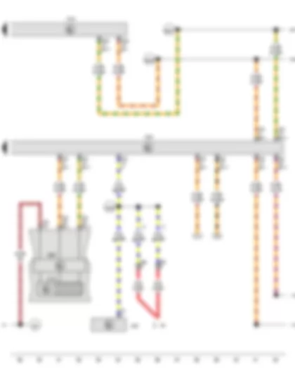
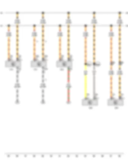
Wiring Diagram VW CADDY 2013 - Onboard supply control unit - Data bus diagnostic interface - Diagnostic connection


Wiring Diagram  VW CADDY 2013 - Onboard supply control unit - Data bus diagnostic interface - Diagnostic connection https://portal-diagnostov.com/license.html
https://portal-diagnostov.com/license.html Automotive Electricians Portal FZCO Automotive Electricians Portal FZCO
すべての配線図にアクセスする車Download PDF file
J519 Onboard supply control unit
J533 Data bus diagnostic interface
SC10 Fuse 10 on fuse holder C
SB12 Fuse 12 on fuse holder B
SC14 Fuse 14 on fuse holder C
SC21 Fuse 21 on fuse holder C
T16 16-pin connector
T20 20-pin connector, red
T40 40-pin connector
U31 Diagnostic connection
  47 Earth point, in front right footwell
  367 Earth connection 2, in main wiring harness
  375 Earth connection 10, in main wiring harness
  377 Earth connection 12, in main wiring harness
  602 Earth point, in front left footwell
  605 Earth point, on top end of steering column
  A167 Positive connection 3 (30a) in dash panel wiring harness
  A192 Positive connection 3 (15a) in dash panel wiring harness
  B135 Connection 1 (15a), in interior wiring harness
*From May 2011
*2Only left-hand drive models
*3From November 2012
*4Only models with dual clutch gearbox 0AM
*5Only models with dual clutch gearbox 02E
*6Only right-hand drive models

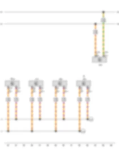
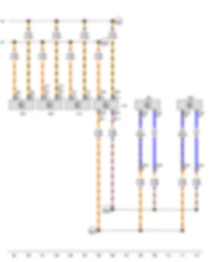
Wiring Diagram VW CADDY 2013 - Alternator - Multifunction indicator - Control unit in dash panel insert - Battery monitor control unit - Onboard supply control unit - Data bus diagnostic interface


Wiring Diagram  VW CADDY 2013 - Alternator - Multifunction indicator - Control unit in dash panel insert - Battery monitor control unit - Onboard supply control unit - Data bus diagnostic interface https://portal-diagnostov.com/license.html
https://portal-diagnostov.com/license.html Automotive Electricians Portal FZCO Automotive Electricians Portal FZCO
すべての配線図にアクセスする車Download PDF file
C Alternator
J119 Multifunction indicator
J285 Control unit in dash panel insert
J367 Battery monitor control unit
J519 Onboard supply control unit
J533 Data bus diagnostic interface
T2 2-pin connector
T2c 2-pin connector, near starter
T4t 4-pin connector, near starter
T20 20-pin connector, red
T32 32-pin connector, blue
T52c 52-pin connector, brown
  367 Earth connection 2, in main wiring harness
  A178 Connection (infotainment CAN bus, high), in dash panel wiring harness
  A179 Connection (infotainment CAN bus, low), in dash panel wiring harness
  A209 Connection 1 (LIN bus) in dash panel wiring harness
  B397 Connection 1 (convenience CAN bus, high), in main wiring harness
  B406 Connection 1 (convenience CAN bus, low), in main wiring harness
*Only models with start/stop system
*2Only models with no air conditioning system
*3Only models with air conditioning system

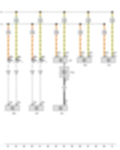
Wiring Diagram VW CADDY 2013 - Trailer detector control unit - Auxiliary heater control unit - Mobile telephone operating electronics control unit - Control unit with display for radio and navigation - Radio - Interface for external multimedia unit


Wiring Diagram  VW CADDY 2013 - Trailer detector control unit - Auxiliary heater control unit - Mobile telephone operating electronics control unit - Control unit with display for radio and navigation - Radio - Interface for external multimedia unit https://portal-diagnostov.com/license.html
https://portal-diagnostov.com/license.html Automotive Electricians Portal FZCO Automotive Electricians Portal FZCO
すべての配線図にアクセスする車Download PDF file
J345 Trailer detector control unit
J364 Auxiliary heater control unit
J412 Mobile telephone operating electronics control unit
J503 Control unit with display for radio and navigation
R Radio
R215 Interface for external multimedia unit
T8 8-pin connector
T8f 8-pin connector
T12m 12-pin connector
T12n 12-pin connector, black
T54 54-pin connector
  A178 Connection (infotainment CAN bus, high), in dash panel wiring harness
  A179 Connection (infotainment CAN bus, low), in dash panel wiring harness
  B397 Connection 1 (convenience CAN bus, high), in main wiring harness
  B406 Connection 1 (convenience CAN bus, low), in main wiring harness

Wiring Diagram VW CADDY 2013 - Climatronic control unit - Air conditioning system control unit - Driver door control unit - Front passenger door control unit - Multifunction steering wheel control unit - Steering column electronics control unit


Wiring Diagram  VW CADDY 2013 - Climatronic control unit - Air conditioning system control unit - Driver door control unit - Front passenger door control unit - Multifunction steering wheel control unit - Steering column electronics control unit https://portal-diagnostov.com/license.html
https://portal-diagnostov.com/license.html Automotive Electricians Portal FZCO Automotive Electricians Portal FZCO
すべての配線図にアクセスする車Download PDF file
F350 Coil connector
J255 Climatronic control unit
J301 Air conditioning system control unit
J386 Driver door control unit
J387 Front passenger door control unit
J453 Multifunction steering wheel control unit, in steering wheel
J527 Steering column electronics control unit
T5u 5-pin connector
T12e 12-pin connector
T16a 16-pin connector
T20a 20-pin connector
T20b 20-pin connector
T20c 20-pin connector
T28a 28-pin connector, in left A-pillar coupling station
T28b 28-pin connector, in right A-pillar coupling station
  B397 Connection 1 (convenience CAN bus, high), in main wiring harness
  B406 Connection 1 (convenience CAN bus, low), in main wiring harness
*Only left-hand drive models
*2Only right-hand drive models

Wiring Diagram VW CADDY 2013 - Selector lever - Parking aid control unit - Park assist steering control unit


Wiring Diagram  VW CADDY 2013 - Selector lever - Parking aid control unit - Park assist steering control unit https://portal-diagnostov.com/license.html
https://portal-diagnostov.com/license.html Automotive Electricians Portal FZCO Automotive Electricians Portal FZCO
すべての配線図にアクセスする車Download PDF file
E313 Selector lever
J446 Parking aid control unit
J791 Park assist steering control unit
T10u 10-pin connector, under selector lever
T16b 16-pin connector, brown
T16k 16-pin connector, brown
T16l 16-pin connector, brown
  B383 Connection 1 (powertrain CAN bus, high), in main wiring harness
  B390 Connection 1 (powertrain CAN bus, low), in main wiring harness
*From May 2012
*2Up to April 2012

Wiring Diagram VW CADDY 2013 - Airbag control unit - All-wheel drive control unit - Power steering control unit - Mechatronic unit for dual clutch gearbox


Wiring Diagram  VW CADDY 2013 - Airbag control unit - All-wheel drive control unit - Power steering control unit - Mechatronic unit for dual clutch gearbox https://portal-diagnostov.com/license.html
https://portal-diagnostov.com/license.html Automotive Electricians Portal FZCO Automotive Electricians Portal FZCO
すべての配線図にアクセスする車Download PDF file
J234 Airbag control unit
J492 All-wheel drive control unit
J500 Power steering control unit
J743 Mechatronic unit for dual clutch gearbox
T3o 3-pin connector
T6z 6-pin connector, near left headlight
T8b 8-pin connector, black
T20e 20-pin connector
T25 25-pin connector
T50 50-pin connector
  B383 Connection 1 (powertrain CAN bus, high), in main wiring harness
  B384 Connection 2 (powertrain CAN bus, high), in main wiring harness
  B390 Connection 1 (powertrain CAN bus, low), in main wiring harness
  B391 Connection 2 (powertrain CAN bus, low), in main wiring harness
*Only models with dual clutch gearbox 0AM
*2Only models with dual clutch gearbox 02E

Wiring Diagram VW CADDY 2013 - ABS control unit - Engine control unit - Output module for left headlight - Output module for right headlight - Control unit for cornering light and headlight range control


Wiring Diagram  VW CADDY 2013 - ABS control unit - Engine control unit - Output module for left headlight - Output module for right headlight - Control unit for cornering light and headlight range control https://portal-diagnostov.com/license.html
https://portal-diagnostov.com/license.html Automotive Electricians Portal FZCO Automotive Electricians Portal FZCO
すべての配線図にアクセスする車Download PDF file
J104 ABS control unit
J623 Engine control unit
J667 Output module for left headlight, on left headlight
J668 Output module for right headlight, on right headlight
J745 Control unit for cornering light and headlight range control
T14b 14-pin connector, on left headlight, black
T14c 14-pin connector, on right headlight, black
T26b 26-pin connector
T32d 32-pin connector
T32e 32-pin connector
T47 47-pin connector
T94 94-pin connector
T121 121-pin connector
  B229 Connection (high bus), in interior wiring harness
  B230 Connection (low bus), in interior wiring harness
  B383 Connection 1 (powertrain CAN bus, high), in main wiring harness
  B390 Connection 1 (powertrain CAN bus, low), in main wiring harness


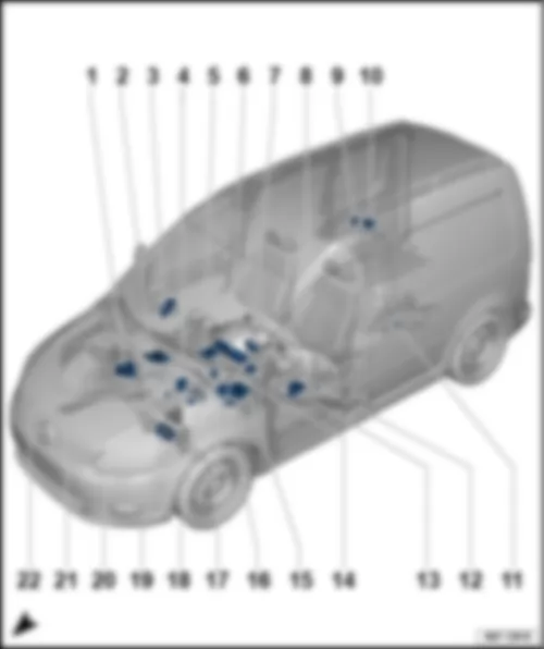
VW CADDY 2013 Overview of all control units

Overview of all control units
VW CADDY 2013 Overview of all control units https://portal-diagnostov.com/license.html
https://portal-diagnostov.com/license.html Automotive Electricians Portal FZCO Automotive Electricians Portal FZCO
すべての配線図にアクセスする車Download PDF file
1 -  ABS control unit -J104-
q   Connector assignment
2 -  Engine control unit -J623-
q   Connector assignment for 121-pin connector -T121-
q   Connector assignment for 60-pin connector -T60- and 94-pin connector -T94-
3 -  Front passenger door control unit -J387-
q   Connector assignment
4 -  Control unit for cornering light and headlight range control -J745-
5 -  Mobile telephone operating electronics control unit -J412-
q   Connector assignment
6 -  Control unit in dash panel insert -J285-
7 -  Steering column electronics control unit -J527-
q   Connector assignment
8 -  Data bus diagnostic interface -J533-
q   Connector assignment
9 -  Trailer detector control unit -J345-
q   Connector assignment
10 -  Parking aid control unit -J446- (2JB )
11 -  All-wheel drive control unit -J492-
12 -  Heated front seats control unit -J774-
13 -  Driver door control unit -J386-
q   Connector assignment
14 -  Remote control receiver for auxiliary coolant heater -R149-
15 -  Onboard supply control unit -J519-
q   Connector assignment of 52-pin connector -T52a- black
q   Connector assignment of 52-pin connector -T52b- white
q   Connector assignment of 52-pin connector -T52c- brown
16 -  Park assist steering control unit -J791- (7X5 ),Parking aid control unit -J446- (2JG, 2JX )
q   Connector assignment
17 -  Voltage stabiliser -J532-
18 -  Special vehicle control unit -J608-
19 -  Power steering control unit -J500-
q   Connector assignment
20 -  Airbag control unit -J234-
q   Connector assignment
21 -  Battery monitoring control unit -J367-
22 -  Wiper motor control unit -J400-


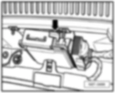
VW CADDY 2013 Engine control unit J623

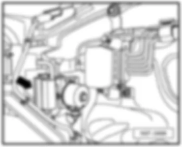
Fitting location:
under plenum chamber cover, centre -arrow-
 
VW CADDY 2013 Engine control unit J623 https://portal-diagnostov.com/license.html
https://portal-diagnostov.com/license.html Automotive Electricians Portal FZCO Automotive Electricians Portal FZCO
すべての配線図にアクセスする車Download PDF file
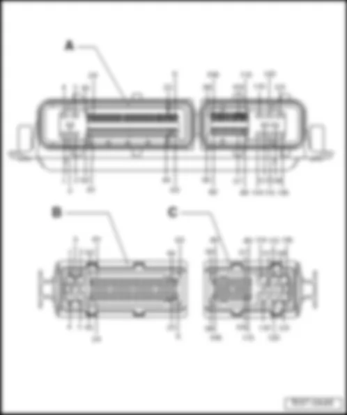
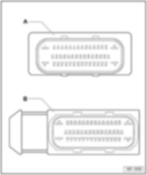
121-pin connector assignment:
VW CADDY 2013 Engine control unit J623 https://portal-diagnostov.com/license.html
https://portal-diagnostov.com/license.html Automotive Electricians Portal FZCO Automotive Electricians Portal FZCO
すべての配線図にアクセスする車Download PDF file
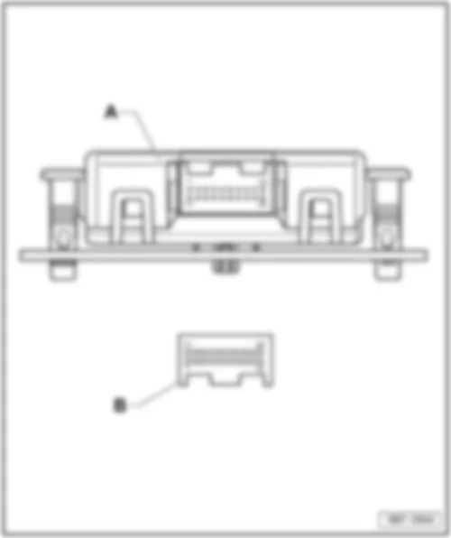
A -  Engine control unit -J623-
Connector:
B -  81-pin connector -T81- (Pin 1 - Pin 81)
C -  40-pin connector -T40- (Pin 82 - Pin 121)
  Note
The 40-pin connector -T40- and the 81-pin connector -T81- are represented in the wiring diagram as a 121-pin connector -T121- .
   
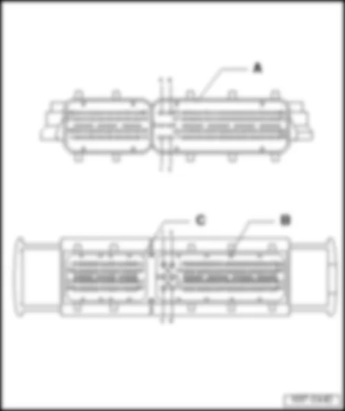
154-pin connector assignment:
VW CADDY 2013 Engine control unit J623 https://portal-diagnostov.com/license.html
https://portal-diagnostov.com/license.html Automotive Electricians Portal FZCO Automotive Electricians Portal FZCO
すべての配線図にアクセスする車Download PDF file
A -  Engine control unit -J623-
Connector:
B -  94-pin connector -T94-

Back to overview
Power steering control unit -J500-
   
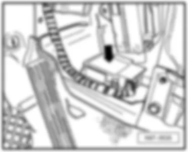
Fitting location:
On steering on centre of assembly carrier -arrow-
 
VW CADDY 2013 Engine control unit J623 https://portal-diagnostov.com/license.html
https://portal-diagnostov.com/license.html Automotive Electricians Portal FZCO Automotive Electricians Portal FZCO
すべての配線図にアクセスする車Download PDF file
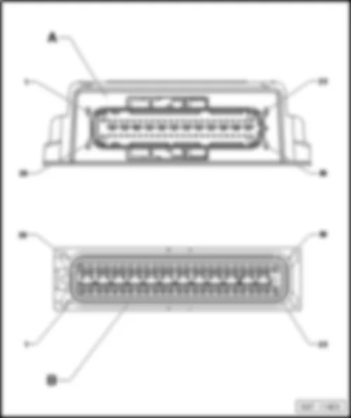
Connector assignment:
VW CADDY 2013 Engine control unit J623 https://portal-diagnostov.com/license.html
https://portal-diagnostov.com/license.html Automotive Electricians Portal FZCO Automotive Electricians Portal FZCO
すべての配線図にアクセスする車Download PDF file
A -  Power steering control unit -J500-
Connector:
B -  2-pin connector -T2b-
D -  5-pin connector -T5s-

Back to overview


VW CADDY 2013 ABS control unit J104

Fitting location:
On bulkhead, in​ engine​ compart., right​ -arrow-
 
VW CADDY 2013 ABS control unit J104 https://portal-diagnostov.com/license.html
https://portal-diagnostov.com/license.html Automotive Electricians Portal FZCO Automotive Electricians Portal FZCO
すべての配線図にアクセスする車Download PDF file
Connector assignment:
VW CADDY 2013 ABS control unit J104 https://portal-diagnostov.com/license.html
https://portal-diagnostov.com/license.html Automotive Electricians Portal FZCO Automotive Electricians Portal FZCO
すべての配線図にアクセスする車Download PDF file
A -  ABS control unit -J104-
q   with ESP only
Connector:
B -  47-pin connector, on wiring harness (T47)

Back to overview


VW CADDY 2013 Airbag control unit J234

Fitting location:
Under centre console -arrow-
 
VW CADDY 2013 Airbag control unit J234 https://portal-diagnostov.com/license.html
https://portal-diagnostov.com/license.html Automotive Electricians Portal FZCO Automotive Electricians Portal FZCO
すべての配線図にアクセスする車Download PDF file
Connector assignment:
VW CADDY 2013 Airbag control unit J234 https://portal-diagnostov.com/license.html
https://portal-diagnostov.com/license.html Automotive Electricians Portal FZCO Automotive Electricians Portal FZCO
すべての配線図にアクセスする車Download PDF file
A -  Airbag control unit -J234-
Connector:
B -  50-pin connector -T50-

Back to overview


VW CADDY 2013 Front passenger door control unit J387

Fitting location:
On door inner part on front right -arrow-
  Note
Illustration shows left side. The right side is similar.
 
VW CADDY 2013 Front passenger door control unit J387 https://portal-diagnostov.com/license.html
https://portal-diagnostov.com/license.html Automotive Electricians Portal FZCO Automotive Electricians Portal FZCO
すべての配線図にアクセスする車Download PDF file
Connector assignment:
VW CADDY 2013 Front passenger door control unit J387 https://portal-diagnostov.com/license.html
https://portal-diagnostov.com/license.html Automotive Electricians Portal FZCO Automotive Electricians Portal FZCO
すべての配線図にアクセスする車Download PDF file
A -  Front passenger door control unit -J387-
Connector:
B -  32-pin connector -T32a-
D -  20-pin connector -T20b-

Back to overview


VW CADDY 2013 Mobile telephone operating electronics control unit J412

Mobile telephone operating electronics control unit -J412-
Fitting location:
Under seat on front right -arrow -
 
VW CADDY 2013 Mobile telephone operating electronics control unit J412 https://portal-diagnostov.com/license.html
https://portal-diagnostov.com/license.html Automotive Electricians Portal FZCO Automotive Electricians Portal FZCO
すべての配線図にアクセスする車Download PDF file
Connector assignment
VW CADDY 2013 Mobile telephone operating electronics control unit J412 https://portal-diagnostov.com/license.html
https://portal-diagnostov.com/license.html Automotive Electricians Portal FZCO Automotive Electricians Portal FZCO
すべての配線図にアクセスする車Download PDF file
A -  Mobile telephone operating electronics control unit -J412-
Connector:
B -  54-pin connector -T54-

Back to overview


VW CADDY 2013 Special vehicle control unit J608

Special vehicle control unit -J608-
Fitting location:
Above the Airbag control unit -arrow-
Back to overview
 
VW CADDY 2013 Special vehicle control unit J608 https://portal-diagnostov.com/license.html
https://portal-diagnostov.com/license.html Automotive Electricians Portal FZCO Automotive Electricians Portal FZCO
すべての配線図にアクセスする車Download PDF file


VW CADDY 2013 Trailer detector control unit J345

Trailer detector control unit -J345-
Fitting location:
In rear right side panel -arrow-
 
VW CADDY 2013 Trailer detector control unit J345 https://portal-diagnostov.com/license.html
https://portal-diagnostov.com/license.html Automotive Electricians Portal FZCO Automotive Electricians Portal FZCO
すべての配線図にアクセスする車Download PDF file
Connector assignment:
VW CADDY 2013 Trailer detector control unit J345 https://portal-diagnostov.com/license.html
https://portal-diagnostov.com/license.html Automotive Electricians Portal FZCO Automotive Electricians Portal FZCO
すべての配線図にアクセスする車Download PDF file
A -  Trailer detector control unit -J345-
Connector:
B -  16-pin connector -T16x-

Back to overview


VW CADDY 2013 Heated front seats control unit J774

Heated front seats control unit -J774-
Fitting location:
on front left of seat frame -arrow-
Back to overview


VW CADDY 2013 Steering column electronics control unit J527

Steering column electronics control unit -J527-
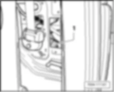
Fitting location:
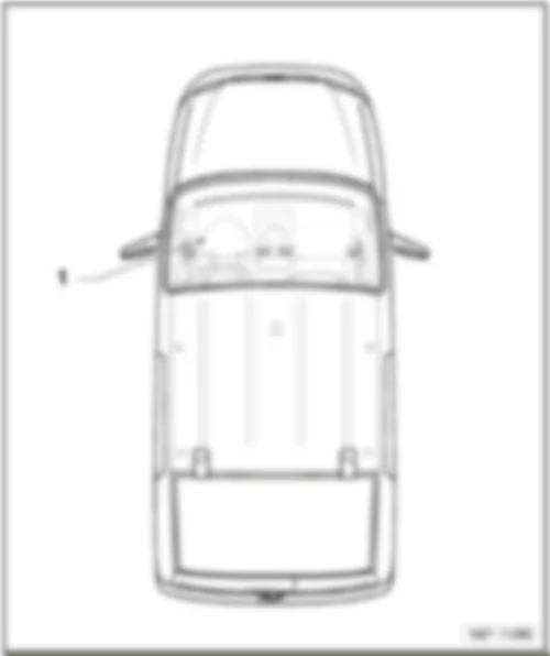
under steering column, near steering column switch -1-
 
VW CADDY 2013 Steering column electronics control unit J527 https://portal-diagnostov.com/license.html
https://portal-diagnostov.com/license.html Automotive Electricians Portal FZCO Automotive Electricians Portal FZCO
すべての配線図にアクセスする車Download PDF file
Connector assignment
VW CADDY 2013 Steering column electronics control unit J527 https://portal-diagnostov.com/license.html
https://portal-diagnostov.com/license.html Automotive Electricians Portal FZCO Automotive Electricians Portal FZCO
すべての配線図にアクセスする車Download PDF file
1 -  Steering column electronics control unit -J527-
q   under steering column, near steering column switch

   
Connector assignment:
VW CADDY 2013 Steering column electronics control unit J527 https://portal-diagnostov.com/license.html
https://portal-diagnostov.com/license.html Automotive Electricians Portal FZCO Automotive Electricians Portal FZCO
すべての配線図にアクセスする車Download PDF file
A -  16-pin connector -T16a-
1 - Airbag 1 -
2 - Airbag 1 +
3 - Not assigned
4 - Not assigned

Back to overview


VW CADDY 2013 Parking aid control unit J446

Parking aid control unit -J446-
Fitting location:
behind rear right side trim -arrow-
Back to overview
 
VW CADDY 2013 Parking aid control unit J446 https://portal-diagnostov.com/license.html
https://portal-diagnostov.com/license.html Automotive Electricians Portal FZCO Automotive Electricians Portal FZCO
すべての配線図にアクセスする車Download PDF file


VW CADDY 2013 All-wheel drive control unit J492

All-wheel drive control unit -J492-
Fitting location:
On rear final drive -arrow-
Back to overview
 
VW CADDY 2013 All-wheel drive control unit J492 https://portal-diagnostov.com/license.html
https://portal-diagnostov.com/license.html Automotive Electricians Portal FZCO Automotive Electricians Portal FZCO
すべての配線図にアクセスする車Download PDF file


VW CADDY 2013 Driver door control unit J386

Driver door control unit -J386-
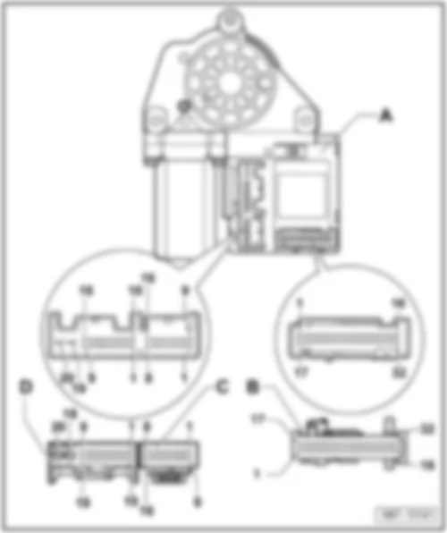
Fitting location:
On door inner part on front left -arrow-
 
VW CADDY 2013 Driver door control unit J386 https://portal-diagnostov.com/license.html
https://portal-diagnostov.com/license.html Automotive Electricians Portal FZCO Automotive Electricians Portal FZCO
すべての配線図にアクセスする車Download PDF file
Connector assignment:
VW CADDY 2013 Driver door control unit J386 https://portal-diagnostov.com/license.html
https://portal-diagnostov.com/license.html Automotive Electricians Portal FZCO Automotive Electricians Portal FZCO
すべての配線図にアクセスする車Download PDF file
A -  Driver door control unit -J386-
Connector:
B -  32-pin connector -T32b- (only vehicles with window regulator)
C -  16-pin connector -T16f-

Back to overview


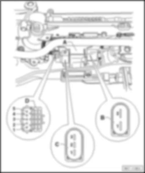
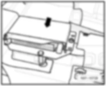
VW CADDY 2013 Onboard supply control unit J519

Onboard supply control unit -J519-
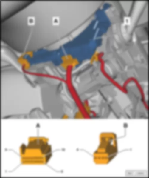
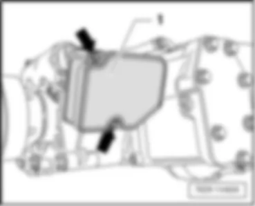
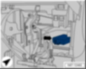
Fitting location:
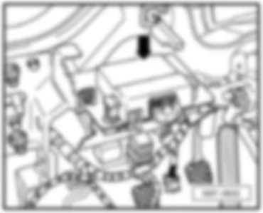
Below the left dash panel, between the relay carriers-D-
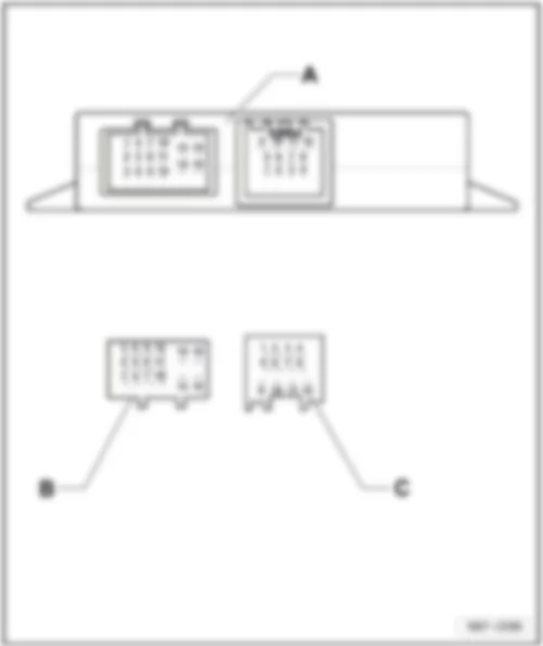
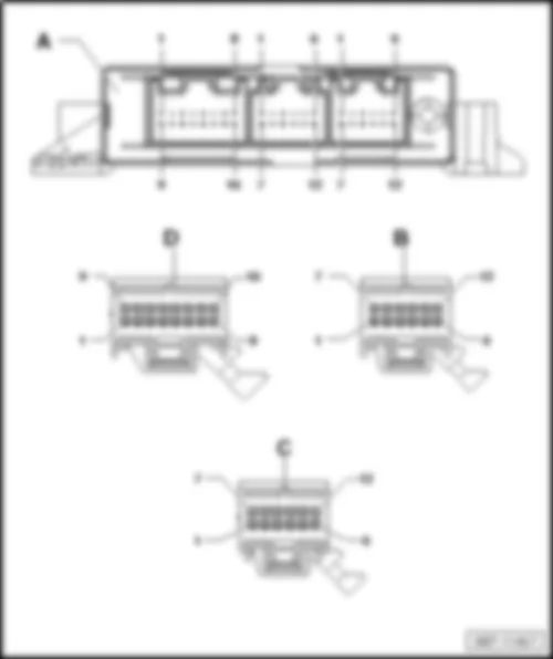
Connector assignment, 52-pin connector, black -T52a-
Connector assignment, 52-pin connector, white -T52b-
Connector assignment, 52-pin connector, brown -T52c-
   
VW CADDY 2013 Onboard supply control unit J519 https://portal-diagnostov.com/license.html
https://portal-diagnostov.com/license.html Automotive Electricians Portal FZCO Automotive Electricians Portal FZCO
すべての配線図にアクセスする車Download PDF file

VW CADDY 2013 Onboard supply control unit J519 https://portal-diagnostov.com/license.html
https://portal-diagnostov.com/license.html Automotive Electricians Portal FZCO Automotive Electricians Portal FZCO
すべての配線図にアクセスする車Download PDF file
1 -  Fuse 26 on fuse holder B -SB26- (Terminal 30a)
t  Onboard supply control unit -J519-
t  Left fog light bulb -L22- , or left cornering light bulb -L148-
t  Rear left fog light bulb -L46- , or rear right fog light bulb -L47-
t  Left daytime running light bulb -L174-
t  Right side light bulb -M3-
t  Left tail light bulb -M4-
t  Front left turn signal bulb -M5-
t  Rear right turn signal bulb -M8-
t  Right brake light bulb -M10-
t  Left reversing light bulb -M16-
t  Right turn signal repeater bulb -M19-
t  Left headlight dipped beam bulb -M29-
t  Left headlight main beam bulb -M30-
2 -  -
3 -  Right turn signal repeater bulb -M19-
4 -  Left turn signal repeater bulb -M18-
5 -  Left headlight main beam bulb -M30-
6 -  Left daytime running light bulb -L174- (2-filament light bulb)
7 -  -
8 -  -
9 -  Rear right turn signal bulb -M8-
10 -  Front left turn signal bulb -M5-
11 -  Left headlight dipped beam bulb -M29-
12 -  Connection (door contact switch), in rear wiring harness -W22- , luggage compartment light switch -F5- , rear lid lock unit -F256- , luggage compartment light -W3-
13 -  Rear lid handle release button -E234-
14 -  Bonnet contact switch -F266-
15 -  Rear right central locking lock unit -F223-
16 -  Reversing light switch -F4-
17 -  Rear fog light switch -E18-
18 -  Light switch -E1- (Daytime running light)
19 -  Light switch -E1- (Side lights)
20 -  Light switch -E1- (Driving light assist)
21 -  Fog light switch -E7-
22 -  Light switch -E1- (Headlight dipped beam)
23 -  Earth connection -31-
24 -  Fuse 3 on fuse holder B -SB3- (terminal 30_ref)
25 -  Left fog light bulb -L22- , left cornering light bulb -L148-
26 -  Right brake light bulb -M10-
27 -  Left tail light bulb -M4- (2-filament light bulb)
28 -  Left reversing light bulb -M16-
29 -  Contact switch for rear left door -F227- , rear lid lock unit -F256-
30 -  Rear right door contact switch -F11-
31 -  -
32 -  Rear left interior locking button -E310-
33 -  Interior illumination switch -E599- , Rear left door lock unit -VX23- , Surround lighting 1 in rear lid -W61- , Surround lighting 2 in rear lid -W62-
34 -  Rear left central locking lock unit -F222-
35 -  Heater/heat output switch -E16-
36 -  Interior monitoring deactivation switch -E267-
37 -  -
38 -  Rear left central locking lock unit -F222-
39 -  -
40 -  Rear right central locking lock unit -F223-
41 -  Rear left door contact switch -F10-
42 -  Earth connection -31-
43 -  Washer pump -V5- , Rear window wiper motor -V12- , windscreen and rear window washer pump -V59-
44 -  Right side light bulb -M3- (2-filament light bulb)
45 -  High-mounted brake light bulb -M25-
46 -  Rear lid release motor -V139-
47 -  -
48 -  Left sliding door central locking motor -V95-
49 -  Right sliding door central locking motor -V58-
50 -  -
51 -  -
52 -  -

Back to overview
   
52-pin connector -T52b- white-B-
VW CADDY 2013 Onboard supply control unit J519 https://portal-diagnostov.com/license.html
https://portal-diagnostov.com/license.html Automotive Electricians Portal FZCO Automotive Electricians Portal FZCO
すべての配線図にアクセスする車Download PDF file
1 -  Fuse 50 on fuse holder C -SC50- (terminal 30_ZV)
2 -  Washer pump -V5- , Rear window wiper motor -V12- , windscreen and rear window washer pump -V59-
3 -  -
4 -  -
5 -  Rear left door lock unit -VX23-
6 -  -
7 -  Left sliding door central locking motor -V95-
8 -  Right sliding door central locking motor -V58-
9 -  -
10 -  -
11 -  Rear lid release motor -V139-
12 -  Terminal 15 voltage supply relay -J329-
13 -  -
14 -  Heater/heat output switch -E16-
15 -  Switch and instrument illumination regulator -E20-
16 -  Rear left interior locking button -E310-
17 -  -
18 -  -
19 -  -
20 -  -
21 -  Heated front seats control unit -J774-
22 -  Heated rear window relay -J9-
23 -  -
24 -  Indicator lamp for hazard warning light -K6-
25 -  -
26 -  -
27 -  -
28 -  X-contact relief relay -J59-
29 -  Engine control unit -J623- , terminal 50 voltage supply relay -J682-
30 -  Switch and instrument illumination regulator -E20-
31 -  -
32 -  -
33 -  Wiper motor control unit -J400- , rain and light sensor -G397- (LIN bus)
34 -  -
35 -  -
36 -  Alarm horn -H12- , interior monitoring sensor -G273- , vehicle inclination sender -G384- , Anti-theft alarm sensor -G578- (LIN bus)
37 -  Interior monitoring deactivation switch -E267-
38 -  Fuel pump relay -J17-Fuel supply relay -J643-
39 -  -
40 -  Headlight washer system relay -J39-
41 -  Horn relay -J413-
42 -  Fuse 46 on fuse holder C -Klemme- 30a
t  Front interior light -W1-
t  Luggage compartment light -W3-
t  Glove compartment light -W6-
t  Rear interior light -W43-
43 -  (Terminal 30g)
t  Front interior light -W1-
t  Luggage compartment light -W3-
t  Glove compartment light -W6-
t  Rear interior light -W43-
44 -  -
45 -  -
46 -  -
47 -  -
48 -  -
49 -  -
50 -  Rear left fog light bulb -L46- (2-filament light bulb) or rear right fog light bulb -L47- (2-filament light bulb)
51 -  Terminal -58d-
52 -  Earth connection -31-

Back to overview
   
52-pin connector -T52c- brown -C-
VW CADDY 2013 Onboard supply control unit J519 https://portal-diagnostov.com/license.html
https://portal-diagnostov.com/license.html Automotive Electricians Portal FZCO Automotive Electricians Portal FZCO
すべての配線図にアクセスする車Download PDF file
1 -  Fuse 24 on fuse holder C -SC24- (terminal 30DWA)
t  Alarm horn -H12-
t  Interior monitoring sensor -G273-
2 -  -
3 -  Right tail light bulb -M2- (2-filament light bulb)
4 -  Left brake light bulb -M9-
5 -  Earth connection -31-
6 -  -
7 -  Hazard warning lights button -E229-
8 -  -
9 -  -
10 -  Front interior light -W1- , Rear interior light -W43-Terminal -TK-
11 -  -
12 -  -
13 -  Steering column electronics control unit -J527-Terminal -15-
14 -  Steering column electronics control unit -J527-Terminal -50-
15 -  Connection 1 (convenience CAN bus, high), in main wiring harness -B397-
16 -  Connection 1 (convenience CAN bus, low), in main wiring harness -B406-
17 -  Terminal -54-
18 -  -
19 -  -
20 -  -
21 -  -
22 -  -
23 -  -
24 -  -
25 -  Right fog light bulb -L23- , or right cornering light bulb -L149-
26 -  Left side light bulb -M1- (2-filament light bulb)
27 -  Licence plate light -X-
28 -  Right reversing light bulb -M17- , automatic anti-dazzle interior mirror -Y7-
29 -  -
30 -  Clutch position sender -G476- , or mechatronic unit for dual clutch gearbox -J743- PN signal, orterminal -31-
31 -  Steering column electronics control unit -J527-Terminal -15-
32 -  Alternator -C- , Heater/heat output switch -E16-
33 -  -
34 -  Connection (diagnosis), in interior wiring harness -B159-
t  Voltage stabiliser -J532-
t  Starter relay 1 -J906-
t  Engine control unit -J623-
35 -  Switch and instrument illumination regulator -E20-
36 -  -
37 -  -
38 -  -
39 -  -
40 -  -
41 -  -
42 -  Fuse 16 on fuse holder B -SB16- (Terminal 30a)
t  Right fog light bulb -L23- , or right cornering light bulb -L149-
t  Rear left fog light bulb -L46- , or rear right fog light bulb -L47-
t  Right daytime running light bulb -L175-
t  Left side light bulb -M1-
t  Right tail light bulb -M2-
t  Rear left turn signal bulb -M6-
t  Front right turn signal bulb -M7-
t  Left brake light bulb -M9-
t  Right reversing light bulb -M17-
t  Left turn signal repeater bulb -M18-
t  High-mounted brake light bulb -M25-
t  Right headlight dipped beam bulb -M31-
t  Right headlight main beam bulb -M32-
43 -  -
44 -  -
45 -  -
46 -  Right headlight main beam bulb -M32-
47 -  Right daytime running light bulb -L175- (2-filament light bulb)
48 -  -
49 -  -
50 -  Front right turn signal bulb -M7-
51 -  Rear left turn signal bulb -M6-
52 -  Right headlight dipped beam bulb -M31-

Back to overview


VW CADDY 2013

Park assist steering control unit -J791- (7X5 ),Parking aid control unit -J446- (2JG, 2JX )
Fitting location:
left under dash panel, behind the relay carrier -arrow-
 
VW CADDY 2013 https://portal-diagnostov.com/license.html
https://portal-diagnostov.com/license.html Automotive Electricians Portal FZCO Automotive Electricians Portal FZCO
すべての配線図にアクセスする車Download PDF file
Connector assignment:
VW CADDY 2013 https://portal-diagnostov.com/license.html
https://portal-diagnostov.com/license.html Automotive Electricians Portal FZCO Automotive Electricians Portal FZCO
すべての配線図にアクセスする車Download PDF file
A -  Park assist steering control unit -J791- (7X5 ),Parking aid control unit -J446- (2JG, 2JX )
Connectors:
B -  12-pin connector, black -T12f- , 12-pin connector, black -T12g-
D -  16-pin connector, brown -T16k- , 16-pin connector, brown -T16l-

Back to overview


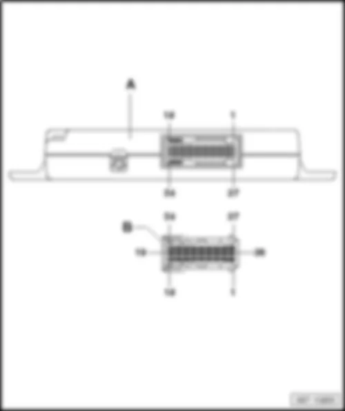
VW CADDY 2013 Data bus diagnostic interface J533

Data bus diagnostic interface -J533-
Fitting location:
left under dash panel, above the relay carrier -arrow-
 
VW CADDY 2013 Data bus diagnostic interface J533 https://portal-diagnostov.com/license.html
https://portal-diagnostov.com/license.html Automotive Electricians Portal FZCO Automotive Electricians Portal FZCO
すべての配線図にアクセスする車Download PDF file
Connector assignment:
VW CADDY 2013 Data bus diagnostic interface J533 https://portal-diagnostov.com/license.html
https://portal-diagnostov.com/license.html Automotive Electricians Portal FZCO Automotive Electricians Portal FZCO
すべての配線図にアクセスする車Download PDF file
A -  Data bus diagnostic interface -J533-
Connector:
B -  20-pin connector, red -T20-

Back to overview


VW CADDY 2013 Voltage stabiliser J532

Voltage stabiliser -J532-
Fitting location:
left under dash panel, behind the relay carrier
   
VW CADDY 2013 Voltage stabiliser J532 https://portal-diagnostov.com/license.html
https://portal-diagnostov.com/license.html Automotive Electricians Portal FZCO Automotive Electricians Portal FZCO
すべての配線図にアクセスする車Download PDF file
1 -  Voltage stabiliser -J532-
A -  12-pin connector, black -T12c-

Back to overview


VW CADDY 2013

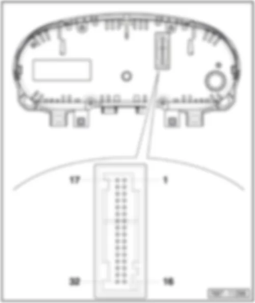
Dash panel insert -K- with control unit in dash panel insert -J285-
Connector assignment for 32-pin connector, blue -T32-
VW CADDY 2013 https://portal-diagnostov.com/license.html
https://portal-diagnostov.com/license.html Automotive Electricians Portal FZCO Automotive Electricians Portal FZCO
すべての配線図にアクセスする車Download PDF file
1 -  Fuel gauge sensor -G- (full)
2 -  Fuel gauge sensor -G- (empty)
3 -  Fuel gauge sensor 2 -G169- (full)
4 -  Fuel gauge sensor 2 -G169- (empty)
5 -  -
6 -  -
7 -  Immobiliser reader coil -D2-
8 -  Immobiliser reader coil -D2-
9 -  Output for speed signal
10 -  -
11 -  Oil level and oil temperature sender -G266-
12 -  -
13 -  -
14 -  -
15 -  -
16 -  Terminal 31
17 -  Windscreen washer fluid level sender -G33- (washer fluid level warning lamp -K37- )
18 -  Coolant shortage indicator sender -G32- (coolant temperature and coolant shortage warning lamp -K28- )
19 -  Ambient temperature sensor -G17-
20 -  Earth for sensor
21 -  -
22 -  -
23 -  -
24 -  -
25 -  Handbrake warning switch -F9- (handbrake warning lamp -K139- )
26 -  Brake fluid level warning contact -F34- (brake fluid level warning lamp -K33- )
27 -  Oil pressure switch -F1- (oil pressure warning lamp -K3- )
28 -  Data bus diagnostic interface -J533- CAN bus, high
29 -  Data bus diagnostic interface -J533- CAN bus, low
30 -  -
31 -  Terminal 15a
32 -  Terminal 30a

Back to overview


VW CADDY 2013

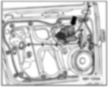
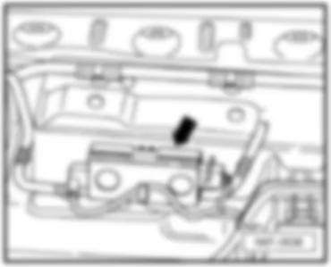
Wiper motor control unit -J400- , on windscreen wiper motor -V-
Fitting location:
on left in plenum chamber.
   
VW CADDY 2013 https://portal-diagnostov.com/license.html
https://portal-diagnostov.com/license.html Automotive Electricians Portal FZCO Automotive Electricians Portal FZCO
すべての配線図にアクセスする車Download PDF file
1 -  Wiper motor control unit -J400-
A -  4-pin connector, black -T4p-

Back to overview


VW CADDY 2013 Battery monitoring control unit J367

Battery monitoring control unit -J367-
Fitting location:
At battery negative terminal.
   
VW CADDY 2013 Battery monitoring control unit J367 https://portal-diagnostov.com/license.html
https://portal-diagnostov.com/license.html Automotive Electricians Portal FZCO Automotive Electricians Portal FZCO
すべての配線図にアクセスする車Download PDF file
1 -  Battery monitoring control unit -J367-
A -  2-pin connector -T2-

Back to overview


VW CADDY 2013 Control unit for cornering light and headlight range control J745

Control unit for cornering light and headlight range control -J745-
Fitting location:
Under dash panel on left.
  Note
t  The figure shows a left-hand drive vehicle.
t  On right-hand drive vehicles, theControl unit for cornering light and headlight range control -J745- on the right under the dash panel
   
VW CADDY 2013 Control unit for cornering light and headlight range control J745 https://portal-diagnostov.com/license.html
https://portal-diagnostov.com/license.html Automotive Electricians Portal FZCO Automotive Electricians Portal FZCO
すべての配線図にアクセスする車Download PDF file
1 -  Control unit for cornering light and headlight range control -J745-
A -  26-pin connector -T26b-

Back to overview


VW CADDY 2013 Remote control receiver for auxiliary coolant heater R149

Remote control receiver for auxiliary coolant heater -R149-
Fitting location:
Under dash panel on left.
  Note
t  The figure shows a left-hand drive vehicle.
t  On right-hand drive vehicles, theRemote control receiver for auxiliary coolant heater -R149- on the right under the dash panel
   
VW CADDY 2013 Remote control receiver for auxiliary coolant heater R149 https://portal-diagnostov.com/license.html
https://portal-diagnostov.com/license.html Automotive Electricians Portal FZCO Automotive Electricians Portal FZCO
すべての配線図にアクセスする車Download PDF file
1 -  Remote control receiver for auxiliary coolant heater -R149-
A -  6-pin connector, blue -T6v-
B -  Aerial connection point

Back to overview


VW CADDY 2013 Overview of fuse carriers in vehicle interior

Overview of fuse carriers in vehicle interior
   
VW CADDY 2013 Overview of fuse carriers in vehicle interior https://portal-diagnostov.com/license.html
https://portal-diagnostov.com/license.html Automotive Electricians Portal FZCO Automotive Electricians Portal FZCO
すべての配線図にアクセスする車Download PDF file
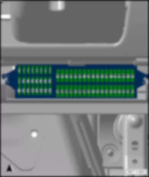
1 -  Fuses (SC) on fuse holder C
q   Fuse assignment

   
Fuses on fuse holder C -SC- , on left under dash panel
Fuse colours
VW CADDY 2013 Overview of fuse carriers in vehicle interior https://portal-diagnostov.com/license.html
https://portal-diagnostov.com/license.html Automotive Electricians Portal FZCO Automotive Electricians Portal FZCO
すべての配線図にアクセスする車Download PDF file
40 A -  orange
30 A -  light green
25 A -  clear (transparent)
20 A -  yellow
15 A -  light blue
10 A -  red
7,5 A -  brown
5 A -  light brown (beige)
3 A -  purple


VW CADDY 2013 Fuse assignment on fuse holder C SC

Fuse assignment on fuse holder C -SC-
No.   Current Flow Diagram designation Nominal value   Function/component Terminal
1 - Fuse 1 on fuse holder C -SC1- - - - -
2 - Fuse 2 on fuse holder C -SC2- - - - -
3 - Fuse 3 on fuse holder C -SC3- - - - -
4 - Fuse 4 on fuse holder C -SC4- - - - -
5 - Fuse 5 on fuse holder C -SC5- - - - -
6 - Fuse 6 on fuse holder C -SC6- - - - -
7 - Fuse 7 on fuse holder C -SC7- - - - -
8 - Fuse 8 on fuse holder C -SC8- - - - -
9 - Fuse 9 on fuse holder C -SC9- 10A - -Sonderfahrzeuge-
t  4-pin connector -T4aa- , Pin 1 3)
t  10-pin connector -T10l- , Pin 4 (Interface for special functions)
15a
10 - Fuse 10 on fuse holder C -SC10- 5A - Fuel pump relay -J17-
Main relay -J271-
Gas mode control unit -J659-
Terminal 50 voltage supply relay -J682-
Starter relay 1 -J906-
Voltage stabiliser -J532-
Data bus diagnostic interface -J533-
Engine control unit -J623-
15a
11 - Fuse 11 on fuse holder C -SC11- 5A - Parking aid control unit -J446-
Park assist steering control unit -J791-
15a
12 - Fuse 12 on fuse holder C -SC12- 5A - -Sonderfahrzeuge-
t  Taximeter -G41-
t  Mirror taximeter -G511-
15a
    10A3) - -Sonderfahrzeuge-3)
t  2-pin connector -T2ab- , Pin 1
t  2-pin connector -T2ac- , Pin 1
t  28-pin connector -T28b- , Pin 13
15a
    20A4) - -Sonderfahrzeuge-4)
t  8-pin connector -T8k- , Pin 8
t  28-pin connector -T28a- , Pin 20
t  28-pin connector -T28b- , Pin 20
15a
13 - Fuse 13 on fuse holder C -SC13- 7.5 A - Brake light switch -F-3)
Headlight range control adjuster -E102-
TCS and ESP button -E256-
Tyre pressure monitor display button -E492-
Start/Stop operation button -E693-
ABS control unit -J104-
Trailer detector control unit -J345-
All-wheel drive control unit -J492-
Power steering control unit -J500-
Selector lever sensors control unit -J587-
Mechatronic unit for dual clutch gearbox -J743-
Left headlight range control motor -V48-
Right headlight range control motor -V49-
Control unit for cornering light and headlight range control -J745-
15a
14 - Fuse 14 on fuse holder C -SC14- 10A - Reversing light switch -F4-
Air mass meter -G70-
Auxiliary heater operation relay -J485-
Control unit in dash panel insert -J285-
Heater element for crankcase breather -N79-
Activated charcoal filter solenoid valve 1 -N80-
Diagnostic connection -U31-16-pin connector -T16- , Pin 1
15a
15 - Fuse 15 on fuse holder C -SC15- 5A - Airbag control unit -J234-
Front passenger side airbag deactivated warning lamp -K145-
15a
16 - Fuse 16 on fuse holder C -SC16- 5A - Light switch -E1-
Heater/heat output switch -E16-
High-pressure sender -G65-
Air quality sensor -G238-
Oil level and oil temperature sender -G266-
Automatic anti-dazzle interior mirror -Y7-
15a
17 - Fuse 17 on fuse holder C -SC17- - - - -
18 - Fuse 18 on fuse holder C -SC18- 10A - -Sonderfahrzeuge-
t  Taxi alarm remote control control unit -J601-
30
    10A - -Sonderfahrzeuge-
t  10-pin connector -T10l- , Pin 6 (Interface for special functions)
BLL
19 - Fuse 19 on fuse holder C -SC19- 10A - -Sonderfahrzeuge-
t  Taximeter -G41-
t  Mirror taximeter -G511-
t  Taxi alarm remote control control unit -J601-
t  Two-way radio -R8-
t  Printer -R98-
30
    10A - -Sonderfahrzeuge-
t  10-pin connector -T10l- , Pin 7 (Interface for special functions)
BLR
20 - Fuse 20 on fuse holder C -SC20- 20A - Cigarette lighter -U1-7) 30
21 - Fuse 21 on fuse holder C -SC21- 10A - Light switch -E1-
Heater/heat output switch -E16-
Rain and light sensor -G397-
Heated rear window relay -J9-
Climatronic control unit -J255-
Air conditioning system control unit -J301-
Horn relay -J413-
Remote control receiver for auxiliary coolant heater -R149-
Selector lever sensors control unit -J587-
Diagnostic connection -U31-16-pin connector -T16- , Pin 16
Switch for interior lighting -E599- (Camper)
Rear interior light -W43- (Camper)
30
22 - Fuse 22 on fuse holder C -SC22- 10A - Onboard supply control unit -J519- (T52b/42) 2) 30
23 - Fuse 23 on fuse holder C -SC23- 5A - -Sonderfahrzeuge-
t  Interior light switch (taxi) -E115-
t  Taxi sign switch -E138-
t  10-pin connector -T10l- , Pin 1 (Interface for special functions)
30
    10A - -Sonderfahrzeuge-
t  3-pin connector -T3ak- , Pin 1 3)
t  Flashing lights relay -J630-4)
30
24 - Fuse 24 on fuse holder C -SC24- 5A - Interior monitoring sensor -G273-
Vehicle inclination sender -G384-
Anti-theft alarm sensor -G578-
Alarm horn -H12-
Onboard supply control unit -J519- (T52c/1)
30
25 - Fuse 25 on fuse holder C -SC25- 10A - Output module for left headlight -J667- 15a
26 - Fuse 26 on fuse holder C -SC26- 10A - Output module for right headlight -J668- 15a
27 - Fuse 27 on fuse holder C -SC27- - - - 15a
28 - Fuse 28 on fuse holder C -SC28- 20A - 12-V socket 3 -U19- , in storage compart. 75
29 - Fuse 29 on fuse holder C -SC29- 15A - Rear window wiper motor -V12- 75
30 - Fuse 30 on fuse holder C -SC30- - - - 75
31 - Fuse 31 on fuse holder C -SC31- 5A - Heater/heat output switch -E16-
Left washer jet heater element -Z20-
Right washer jet heater element -Z21-
75
32 - Fuse 32 on fuse holder C -SC32- - - - -
33 - Fuse 33 on fuse holder C -SC33- 40A - Air conditioning system control unit -J301-
Heater/heat output switch -E16-
75
34 - Fuse 34 on fuse holder C -SC34- - - - -
35 - Fuse 35 on fuse holder C -SC35- 10A - -Sonderfahrzeuge-3)
t  Fluorescent light in rear of high roof -W41-
t  Fluorescent light in centre of high roof -W42-
30
36 - Fuse 36 on fuse holder C -SC36- - - - -
37 - Fuse 37 on fuse holder C -SC37- - - - -
38 - Fuse 38 on fuse holder C -SC38- - - - -
39 - Fuse 39 on fuse holder C -SC39- 20A - -Sonderfahrzeuge-
t  10-pin connector -T10ai- , Pin 1 3)
30
    30A - -Sonderfahrzeuge-
t  4-pin connector -T4ad- , Pin 1 4)
30
40 - Fuse 40 on fuse holder C -SC40- 20A - Trailer detector control unit -J345- 30
41 - Fuse 41 on fuse holder C -SC41- 20A - Trailer detector control unit -J345- 30
42 - Fuse 42 on fuse holder C -SC42- 20A - Trailer detector control unit -J345- 30
43 - Fuse 43 on fuse holder C -SC43- 15A - Fuel pump relay -J17-
Electric fuel pump 2 relay -J49-
t  Supplementary fuel pump -V393-
30
44 - Fuse 44 on fuse holder C -SC44- 40A - Fresh air blower control unit -J126-
t  Fresh air blower -V2-
30
45 - Fuse 45 on fuse holder C -SC45- 20A - Headlight washer system relay -J39-
t  Headlight washer system pump -V11-
30
46 - Fuse 46 on fuse holder C -SC46- 10A - Onboard supply control unit -J519- (T52b/42) 1)
t  Front interior light -W1-
t  Luggage compartment light -W3-
t  Glove compartment light -W6-
t  Rear interior light -W43-
30
    30A - Driver door control unit -J386-2) 30
47 - Fuse 47 on fuse holder C -SC47- 30A - Cigarette lighter -U1-6)
X-contact relief relay -J59-7)8)
t  Fuse holder C -SC- (-SC28- up to -SC33- ) 7)8)
30
48 - Fuse 48 on fuse holder C -SC48- 30A - Heated front seats control unit -J774- 30
49 - Fuse 49 on fuse holder C -SC49- 30A - Driver door control unit -J386-1)
Front passenger door control unit -J387-
30
50 - Fuse 50 on fuse holder C -SC50- 20A - Onboard supply control unit -J519- (T52b/1)
t  Rear window wiper motor -V12-
t  Windscreen and rear window washer pump -V59-
t  Washer pump -V5-
30
51 - Fuse 51 on fuse holder C -SC51- 15A - Trailer voltage supply relay -J941-
t  Trailer socket -U10- (T13/10)
30
    30A - -Sonderfahrzeuge-
t  10-pin connector -T10ai- , Pin 4
t  10-pin connector -T10ai- , Pin 5
30
52 - Fuse 52 on fuse holder C -SC52- 25A - Heated rear window relay -J9-
t  heated rear window -Z1-
t  Heated rear window in left wing door -Z26-
t  Heated rear window in right wing door -Z27-
Fresh air blower relay -J13-
t  Fresh air blower series resistor with overheating fuse -N24-
t  Fresh air blower -V2-
30
53 - Fuse 53 on fuse holder C -SC53- 15A6)
20A7)
- 12 V socket -U5- , in the rear centre console
12 V socket 2 -U18- , In rear left side panel
30
54 - Fuse 54 on fuse holder C -SC54- 15A - -Sonderfahrzeuge-4)
t  Switch-over relay 1 for roof ventilator -J180-
30
55 - Fuse 55 on fuse holder C -SC55- 15A - -Sonderfahrzeuge-4)
t  8-pin connector -T8m- , Pin 4
t  8-pin connector -T8n- , Pin 4
30
56 - Fuse 56 on fuse holder C -SC56- - - - -
57 - Fuse 57 on fuse holder C -SC57- 5A - Control unit in dash panel insert -J285-5)
Steering column electronics control unit -J527-5)
30
58 - Fuse 58 on fuse holder C -SC58- 5A - Mobile telephone operating electronics control unit -J412-5) 30
59 - Fuse 59 on fuse holder C -SC59- 5A - -Sonderfahrzeuge-
t  Radio switch -E72-
t  Ignition bypass button -E489-
t  Button for daytime running light switch-off -E652-
t  Accident data memory -J754-
30
60 - Fuse 60 on fuse holder C -SC60- 30A - -Sonderfahrzeuge-
t  3-pin connector -T3al- , Pin 1
30

t  1) before April 2011
t  2) after May 2011
t  3) before October 2011
t  4) after November 2011
t  5) for vehicles with start-stop system only
t  6) before October 2012
t  7) after November 2012
t  8) for vehicles with Climatronic only


VW CADDY 2013 Overview of fuse holders in engine compartment

Overview of fuse holders in engine compartment
VW CADDY 2013 Overview of fuse holders in engine compartment https://portal-diagnostov.com/license.html
https://portal-diagnostov.com/license.html Automotive Electricians Portal FZCO Automotive Electricians Portal FZCO
すべての配線図にアクセスする車Download PDF file
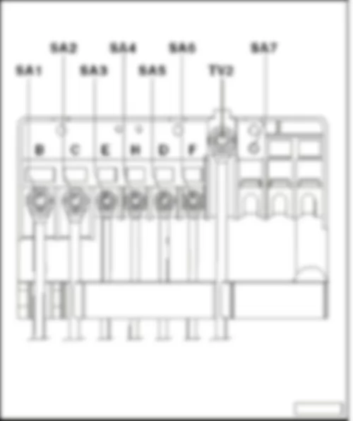
1 -  Fuses on fuse holder A -SA-
q   Fuse assignment
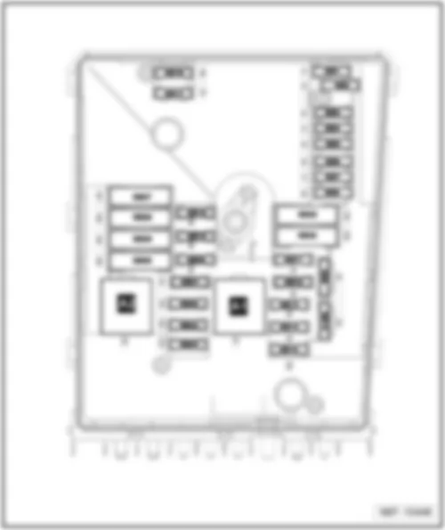
2 -  Fuses on fuse holder B -SB-
q   Fuse assignment

Fuses on fuse holder A -SA- on the front of the E-box, in​ engine​ compart., left, beside the battery -A-
Specified torque settings
⇒ Electrical system, Repair Group 97, Removing and installing fuse holders
Fuse colours
   
VW CADDY 2013 Overview of fuse holders in engine compartment https://portal-diagnostov.com/license.html
https://portal-diagnostov.com/license.html Automotive Electricians Portal FZCO Automotive Electricians Portal FZCO
すべての配線図にアクセスする車Download PDF file
200 A -  purple
150 A -  grey
125 A -  pink
100 A -  blue
80 A -  white
70 A -  brown
60 A -  yellow
50 A -  red
40 A -  green
30 A -  orange


VW CADDY 2013 Fuse assignment on fuse holder A SA

Fuse assignment on fuse holder A -SA-
No.   Current Flow Diagram designation Nominal value   Function/component Terminal
1 - Fuse 1 on fuse holder A -SA1- 150 A - Alternator -C- 30
    200 A - Alternator -C-1) 30
2 - Fuse 2 on fuse holder A -SA2- 80 A - Power steering control unit -J500-
Electromechanical power steering motor -V187-
30
3 - Fuse 3 on fuse holder A -SA3- 50 A - Radiator fan control unit -J293- 30
4 - Fuse 4 on fuse holder A -SA4- 80 A - X-contact relief relay -J59-
t  Fuse holder C -SC- (-SC28- up to -SC33- )
30
5 - Fuse 5 on fuse holder A -SA5- 80 A - Fuse holder C -SC- (-SC20- up to -SC24- and -SC43- up to -SC53- ) 30
6 - Fuse 6 on fuse holder A -SA6- 40 A - Low heat output relay -J359- 30
7 - Fuse 7 on fuse holder A -SA7- 80 A - High heat output relay -J360- 30

  Note
1) Models with 140 A generator only


VW CADDY 2013

Fuses on fuse holder B -SB- on the E-box, in​ engine​ compart., left, beside the battery -A-
Fuse colours
VW CADDY 2013 https://portal-diagnostov.com/license.html
https://portal-diagnostov.com/license.html Automotive Electricians Portal FZCO Automotive Electricians Portal FZCO
すべての配線図にアクセスする車Download PDF file
40 A -  orange
30 A -  light green
25 A -  natural (white)
20 A -  yellow
15 A -  light blue
10 A -  red
7,5 A -  brown
5 A -  light brown (beige)
3 A -  purple


VW CADDY 2013 Fuse locations on fuseholder B SB

Fuse locations on fuseholder B -SB-
No.   Current Flow Diagram designation Nominal value   Function/component Terminal
1 - Fuse 1 on fuse holder B -SB1- - - - -
2 - Fuse 2 on fuse holder B -SB2- 30 A - Mechatronic unit for dual clutch gearbox -J743- 30
3 - Fuse 3 on fuse holder B -SB3- 5 A - Battery monitoring control unit -J367-
Onboard supply control unit -J519- (T52a/24)
30
4 - Fuse 4 on fuse holder B -SB4- 20 A - ABS control unit -J104-
ABS hydraulic unit -N55-
30
5 - Fuse 5 on fuse holder B -SB5- 15 A - Mechatronic unit for dual clutch gearbox -J743- 30
6 - Fuse 6 on fuse holder B -SB6- 5 A - Control unit in dash panel insert -J285-
Steering column electronics control unit -J527-
30
7 - Fuse 7 on fuse holder B -SB7- 40 A - Terminal 15 voltage supply relay -J329-
t  Fuse holder C -SC- (-SC9- up to -SC16- and -SC25- up to -SC27- )
30
8 - Fuse 8 on fuse holder B -SB8- 15 A
- Control unit with display for radio and navigation -J503-
Radio -R-
Voltage stabiliser -J532-3)
t  Control module with display unit for radio and navigation system -J503-
t  Radio -R-
t  Fuse 57 on fuse holder C -SC57-
t  Fuse 58 on fuse holder C -SC58-
30
9 - Fuse 9 on fuse holder B -SB9- 5 A - Mobile telephone operating electronics control unit -J412-4) 30
10 - Fuse 10 on fuse holder B -SB10- 5 A - Main relay -J271-
Engine control unit -J623-
Engine component current supply relay -J757-
30
11 - Fuse 11 on fuse holder B -SB11- 30 A - Auxiliary heater control unit -J364- 30
12 - Fuse 12 on fuse holder B -SB12- 5 A - Data bus diagnostic interface -J533- 30
13 - Fuse 13 on fuse holder B -SB13- 15 A - Engine control unit -J623- (petrol engine) 87a
    30 A - Engine control unit -J623- (diesel engine) 87a
14 - Fuse 14 on fuse holder B -SB14- 15 A - Fuel pressure regulating valve -N276- (diesel engine)
Fuel metering valve -N290- (diesel engine)
87a
    20 A - Ignition transformer -N152-
Ignition coil 1 with output stage -N70-
Ignition coil 2 with output stage -N127-
Ignition coil 3 with output stage -N291-
Ignition coil 4 with output stage -N292-
87a
15 - Fuse 15 on fuse holder B -SB15- 5 A - Low heat output relay -J359- (diesel engine)
High heat output relay -J360- (diesel engine)
Fuel pump relay -N17-
Electric fuel pump 2 relay -J49-
Automatic glow period control unit -J179-
87a
    10 A - Lambda probe heater -Z19-
Lambda probe 1 heater after catalytic converter -Z29-
Low heat output relay -J359-
High heat output relay -J360-
Fuel pump switch-off relay -J333-2)
Gas injection valve 1 -N366-1)
Gas injection valve 2 -N367-1)
Gas injection valve 3 -N368-1)
Gas injection valve 4 -N369-1)
87a
    15 A - High-pressure valve for gas mode -N372-2)
Valve for gas tank -N495-2)
Sensor for gas level gauge -G707-2)
Gas injection valve 1 -N366-2)
Gas injection valve 2 -N367-2)
Gas injection valve 3 -N368-2)
Gas injection valve 4 -N369-2)
87a
16 - Fuse 16 on fuse holder B -SB16- 30 A - Onboard supply control unit -J519- (T52c/42)
t  Light bulb for right foglamp -L23-
t  Right cornering light bulb -L149-
t  Rear left fog light bulb -L46- , or rear right fog light bulb -L47-
t  Right daytime running light bulb -L175-
t  Left side light bulb -M1-
t  Right tail light bulb -M2-
t  Rear left turn signal bulb -M6-
t  Front right turn signal bulb -M7-
t  Left brake light bulb -M9-
t  Right reversing light bulb -M17-
t  Left turn signal repeater bulb -M18-
t  High-mounted brake light bulb -M25-
t  Right headlight dipped beam bulb -M31-
t  Right headlight main beam bulb -M32-
30
17 - Fuse 17 on fuse holder B -SB17- 15 A - Horn relay -J413- 30
18 - Fuse 18 on fuse holder B -SB18- 30 A - Special vehicle control unit -J608- 30
19 - Fuse 19 on fuse holder B -SB19- 30 A - Wiper motor control unit -J400- 30
20 - Fuse 20 on fuse holder B -SB20- 10 A - Fuel tank shut-off valve 1 -N361-1)
Fuel tank shut-off valve 2 -N362-1)
Fuel tank shut-off valve 3 -N363-1)
Fuel tank shut-off valve 4 -N429-1)
Fuel tank shut-off valve 5 -N430-1)
Coolant circulation pump -V50-
87a
21 - Fuse 21 on fuse holder B -SB21- 10 A - Lambda probe heater -Z19- (diesel engine) 87a
    15 A - Fuel pump control unit -J538-
Lambda probe heater -Z19-
Lambda probe 1 heater after catalytic converter -Z29-
87a
22 - Fuse 22 on fuse holder B -SB22- 5 A - Clutch position sender -G476-
Brake light switch -F-5)
87a
23 - Fuse 23 on fuse holder B -SB23- 5 A - Additional coolant pump relay -J496- 87a
    10 A - Air mass meter -G70- (Diesel engine)
Charge pressure control solenoid valve -N75- (Diesel engine)
Exhaust gas recirculation cooler changeover valve -N345- (Diesel engine)
Control unit for gas mode -J659-
Relay for gas shut-off valves -J908-1)
High-pressure valve for gas mode -N372-1)
87a
    15 A - Fuel pressure regulating valve -N276- 87a
24 - Fuse 24 on fuse holder B -SB24- 10 A - Radiator fan control unit -J293-
Secondary air pump relay -J299-
Additional coolant pump relay -J496-
Activated charcoal filter solenoid valve 1 -N80-
Coolant regulating valve -N515-
Variable intake manifold changeover valve -N156-
Coolant circulation pump 2 -V178-
Injector, cylinder 1 -N30-1)
Injector, cylinder 2 -N31-1)
Injector, cylinder 3 -N32-1)
Injector, cylinder 4 -N33-1)
87a
25 - Fuse 25 on fuse holder B -SB25- 40 A - ABS hydraulic pump -V64-
ABS control unit -J104-
30
26 - Fuse 26 on fuse holder B -SB26- 30 A - Onboard supply control unit -J519- (T52a/1)
t  Left cornering light bulb -L148-
t  Left fog light bulb -L22-
t  Rear left fog light bulb -L46- , or rear right fog light bulb -L47-
t  Left daytime running light bulb -L174-
t  Right side light bulb -M3-
t  Left tail light bulb -M4-
t  Front left turn signal bulb -M5-
t  Rear right turn signal bulb -M8-
t  Right brake light bulb -M10-
t  Left reversing light bulb -M16-
t  Right turn signal repeater bulb -M19-
t  Left headlight dipped beam bulb -M29-
t  Left headlight main beam bulb -M30-
30
27 - Fuse 27 on fuse holder B -SB27- 40 A - Secondary air pump motor -V101- 30
    50 A - Automatic glow period control unit -J179- 30
28 - Fuse 28 on fuse holder B -SB28- - - - -
29 - Fuse 29 on fuse holder B -SB29- 30 A - Fuse 18 on fuse holder C -SC18-
Fuse 19 on fuse holder C -SC19-
30
    50 A - Fuse 35 on fuse holder C -SC35-
Fuse 39 on fuse holder C -SC39-
Fuse 54 on fuse holder C -SC54-
Fuse 55 on fuse holder C -SC55-
Fuse 59 on fuse holder C -SC59-
Fuse 60 on fuse holder C -SC60-
30
30 - Fuse 30 on fuse holder B -SB30- 50 A - Fuse holder C -SC- (-SC40- up to -SC42- ) 30

t  1) for vehicles with engine code BSX only
t  2) for vehicles with engine code CHGA only
t  3) for vehicles with start/stop system only
t  4) for vehicles without start/stop system only
t  5) effective since November 2011