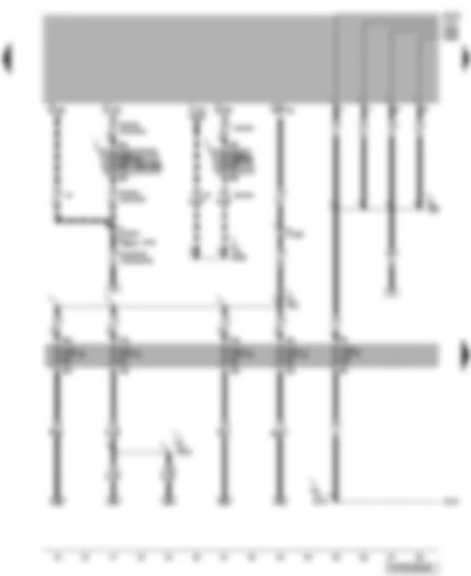
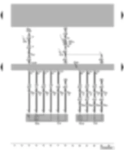
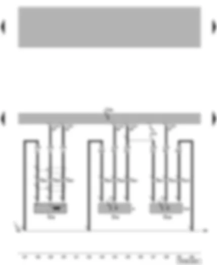
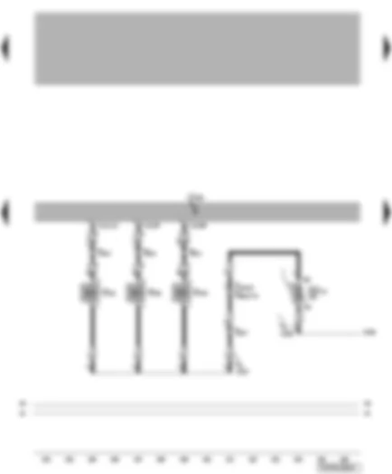
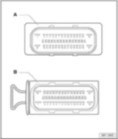
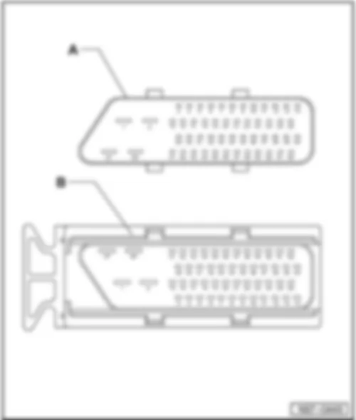
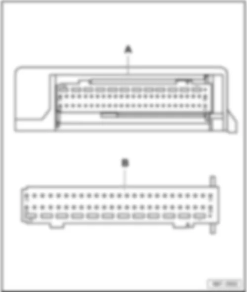
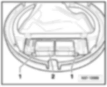
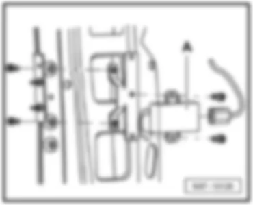
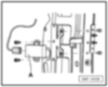
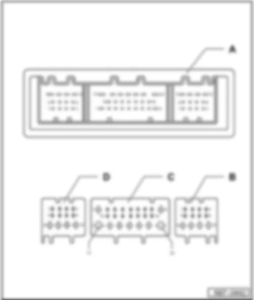
Wiring Diagram VW TRANSPORTER 2005 - Starter - battery - alternator - fuses
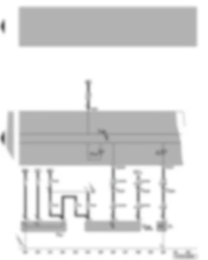
| A | Battery |
| B | Starter |
| C | Alternator |
| C1 | Voltage regulator |
| J207 | Starter inhibitor relay |
| J519 | Onboard supply control unit |
| SA1 | Fuse 1 on fuse holder A |
| SA2 | Fuse 2 on fuse holder A |
| SA3 | Fuse 3 on fuse holder A |
| SA4 | Fuse 4 on fuse holder A |
| SA5 | Fuse 5 on fuse holder A |
| SA6 | Fuse 6 on fuse holder A |
| SA7 | Fuse 7 on fuse holder A |
| SA8 | Fuse 8 on fuse holder A |
| SA9 | Fuse 9 on fuse holder A |
| T6bz | 6-pin connector, light-pink, coupling station on electronics box, in engine compartment |
| T10a | 10-pin connector, brown, coupling station on electronics box, in engine compartment |
| T10m | 10-pin connector, light-pink, coupling station on electronics box, in engine compartment |
| T18a | 18-pin connector, brown |
| D97 | Connection (50), in engine compartment right wiring harness |
| * | Cross-section 4.0 possible |
| ** | models with automatic gearbox / electric interface only ⇒ applicable Current Flow Diagram |
| *** | fuse rating depends on equipment ⇒ Fitting Locations |
| **** | applicable from June 2004 |
| for models with manual gearbox only | |
| for models with automatic gearbox only |
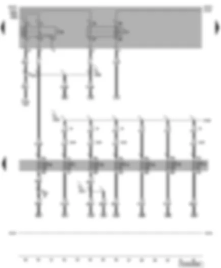
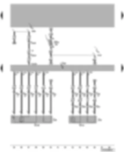
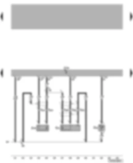
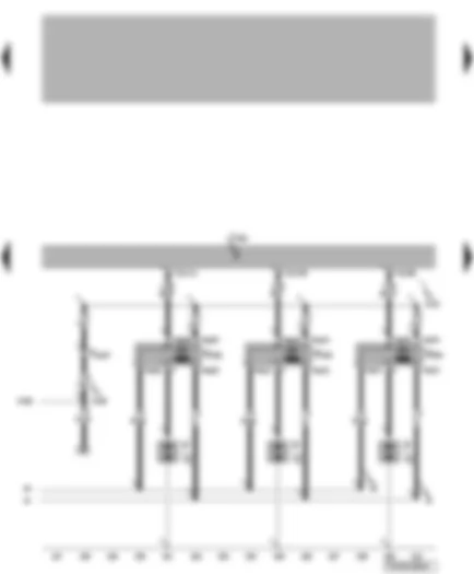
Wiring Diagram VW TRANSPORTER 2005 - Fuses
| D | Ignition/starter switch |
| J519 | Onboard supply control unit |
| SB23 | Fuse 23 on fuse holder B |
| SB34 | Fuse 34 on fuse holder B |
| SD9 | Fuse 9 on fuse holder D |
| SD12 | Fuse 12 on fuse holder D |
| SD14 | Fuse 14 on fuse holder D |
| SD16 | Fuse 16 on fuse holder D |
| SD19 | Fuse 19 on fuse holder D |
| T6e | 6-pin connector, red |
| T6bk | 6-pin connector, grey, coupling station on electronics box, in engine compartment |
| T10 | 10-pin connector, black, coupling station on electronics box, in engine compartment |
| T10a | 10-pin connector, brown, coupling station on electronics box, in engine compartment |
| B276 | Positive connection (50), in main wiring harness |
| D17 | Positive connection 1 (15), in engine harness |
| D50 | Positive connection (30), in engine compartment wiring harness |
| D113 | Connection 11, in engine compartment wiring harness |
| D116 | Connection 14, in engine compartment wiring harness |
| * | applicable up to January 2004 |
| ** | depends on equipment |
| *** | applicable from February 2004 |
| **** | Cross-section 4.0 possible |
| ***** | for models with manual gearbox only |
| for models with manual gearbox and without electric interface only | |
| models with manual gearbox and with electric interface only ⇒ applicable Current Flow Diagram |
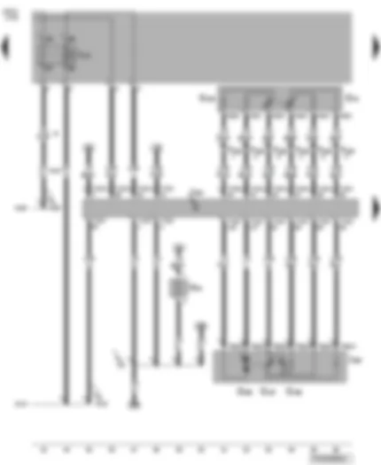
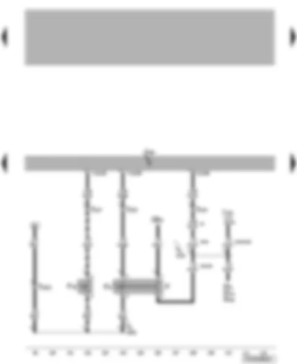
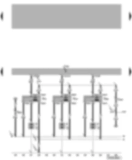
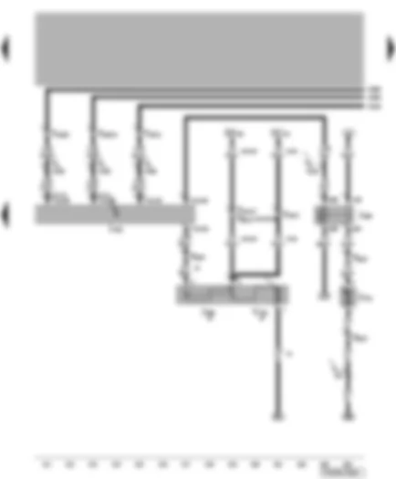
Wiring Diagram VW TRANSPORTER 2005 - Fuses - fuel pump relay
| J17 | Fuel pump relay |
| J49 | Electric fuel pump 2 relay |
| J519 | Onboard supply control unit |
| SD1 | Fuse 1 on fuse holder D |
| SD10 | Fuse 10 on fuse holder D |
| SD25 | Fuse 25 on fuse holder D |
| SD26 | Fuse 26 on fuse holder D |
| SD27 | Fuse 27 on fuse holder D |
| SD30 | Fuse 30 on fuse holder D |
| SD35 | Fuse 35 on fuse holder D |
| T5 | 5-pin connector, black |
| T10c | 10-pin connector, yellow, coupling station on electronics box, in engine compartment |
| T10j | 10-pin connector, dark brown, coupling station on electronics box, in engine compartment |
| D103 | Connection 3, in engine compartment wiring harness |
| D106 | Connection 4, in engine compartment wiring harness |
| D117 | Connection 15, in engine compartment wiring harness |
| * | applicable up to May 2004 |
| ** | applicable from June 2004 |
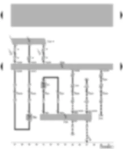
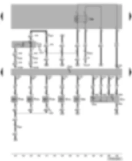
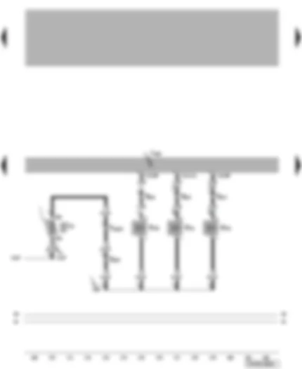
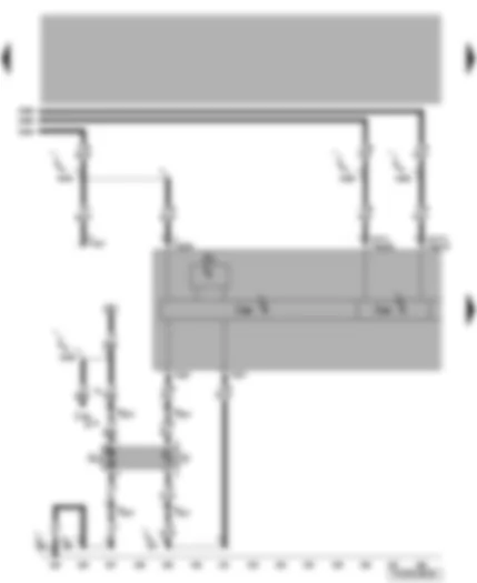
Wiring Diagram VW TRANSPORTER 2005 - Engine control unit - voltage supply relay - accelerator position sender - throttle valve module - heater element for crankcase breather
| G79 | Accelerator position sender |
| G185 | Accelerator position sender 2 |
| G186 | Throttle valve drive (electric power control) |
| G187 | Throttle valve drive angle sender 1 for electric throttle |
| G188 | Throttle valve drive angle sender 2 for electric throttle |
| J317 | Terminal 30 voltage supply relay |
| J338 | Throttle valve module |
| J623 | Engine control unit |
| N79 | Heater element for crankcase breather |
| T6t | 6-pin connector |
| T6az | 6-pin connector |
| T10d | 10-pin connector, blue, coupling station on electronics box, in engine compartment |
| T121 | 121-pin connector |
| 131 | Earth connection 2, in engine compartment wiring harness |
| D103 | Connection 3, in engine compartment wiring harness |
| D113 | Connection 11, in engine compartment wiring harness |
| * | applicable up to May 2004 |
| ** | applicable from June 2004 |
Wiring Diagram VW TRANSPORTER 2005 - Engine control unit - radiator outlet coolant temperature sender - magnetic clutch control unit - radiator fan
| G83 | Radiator outlet coolant temperature sender |
| J153 | Magnetic clutch control unit |
| J293 | Radiator fan control unit |
| J623 | Engine control unit |
| J671 | Radiator fan control unit 2 |
| T2 | 2-pin connector, black |
| T2b | 2-pin connector, black |
| T2c | 2-pin connector, black, near radiator fan |
| T3u | 3-pin connector, black |
| T6u | 6-pin connector, black |
| T10l | 10-pin connector, light-green, coupling station on electronics box, in engine compartment |
| T10n | 10-pin connector, black, coupling station on electronics box, in engine compartment |
| T121 | 121-pin connector |
| V7 | Radiator fan |
| L9 | Connection 1, in air conditioning system wiring harness |
| L10 | Connection 2, in air conditioning system wiring harness |
| * | for models with air conditioning system only ⇒ Current Flow Diagram for radiator fan |
| ** | applicable from January 2005 |
| *** | applicable from January 2006 |
| for models without air conditioning system only | |
| for models with Climatronic/ air conditioning system only ⇒ Current Flow Diagram for radiator fan |
Wiring Diagram VW TRANSPORTER 2005 - Engine control unit - lambda probes
| E45 | Cruise control system switch |
| G39 | Lambda probe |
| G130 | Lambda probe after catalytic converter |
| J623 | Engine control unit |
| SD31 | Fuse 31 on fuse holder D |
| T4k | 4-pin connector, black, on underbody, next to the auxiliary heater |
| T6ax | 6-pin connector, black, in right engine compartment |
| T10 | 10-pin connector, black, coupling station on electronics box, in engine compartment |
| T10d | 10-pin connector, blue, coupling station on electronics box, in engine compartment |
| T10h | 10-pin connector, orange, coupling station on electronics box, in engine compartment |
| T41 | 41-pin connector |
| T121 | 121-pin connector |
| Z19 | Lambda probe heater |
| Z29 | Lambda probe 1 heater after catalytic converter |
| B441 | Connection (CCS), in main wiring harness |
| D119 | Connection 17, in engine compartment wiring harness |
| * | for models with cruise control system only |
Wiring Diagram VW TRANSPORTER 2005 - Engine control unit - lambda probes
| G108 | Lambda probe 2 |
| G131 | Lambda probe 2 after catalytic converter |
| J623 | Engine control unit |
| SD8 | Fuse 8 on fuse holder D |
| T4l | 4-pin connector, brown, on underbody, next to the auxiliary heater |
| T6ay | 6-pin connector, brown, on left in engine compartment |
| T10a | 10-pin connector, brown, coupling station on electronics box, in engine compartment |
| T10h | 10-pin connector, orange, coupling station on electronics box, in engine compartment |
| T10l | 10-pin connector, light-green, coupling station on electronics box, in engine compartment |
| T121 | 121-pin connector |
| Z28 | Lambda probe 2 heater |
| Z30 | Lambda probe 2 heater after catalytic converter |
| B464 | Connection (speed signal), in main wiring harness |
| D118 | Connection 16, in engine compartment wiring harness |
| * | for models with manual gearbox only |
Wiring Diagram VW TRANSPORTER 2005 - Engine control unit - brake light switch - clutch pedal switch - brake light bulb
| F | Brake light switch |
| F36 | Clutch pedal switch |
| F47 | Brake pedal switch |
| J419 | Brake light additional relay |
| J623 | Engine control unit |
| M9 | Left brake light bulb |
| M10 | Right brake light bulb |
| M25 | High level brake light bulb |
| SB9 | Fuse 9 on fuse holder B |
| T10 | 10-pin connector, black, coupling station on electronics box, in engine compartment |
| T10h | 10-pin connector, orange, coupling station on electronics box, in engine compartment |
| T121 | 121-pin connector |
| B131 | Connection (54), in interior wiring harness |
| B278 | Positive connection 2 (15a), in main wiring harness |
| * | applicable up to May 2004 |
| ** | applicable from June 2004 |
| *** | for models without ESP only |
| **** | for models with ESP only |
| for models with manual gearbox only | |
| # | only models with ESP and without serial trailer towing coupling |
| ## | only models with ESP and serial trailer towing coupling |
Wiring Diagram VW TRANSPORTER 2005 - Intake air temperature sender - air mass meter - additional coolant pump relay - valves - continued coolant circulation pump - fuel system diagnostic pump
| G42 | Intake air temperature sender |
| G70 | Air mass meter |
| J496 | Additional coolant pump relay |
| J623 | Engine control unit |
| N80 | Activated charcoal filter system solenoid valve 1 |
| N112 | Secondary air inlet valve |
| N156 | Variable intake manifold change-over valve |
| N205 | Inlet camshaft control valve 1 |
| N318 | Exhaust camshaft control valve 1 |
| T5h | 5-pin connector, brown |
| T10f | 10-pin connector, green, coupling station on electronics box, in engine compartment |
| T10h | 10-pin connector, orange, coupling station on electronics box, in engine compartment |
| T10j | 10-pin connector, dark brown, coupling station on electronics box, in engine compartment |
| T10l | 10-pin connector, light-green, coupling station on electronics box, in engine compartment |
| T121 | 121-pin connector |
| V51 | Continued coolant circulation pump |
| V144 | Fuel system diagnostic pump |
| D114 | Connection 12, in engine compartment wiring harness |
| D120 | Connection 18, in engine compartment wiring harness |
| * | ⇒ auxiliary coolant heater Current Flow Diagram |
| ** | for models with engine code BDM only |
Wiring Diagram VW TRANSPORTER 2005 - Engine control unit - engine speed sender - Hall sender
| G28 | Engine speed sender |
| G40 | Hall sender |
| G163 | Hall sender 2 |
| J623 | Engine control unit |
| T3a | 3-pin connector, black, on front of engine |
| T3b | 3-pin connector, grey, on front of engine |
| T3c | 3-pin connector, black, on front of engine |
| T121 | 121-pin connector |
| 220 | Earth connection (sender earth), in engine wiring harness |
| D141 | Connection (5V), in engine wiring harness |
| * | Camshaft sender - Inlet valves |
| ** | Camshaft sender - Outlet valves |
Wiring Diagram VW TRANSPORTER 2005 - Engine control unit - knock sensors - coolant temperature sender
| G61 | Knock sensor 1 |
| G62 | Coolant temperature sender |
| G66 | Knock sensor 2 |
| J623 | Engine control unit |
| T2a | 2-pin connector, black, on front of engine |
| T3d | 3-pin connector, black, on front of engine |
| T121 | 121-pin connector |
| 139 | Earth connection (sender earth), in Motronic wiring harness |
| 220 | Earth connection (sender earth), in engine wiring harness |
Wiring Diagram VW TRANSPORTER 2005 - Engine control unit - ignition coils 1 up to 3
| J623 | Engine control unit |
| N70 | Ignition coil 1 with output stage |
| N127 | Ignition coil 2 with output stage |
| N291 | Ignition coil 3 with output stage |
| P | Spark plug connector |
| Q | Spark plugs |
| T4aa | 4-pin connector |
| T4ab | 4-pin connector |
| T4ac | 4-pin connector |
| T6q | 6-pin connector, brown, coupling station on electronics box, in engine compartment |
| T10e | 10-pin connector, white, coupling station on electronics box, in engine compartment |
| T121 | 121-pin connector |
| 91 | Earth connection 1, in fully electronic ignition system wiring harness |
| 92 | Earth connection 2, in fully electronic ignition system wiring harness |
| D107 | Connection 5, in engine compartment wiring harness |
| D121 | Connection 19, in engine compartment wiring harness |
Wiring Diagram VW TRANSPORTER 2005 - Engine control unit - injectors for cylinders 1 to 3 - fuse
| J623 | Engine control unit |
| N30 | Injector, cylinder 1 |
| N31 | Injector, cylinder 2 |
| N32 | Injector, cylinder 3 |
| SD22 | Fuse 22 on fuse holder D |
| T8r | 8-pin connector, black, in engine compartment |
| T10e | 10-pin connector, white, coupling station on electronics box, in engine compartment |
| T121 | 121-pin connector |
| D95 | Connection (injectors), in engine compartment wiring harness |
| D107 | Connection 5, in engine compartment wiring harness |
Wiring Diagram VW TRANSPORTER 2005 - Engine control unit - injectors for cylinders 4 to 6 - fuse
| J623 | Engine control unit |
| N33 | Injector, cylinder 4 |
| N83 | Injector, cylinder 5 |
| N84 | Injector, cylinder 6 |
| SD13 | Fuse 13 on fuse holder D |
| T6bz | 6-pin connector, light-pink, coupling station on electronics box, in engine compartment |
| T8r | 8-pin connector, black, in engine compartment |
| T10m | 10-pin connector, light-pink, coupling station on electronics box, in engine compartment |
| T121 | 121-pin connector |
| D108 | Connection 6, in engine compartment wiring harness |
| D137 | Connection 2 (injectors), in engine compartment wiring harness |
| * | applicable from June 2004 |
Wiring Diagram VW TRANSPORTER 2005 - Engine control unit - ignition coils 4 up to 6
| J623 | Engine control unit |
| N292 | Ignition coil 4 with output stage |
| N323 | Ignition coil 5 with output stage |
| N324 | Ignition coil 6 with output stage |
| P | Spark plug connector |
| Q | Spark plugs |
| T4ad | 4-pin connector |
| T4ae | 4-pin connector |
| T4af | 4-pin connector |
| T10e | 10-pin connector, white, coupling station on electronics box, in engine compartment |
| T121 | 121-pin connector |
| 91 | Earth connection 1, in fully electronic ignition system wiring harness |
| 92 | Earth connection 2, in fully electronic ignition system wiring harness |
| D108 | Connection 6, in engine compartment wiring harness |
| D122 | Connection 20, in engine compartment wiring harness |
Wiring Diagram VW TRANSPORTER 2005 - Engine control unit - secondary air pump motor - vacuum pump for brakes
| J299 | Secondary air pump relay |
| J569 | Brake servo relay |
| J623 | Engine control unit |
| SC34 | Fuse 34 on fuse holder C |
| SD29 | Fuse 29 on fuse holder D |
| T6q | 6-pin connector, brown, coupling station on electronics box, in engine compartment |
| T6bz | 6-pin connector, light-pink, coupling station on electronics box, in engine compartment |
| T10a | 10-pin connector, brown, coupling station on electronics box, in engine compartment |
| T10d | 10-pin connector, blue, coupling station on electronics box, in engine compartment |
| T10h | 10-pin connector, orange, coupling station on electronics box, in engine compartment |
| T10m | 10-pin connector, light-pink, coupling station on electronics box, in engine compartment |
| T121 | 121-pin connector |
| V101 | Secondary air pump motor |
| V192 | Vacuum pump for brakes |
| 132 | Earth connection 3, in engine compartment wiring harness |
| D159 | Connection (high bus), in engine compartment wiring harness |
| D160 | Connection (low bus), in engine compartment wiring harness |
| D166 | Connection (K-diagnosis wiring), in engine compartment wiring harness |
| D123 | Connection 21, in engine compartment wiring harness |
| * | for models with automatic gearbox only |
| ** | for models with automatic gearbox only, applicable up to January 2004 |
| *** | for models with automatic gearbox only, applicable from February 2004 |
| **** | applicable from June 2004 |
Wiring Diagram VW TRANSPORTER 2005 - Control unit in dash panel insert - fuel gauge sender - fuel system pressurisation pump
| G | Fuel gauge sender |
| G1 | Fuel gauge |
| G6 | Fuel system pressurisation pump |
| J285 | Control unit in dash panel insert |
| J533 | Data bus diagnostic interface |
| J708 | Residual heat relay |
| T6j | 6-pin connector, red, coupling station under driver seat |
| T16 | 16-pin connector, diagnostic connector |
| T32 | 32-pin connector, blue |
| T32a | 32-pin connector, green |
| 366 | Earth connection 1, in main wiring harness |
| 410 | Earth connection 1 (sender earth), in main wiring harness |
| B383 | Connection 1 (drive train CAN bus, high), in main wiring harness |
| B390 | Connection 1 (drive train CAN bus, low), in main wiring harness |
| B429 | Connection (EFPR), in main wiring harness |
| B444 | Connection 1 (diagnosis), in main wiring harness |
| * | depends on equipment ⇒ utilisation of residual heat/ auxiliary coolant heater Current Flow Diagram |
Wiring Diagram VW TRANSPORTER 2005 - Control unit in dash panel insert - oil pressure switch - oil level and oil temperature sender
| F1 | Oil pressure switch |
| G266 | Oil level and oil temperature sender |
| J285 | Control unit in dash panel insert |
| K3 | Oil pressure warning lamp |
| K38 | Oil level warning lamp |
| SC6 | Fuse 6 on fuse holder C |
| T10a | 10-pin connector, brown, coupling station on electronics box, in engine compartment |
| T10b | 10-pin connector, red, coupling station on electronics box, in engine compartment |
| T32 | 32-pin connector, blue |
| T32a | 32-pin connector, green |
| TV7 | Terminal 31 wiring junction |
| 281 | Earth connection 1, in engine harness |
| * | for models with manual gearbox only |
| ** | for models with automatic gearbox only |
| *** | for models with extended servicing intervals only |
VW TRANSPORTER 2005
VW TRANSPORTER 2005 Overview:
| Overview: |

