AUTOMOTIVE ELECTRICIANS PORTAL

VW TRANSPORTER 2008 – Business, multimediaequipment, seat adjustment . Wiring diagrams, Pin Connector, Location

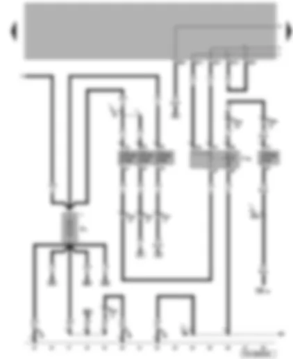
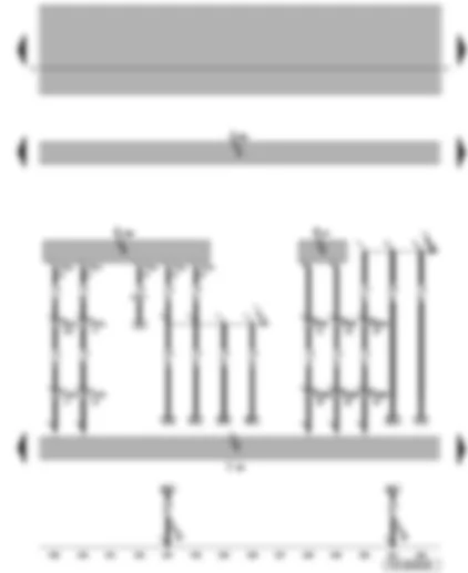
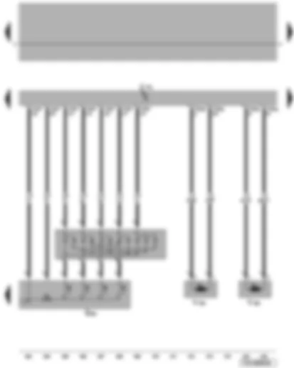
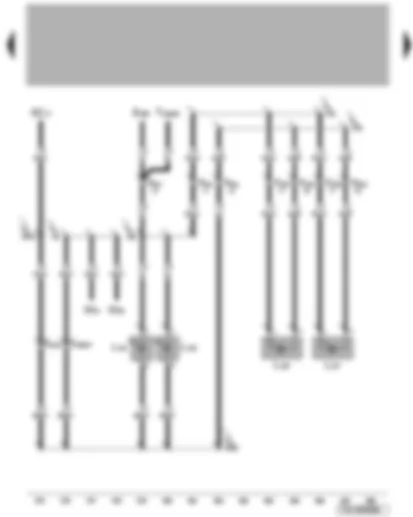
Wiring Diagram VW TRANSPORTER 2008 - Battery - alternator - battery isolation relay - onboard power supply control unit


Wiring Diagram  VW TRANSPORTER 2008 - Battery - alternator - battery isolation relay - onboard power supply control unit https://portal-diagnostov.com/license.html
https://portal-diagnostov.com/license.html Automotive Electricians Portal FZCO Automotive Electricians Portal FZCO
Download PDF file
ABattery
BStarter
CAlternator
C1Voltage regulator
F4Reversing light switch
J...Engine control units
J7Battery isolation relay
J519Onboard supply control unit
S171Battery isolation relay fuse
SA1Fuse 1 on fuse holder A
SA3Fuse 3 on fuse holder A
T6b6-pin connector, red
T6e6-pin connector, red
T6q6-pin connector, brown, coupling station on electronics box, in engine compartment
T10a10-pin connector, brown, coupling station on electronics box, in engine compartment
T10b10-pin connector, red, coupling station on electronics box, in engine compartment
T10bh10-pin connector, purple, coupling station under driver seat
T18a18-pin connector, brown
  B520 Connection (RL), in main wiring harness

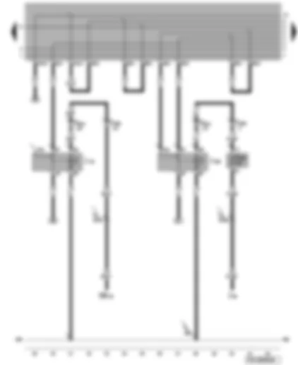
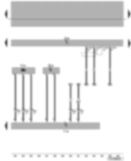
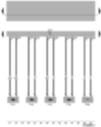
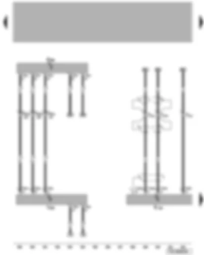
Wiring Diagram VW TRANSPORTER 2008 - Second battery - voltage supply relay 1 - fuses


Wiring Diagram  VW TRANSPORTER 2008 - Second battery - voltage supply relay 1 - fuses https://portal-diagnostov.com/license.html
https://portal-diagnostov.com/license.html Automotive Electricians Portal FZCO Automotive Electricians Portal FZCO
Get access to all wiring diagrams of the carDownload PDF file
A1Second battery
J701Voltage supply relay 1
S291Special vehicle fuse 1
S320Special vehicle fuse 30
S321Special vehicle fuse 31
S322Special vehicle fuse 32
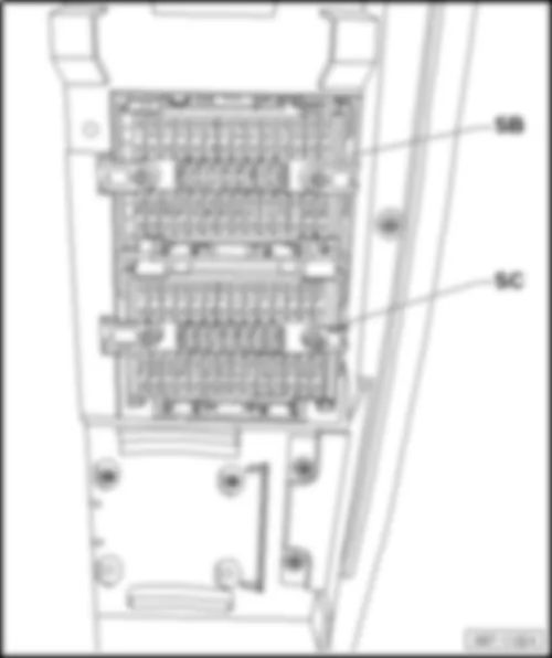
SB19Fuse 19 on fuse holder B
T4xd4-pin connector
T10bh10-pin connector, purple, coupling station under driver seat
T42xa42-pin connector
  455 Earth connection 5, in optional equipment wiring harness
  B518 Connection (86s), in main wiring harness
  P3 Positive connection (30), in 2nd battery wiring harness

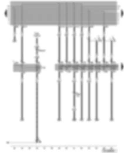
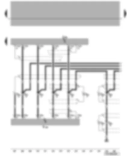
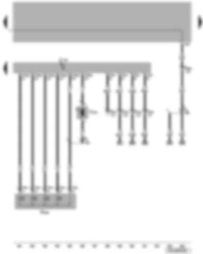
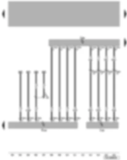
Wiring Diagram VW TRANSPORTER 2008 - Switch illumination relay - terminal 15 voltage supply relay


Wiring Diagram  VW TRANSPORTER 2008 - Switch illumination relay - terminal 15 voltage supply relay https://portal-diagnostov.com/license.html
https://portal-diagnostov.com/license.html Automotive Electricians Portal FZCO Automotive Electricians Portal FZCO
Get access to all wiring diagrams of the carDownload PDF file
J59X-contact relief relay
J141Switch illumination relay
J329Terminal 15 voltage supply relay
S300Special vehicle fuse 10
SB20Fuse 20 on fuse holder B
T10bh10-pin connector, purple, coupling station under driver seat
T42xa42-pin connector
  455 Earth connection 5, in optional equipment wiring harness
  B138 Positive connection (X), in interior wiring harness
  B144 Positive connection (58L), in interior wiring harness

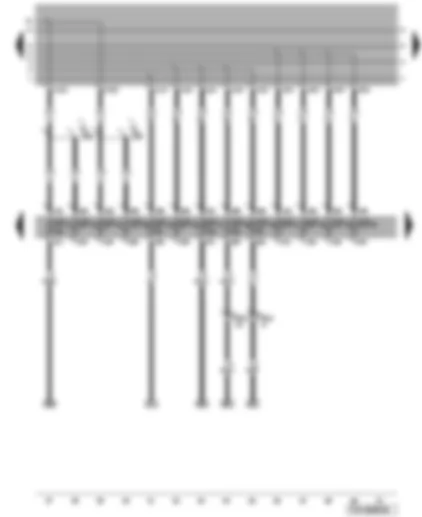
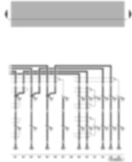
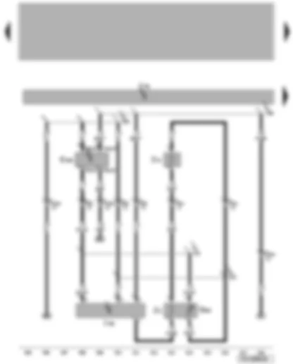
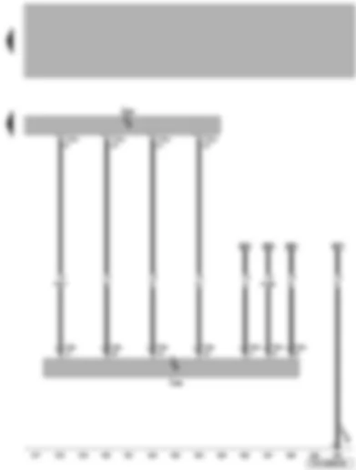
Wiring Diagram VW TRANSPORTER 2008 - Voltage supply relay 2 - fuses


Wiring Diagram  VW TRANSPORTER 2008 - Voltage supply relay 2 - fuses https://portal-diagnostov.com/license.html
https://portal-diagnostov.com/license.html Automotive Electricians Portal FZCO Automotive Electricians Portal FZCO
Get access to all wiring diagrams of the carDownload PDF file
J503Control unit with display for radio and navigation system
J710Voltage supply relay 2
SF14Fuse 14 on fuse holder F
SF15Fuse 15 on fuse holder F
SF16Fuse 16 on fuse holder F
SF17Fuse 17 on fuse holder F
SF18Fuse 18 on fuse holder F
SF19Fuse 19 on fuse holder F
SF20Fuse 20 on fuse holder F
SF37Fuse 37 on fuse holder F
T12m12-pin connector, blue
T42xa42-pin connector
  455 Earth connection 5, in optional equipment wiring harness
  X61 Positive connection (30), in optional equipment wiring harness
  X116 Positive connection 2 (30), in optional equipment wiring harness

Wiring Diagram VW TRANSPORTER 2008 - Fuses


Wiring Diagram  VW TRANSPORTER 2008 - Fuses https://portal-diagnostov.com/license.html
https://portal-diagnostov.com/license.html Automotive Electricians Portal FZCO Automotive Electricians Portal FZCO
Get access to all wiring diagrams of the carDownload PDF file
SF21Fuse 21 on fuse holder F
SF22Fuse 22 on fuse holder F
SF23Fuse 23 on fuse holder F
SF25Fuse 25 on fuse holder F
SF26Fuse 26 on fuse holder F
SF27Fuse 27 on fuse holder F
SF28Fuse 28 on fuse holder F
SF29Fuse 29 on fuse holder F
SF31Fuse 31 on fuse holder F
SF32Fuse 32 on fuse holder F
SF33Fuse 33 on fuse holder F
SF34Fuse 34 on fuse holder F
SF39Fuse 39 on fuse holder F
T42xa42-pin connector
  X144 Positive connection 5 (30), in optional equipment wiring harness
  X147 Positive connection 6 (30), in optional equipment wiring harness

Wiring Diagram VW TRANSPORTER 2008 - Fuses


Wiring Diagram  VW TRANSPORTER 2008 - Fuses https://portal-diagnostov.com/license.html
https://portal-diagnostov.com/license.html Automotive Electricians Portal FZCO Automotive Electricians Portal FZCO
Get access to all wiring diagrams of the carDownload PDF file
SF35Fuse 35 on fuse holder F
SF36Fuse 36 on fuse holder F
SF38Fuse 38 on fuse holder F
SF40Fuse 40 on fuse holder F
SF41Fuse 41 on fuse holder F
SF42Fuse 42 on fuse holder F
SF43Fuse 43 on fuse holder F
SF44Fuse 44 on fuse holder F
SF45Fuse 45 on fuse holder F
SF46Fuse 46 on fuse holder F
SF48Fuse 48 on fuse holder F
SF49Fuse 49 on fuse holder F
SF50Fuse 50 on fuse holder F
SF51Fuse 51 on fuse holder F
T42xa42-pin connector
  X73 Connection 1 (S contact), in optional equipment wiring harness
  X74 Connection 2 (S contact), in optional equipment wiring harness
  X142 Positive connection 3 (30), in optional equipment wiring harness
  X143 Positive connection 4 (30), in optional equipment wiring harness
  X172 Connection 3 (S contact), in optional equipment wiring harness

Wiring Diagram VW TRANSPORTER 2008 - Multimedia control unit - TV tuner


Wiring Diagram  VW TRANSPORTER 2008 - Multimedia control unit - TV tuner https://portal-diagnostov.com/license.html
https://portal-diagnostov.com/license.html Automotive Electricians Portal FZCO Automotive Electricians Portal FZCO
Get access to all wiring diagrams of the carDownload PDF file
J650Multimedia control unit
R78TV tuner
T2xc2-pin connector
T6xe6-pin connector
T12xe12-pin connector
T42xa42-pin connector
T54xa54-pin connector
  416 Earth connection, in rear armrest wiring harness

Wiring Diagram VW TRANSPORTER 2008 - Multimedia control unit - TV aerials - TV tuner - aerial amplifier for TV


Wiring Diagram  VW TRANSPORTER 2008 - Multimedia control unit - TV aerials - TV tuner - aerial amplifier for TV https://portal-diagnostov.com/license.html
https://portal-diagnostov.com/license.html Automotive Electricians Portal FZCO Automotive Electricians Portal FZCO
Get access to all wiring diagrams of the carDownload PDF file
J650Multimedia control unit
R55TV aerial 1
R56TV aerial 2
R57TV aerial 3
R58TV aerial 4
R78TV tuner
R82Aerial amplifier 1 for TV
R83Aerial amplifier 2 for TV
T12xe12-pin connector
T54xa54-pin connector

Wiring Diagram VW TRANSPORTER 2008 - Control unit with display for radio and navigation system - multimedia control unit


Wiring Diagram  VW TRANSPORTER 2008 - Control unit with display for radio and navigation system - multimedia control unit https://portal-diagnostov.com/license.html
https://portal-diagnostov.com/license.html Automotive Electricians Portal FZCO Automotive Electricians Portal FZCO
Get access to all wiring diagrams of the carDownload PDF file
J503Control unit with display for radio and navigation system
J650Multimedia control unit
T12xf12-pin connector
T12xg12-pin connector
T18xa18-pin connector

Wiring Diagram VW TRANSPORTER 2008 - Control unit with display for radio and navigation system - multimedia control unit


Wiring Diagram  VW TRANSPORTER 2008 - Control unit with display for radio and navigation system - multimedia control unit https://portal-diagnostov.com/license.html
https://portal-diagnostov.com/license.html Automotive Electricians Portal FZCO Automotive Electricians Portal FZCO
Get access to all wiring diagrams of the carDownload PDF file
J503Control unit with display for radio and navigation system
J650Multimedia control unit
T2xd2-pin connector
T12p12-pin connector, green
T12xh12-pin connector
T12xj12-pin connector
T12xk12-pin connector
T16xa16-pin connector

Wiring Diagram VW TRANSPORTER 2008 - Multimedia control unit - telephone transmitter and receiver unit - telephone microphone - telephone aerial


Wiring Diagram  VW TRANSPORTER 2008 - Multimedia control unit - telephone transmitter and receiver unit - telephone microphone - telephone aerial https://portal-diagnostov.com/license.html
https://portal-diagnostov.com/license.html Automotive Electricians Portal FZCO Automotive Electricians Portal FZCO
Get access to all wiring diagrams of the carDownload PDF file
J650Multimedia control unit
R36Telephone transmitter and receiver unit
R38Telephone microphone
R65Telephone aerial
T2xe2-pin connector
T20xa20-pin connector
T42xa42-pin connector

Wiring Diagram VW TRANSPORTER 2008 - Multimedia control unit - DVD player - telephone transmitter and receiver unit - telephone handset - telephone handset 2


Wiring Diagram  VW TRANSPORTER 2008 - Multimedia control unit - DVD player - telephone transmitter and receiver unit - telephone handset - telephone handset 2 https://portal-diagnostov.com/license.html
https://portal-diagnostov.com/license.html Automotive Electricians Portal FZCO Automotive Electricians Portal FZCO
Get access to all wiring diagrams of the carDownload PDF file
J650Multimedia control unit
R7DVD player
R36Telephone transmitter and receiver unit
R37Telephone handset
R116Telephone handset 2
T1Single connector
T4xe4-pin connector
T6xd6-pin connector
T6xf6-pin connector

Wiring Diagram VW TRANSPORTER 2008 - Multimedia system operating unit - multimedia control unit - DVD player


Wiring Diagram  VW TRANSPORTER 2008 - Multimedia system operating unit - multimedia control unit - DVD player https://portal-diagnostov.com/license.html
https://portal-diagnostov.com/license.html Automotive Electricians Portal FZCO Automotive Electricians Portal FZCO
Get access to all wiring diagrams of the carDownload PDF file
E380Multimedia system operating unit
J650Multimedia control unit
R7DVD player
T1aSingle connector
T1bSingle connector
T6xf6-pin connector
T12xl12-pin connector
T12xn12-pin connector

Wiring Diagram VW TRANSPORTER 2008 - Multimedia system operating unit - multimedia control unit - additional connections unit for audio and video


Wiring Diagram  VW TRANSPORTER 2008 - Multimedia system operating unit - multimedia control unit - additional connections unit for audio and video https://portal-diagnostov.com/license.html
https://portal-diagnostov.com/license.html Automotive Electricians Portal FZCO Automotive Electricians Portal FZCO
Get access to all wiring diagrams of the carDownload PDF file
E380Multimedia system operating unit
J650Multimedia control unit
R176Additional connections unit for audio and video
T6xj6-pin connector
T6xk6-pin connector
T6xn6-pin connector
T12xl12-pin connector
T12xn12-pin connector

Wiring Diagram VW TRANSPORTER 2008 - Display unit control unit - multimedia control unit


Wiring Diagram  VW TRANSPORTER 2008 - Display unit control unit - multimedia control unit https://portal-diagnostov.com/license.html
https://portal-diagnostov.com/license.html Automotive Electricians Portal FZCO Automotive Electricians Portal FZCO
Get access to all wiring diagrams of the carDownload PDF file
J146Display unit control unit
J650Multimedia control unit
T12xo12-pin connector
T12xp12-pin connector
T12xq12-pin connector

Wiring Diagram VW TRANSPORTER 2008 - Display unit control unit - multimedia control unit


Wiring Diagram  VW TRANSPORTER 2008 - Display unit control unit - multimedia control unit https://portal-diagnostov.com/license.html
https://portal-diagnostov.com/license.html Automotive Electricians Portal FZCO Automotive Electricians Portal FZCO
Get access to all wiring diagrams of the carDownload PDF file
J146Display unit control unit
J650Multimedia control unit
T15xa15-pin connector
T15xb15-pin connector

Wiring Diagram VW TRANSPORTER 2008 - Multimedia system operating unit - display unit control unit - multimedia control unit


Wiring Diagram  VW TRANSPORTER 2008 - Multimedia system operating unit - display unit control unit - multimedia control unit https://portal-diagnostov.com/license.html
https://portal-diagnostov.com/license.html Automotive Electricians Portal FZCO Automotive Electricians Portal FZCO
Get access to all wiring diagrams of the carDownload PDF file
E380Multimedia system operating unit
J146Display unit control unit
J285Control unit in dash panel insert
J650Multimedia control unit
T6xm6-pin connector
T10xb10-pin connector
T10bj10-pin connector, yellow, coupling station under driver seat
T15xa15-pin connector
T15xb15-pin connector
T3232-pin connector, blue
  292 Earth connection 3, in second battery wiring harness
  B464 Connection (speed signal), in main wiring harness

Wiring Diagram VW TRANSPORTER 2008 - Multimedia system operating unit 2 - display unit control unit - multimedia control unit - rear TV and video display unit


Wiring Diagram  VW TRANSPORTER 2008 - Multimedia system operating unit 2 - display unit control unit - multimedia control unit - rear TV and video display unit https://portal-diagnostov.com/license.html
https://portal-diagnostov.com/license.html Automotive Electricians Portal FZCO Automotive Electricians Portal FZCO
Get access to all wiring diagrams of the carDownload PDF file
E499Multimedia system operating unit 2
J146Display unit control unit
J650Multimedia control unit
R97Rear TV and video display unit
T2xh2-pin connector
T6xo6-pin connector
T10xb10-pin connector
T42xa42-pin connector
  280 Earth connection, in communications wiring harness
  453 Earth connection 3, in optional equipment wiring harness

Wiring Diagram VW TRANSPORTER 2008 - Display unit control unit - front infrared sensor - multimedia control unit - open and close display motor


Wiring Diagram  VW TRANSPORTER 2008 - Display unit control unit - front infrared sensor - multimedia control unit - open and close display motor https://portal-diagnostov.com/license.html
https://portal-diagnostov.com/license.html Automotive Electricians Portal FZCO Automotive Electricians Portal FZCO
Get access to all wiring diagrams of the carDownload PDF file
G166Front infrared sensor
J146Display unit control unit
J650Multimedia control unit
T2xf2-pin connector
T2xg2-pin connector
T3xa3-pin connector
T12xm12-pin connector
V301Open and close display motor

Wiring Diagram VW TRANSPORTER 2008 - Multimedia control unit - headphone connection 1


Wiring Diagram  VW TRANSPORTER 2008 - Multimedia control unit - headphone connection 1 https://portal-diagnostov.com/license.html
https://portal-diagnostov.com/license.html Automotive Electricians Portal FZCO Automotive Electricians Portal FZCO
Get access to all wiring diagrams of the carDownload PDF file
J650Multimedia control unit
R185Headphone connection 1
T6xg6-pin connector
T8xc8-pin connector
T8xd8-pin connector
T8xe8-pin connector
T12xt12-pin connector

Wiring Diagram VW TRANSPORTER 2008 - Coupling points


Wiring Diagram  VW TRANSPORTER 2008 - Coupling points https://portal-diagnostov.com/license.html
https://portal-diagnostov.com/license.html Automotive Electricians Portal FZCO Automotive Electricians Portal FZCO
Get access to all wiring diagrams of the carDownload PDF file
T8xd8-pin connector
T8xe8-pin connector
T8xg8-pin connector
T8xh8-pin connector

Wiring Diagram VW TRANSPORTER 2008 - Headphone connection 2 - headphone connection 3


Wiring Diagram  VW TRANSPORTER 2008 - Headphone connection 2 - headphone connection 3 https://portal-diagnostov.com/license.html
https://portal-diagnostov.com/license.html Automotive Electricians Portal FZCO Automotive Electricians Portal FZCO
Get access to all wiring diagrams of the carDownload PDF file
R186Headphone connection 2
R187Headphone connection 3
T6xh6-pin connector
T6xi6-pin connector
T8xf8-pin connector
T8xj8-pin connector

Wiring Diagram VW TRANSPORTER 2008 - Refrigerator box - fax unit


Wiring Diagram  VW TRANSPORTER 2008 - Refrigerator box - fax unit https://portal-diagnostov.com/license.html
https://portal-diagnostov.com/license.html Automotive Electricians Portal FZCO Automotive Electricians Portal FZCO
Get access to all wiring diagrams of the carDownload PDF file
J698Refrigerator box
R55TV aerial 1
R73Fax unit
T1xaSingle connector
T1xbSingle connector
T2xi2-pin connector
T3xb3-pin connector
T3xc3-pin connector
T42xa42-pin connector
V242Rear air recirculation blower

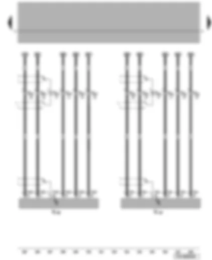
Wiring Diagram VW TRANSPORTER 2008 - Control unit for left seat - row 3


Wiring Diagram  VW TRANSPORTER 2008 - Control unit for left seat - row 3 https://portal-diagnostov.com/license.html
https://portal-diagnostov.com/license.html Automotive Electricians Portal FZCO Automotive Electricians Portal FZCO
Get access to all wiring diagrams of the carDownload PDF file
E561Height adjustment button for front of left seat, row 3
E562Height adjustment button for rear of left seat, row 3
E563Head restraint adjustment button for left seat, row 3
E564Longitudinal adjustment button for left seat, row 3
E565Backrest adjustment button for left seat, row 3
E566Depth adjustment button for left seat, row 3
J782Control unit for left seat, row 3
T20xb20-pin connector

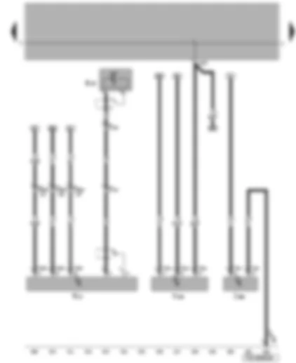
Wiring Diagram VW TRANSPORTER 2008 - Height adjustment button for lumbar support of left seat - row 3 - control unit for left seat - row 3


Wiring Diagram  VW TRANSPORTER 2008 - Height adjustment button for lumbar support of left seat - row 3 - control unit for left seat - row 3 https://portal-diagnostov.com/license.html
https://portal-diagnostov.com/license.html Automotive Electricians Portal FZCO Automotive Electricians Portal FZCO
Get access to all wiring diagrams of the carDownload PDF file
E560Height adjustment button for lumbar support of left seat, row 3
J782Control unit for left seat, row 3
T20xb20-pin connector
T20xc20-pin connector
V368Backrest adjustment motor for left seat, row 3
V371Height adjustment motor 2 for left seat, row 3

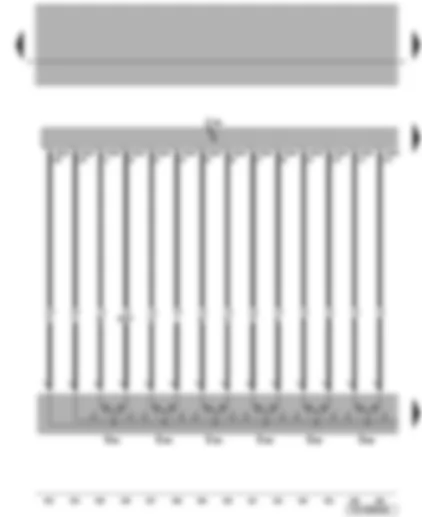
Wiring Diagram VW TRANSPORTER 2008 - Control unit for left seat - row 3


Wiring Diagram  VW TRANSPORTER 2008 - Control unit for left seat - row 3 https://portal-diagnostov.com/license.html
https://portal-diagnostov.com/license.html Automotive Electricians Portal FZCO Automotive Electricians Portal FZCO
Get access to all wiring diagrams of the carDownload PDF file
J782Control unit for left seat, row 3
T6xp6-pin connector
T20xc20-pin connector
V365Height adjustment motor 1 for left seat, row 3
V366Head restraint adjustment motor for left seat, row 3
V367Longitudinal adjustment motor for left seat, row 3
V370Depth adjustment motor for left seat, row 3

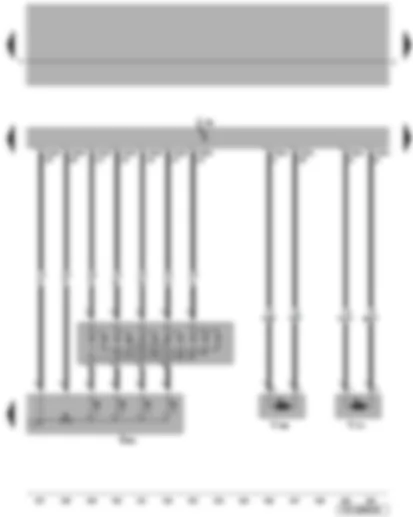
Wiring Diagram VW TRANSPORTER 2008 - Control unit for left seat - row 3 - control unit for heated left seat - row 3


Wiring Diagram  VW TRANSPORTER 2008 - Control unit for left seat - row 3 - control unit for heated left seat - row 3 https://portal-diagnostov.com/license.html
https://portal-diagnostov.com/license.html Automotive Electricians Portal FZCO Automotive Electricians Portal FZCO
Get access to all wiring diagrams of the carDownload PDF file
G534Temperature sensor for left seat, row 3
J782Control unit for left seat, row 3
J783Control unit for heated left seat, row 3
N406Valve block for lumbar support adjustment for left seat, row 3
T2xj2-pin connector
T4xf4-pin connector
T6xr6-pin connector
T6xs6-pin connector
T20xc20-pin connector
V369Lumbar support adjustment pump for left seat, row 3
Z72Heated backrest for left seat, row 3
Z73Heated seat cushion for left seat, row 3
  136 Earth point, near rear left seat
  165 Earth connection 1, in rear seat adjustment wiring harness
  259 Earth connection 2, in optional equipment wiring harness

Wiring Diagram VW TRANSPORTER 2008 - Control unit for right seat - row 3


Wiring Diagram  VW TRANSPORTER 2008 - Control unit for right seat - row 3 https://portal-diagnostov.com/license.html
https://portal-diagnostov.com/license.html Automotive Electricians Portal FZCO Automotive Electricians Portal FZCO
Get access to all wiring diagrams of the carDownload PDF file
E549Backrest adjustment button for right seat, row 3
E558Depth adjustment button for right seat, row 3
E568Height adjustment button for front of right seat, row 3
E569Height adjustment button for rear of right seat, row 3
E570Head restraint adjustment button for right seat, row 3
E571Longitudinal adjustment button for right seat, row 3
J784Control unit for right seat, row 3
T20xd20-pin connector

Wiring Diagram VW TRANSPORTER 2008 - Height adjustment button for lumbar support of right seat - row 3 - control unit for right seat - row 3


Wiring Diagram  VW TRANSPORTER 2008 - Height adjustment button for lumbar support of right seat - row 3 - control unit for right seat - row 3 https://portal-diagnostov.com/license.html
https://portal-diagnostov.com/license.html Automotive Electricians Portal FZCO Automotive Electricians Portal FZCO
Get access to all wiring diagrams of the carDownload PDF file
E567Height adjustment button for lumbar support of right seat, row 3
J784Control unit for right seat, row 3
T20xd20-pin connector
T20xe20-pin connector
V361Backrest adjustment motor for right seat, row 3
V364height adjustment motor 2 for right seat, row 3

Wiring Diagram VW TRANSPORTER 2008 - Control unit for right seat - row 3


Wiring Diagram  VW TRANSPORTER 2008 - Control unit for right seat - row 3 https://portal-diagnostov.com/license.html
https://portal-diagnostov.com/license.html Automotive Electricians Portal FZCO Automotive Electricians Portal FZCO
Get access to all wiring diagrams of the carDownload PDF file
J784Control unit for right seat, row 3
T6xq6-pin connector
T20xe20-pin connector
V358height adjustment motor 1 for right seat, row 3
V359Head restraint adjustment motor for right seat, row 3
V360Longitudinal adjustment motor for right seat, row 3
V363Depth adjustment motor for right seat, row 3

Wiring Diagram VW TRANSPORTER 2008 - Control unit for right seat - row 3 - seat heating


Wiring Diagram  VW TRANSPORTER 2008 - Control unit for right seat - row 3 - seat heating https://portal-diagnostov.com/license.html
https://portal-diagnostov.com/license.html Automotive Electricians Portal FZCO Automotive Electricians Portal FZCO
Get access to all wiring diagrams of the carDownload PDF file
G535Temperature sensor for right seat, row 3
J784Control unit for right seat, row 3
J785Control unit for heated right seat, row 3
N407Valve block for lumbar support adjustment for right seat, row 3
T2xk2-pin connector
T4xg4-pin connector
T6xt6-pin connector
T6xu6-pin connector
T20xe20-pin connector
V362Lumbar support adjustment pump for right seat, row 3
Z74Heated backrest for right seat, row 3
Z75Heated seat cushion for right seat, row 3
  96 Earth point, near rear left seat
  166 Earth connection 2, in rear seat adjustment wiring harness
  454 Earth connection 4, in optional equipment wiring harness

Wiring Diagram VW TRANSPORTER 2008 - Control unit for left seat - row 2 - seat heating


Wiring Diagram  VW TRANSPORTER 2008 - Control unit for left seat - row 2 - seat heating https://portal-diagnostov.com/license.html
https://portal-diagnostov.com/license.html Automotive Electricians Portal FZCO Automotive Electricians Portal FZCO
Get access to all wiring diagrams of the carDownload PDF file
G528Potentiometer for heated left seat, row 2
G532Temperature sensor for left seat, row 2
J158Control unit for heated left seat, row 2
J779Control unit for left seat, row 2
T2xm2-pin connector
T6xx6-pin connector
T8xk8-pin connector
T12xr12-pin connector
Z68Heated backrest for left seat, row 2
Z69Heated seat cushion for left seat, row 2
  291 Earth connection 2, in second battery wiring harness
  M63 Connection 3, in rear seat wiring harness
  M64 Connection 4, in rear seat wiring harness
  O14 Connection 3, in seat heating wiring harness
  O15 Connection 4, in seat heating wiring harness

Wiring Diagram VW TRANSPORTER 2008 - Control unit for left seat - row 2


Wiring Diagram  VW TRANSPORTER 2008 - Control unit for left seat - row 2 https://portal-diagnostov.com/license.html
https://portal-diagnostov.com/license.html Automotive Electricians Portal FZCO Automotive Electricians Portal FZCO
Get access to all wiring diagrams of the carDownload PDF file
E543Height adjustment button for front of left seat, row 2
E544Height adjustment button for rear of left seat, row 2
E545Head restraint adjustment button for left seat, row 2
E546Longitudinal adjustment button for left seat, row 2
E547Backrest adjustment button for left seat, row 2
E548Depth adjustment button for left seat, row 2
J779Control unit for left seat, row 2
T2xl2-pin connector
T12xr12-pin connector
T20xf20-pin connector

Wiring Diagram VW TRANSPORTER 2008 - Control unit for left seat - row 2


Wiring Diagram  VW TRANSPORTER 2008 - Control unit for left seat - row 2 https://portal-diagnostov.com/license.html
https://portal-diagnostov.com/license.html Automotive Electricians Portal FZCO Automotive Electricians Portal FZCO
Get access to all wiring diagrams of the carDownload PDF file
E542Height adjustment button for lumbar support of left seat, row 2
J779Control unit for left seat, row 2
T20xf20-pin connector
T20xg20-pin connector
V346Backrest adjustment motor for left seat, row 2
V350Height adjustment motor 2 for left seat, row 2

Wiring Diagram VW TRANSPORTER 2008 - Control unit for left seat - row 2


Wiring Diagram  VW TRANSPORTER 2008 - Control unit for left seat - row 2 https://portal-diagnostov.com/license.html
https://portal-diagnostov.com/license.html Automotive Electricians Portal FZCO Automotive Electricians Portal FZCO
Get access to all wiring diagrams of the carDownload PDF file
E550End switch for adjustable left seat, row 2
J779Control unit for left seat, row 2
T20xg20-pin connector
V348Depth adjustment motor for left seat, row 2
V349Height adjustment motor 1 for left seat, row 2
V372Head restraint adjustment motor for left seat, row 2
V373Longitudinal adjustment motor for left seat, row 2

Wiring Diagram VW TRANSPORTER 2008 - Control unit for left seat - row 2 - valve block for lumbar support adjustment for left seat - row 2


Wiring Diagram  VW TRANSPORTER 2008 - Control unit for left seat - row 2 - valve block for lumbar support adjustment for left seat - row 2 https://portal-diagnostov.com/license.html
https://portal-diagnostov.com/license.html Automotive Electricians Portal FZCO Automotive Electricians Portal FZCO
Get access to all wiring diagrams of the carDownload PDF file
J779Control unit for left seat, row 2
N404Valve block for lumbar support adjustment for left seat, row 2
T6xv6-pin connector
T6xy6-pin connector
T12xr12-pin connector
T20xg20-pin connector
T42xa42-pin connector
V347Lumbar support adjustment pump for left seat, row 2
  412 Earth connection 3, in seat adjuster wiring harness
  X54 Positive connection (58), in optional equipment wiring harness

Wiring Diagram VW TRANSPORTER 2008 - Control unit for right seat - row 2 - heated seat cushion for right seat - row 2


Wiring Diagram  VW TRANSPORTER 2008 - Control unit for right seat - row 2 - heated seat cushion for right seat - row 2 https://portal-diagnostov.com/license.html
https://portal-diagnostov.com/license.html Automotive Electricians Portal FZCO Automotive Electricians Portal FZCO
Get access to all wiring diagrams of the carDownload PDF file
G529Potentiometer for heated right seat, row 2
G533Temperature sensor for right seat, row 2
J780Control unit for heated right seat, row 2
J781Control unit for right seat, row 2
T2xn2-pin connector
T6xz6-pin connector
T8xl8-pin connector
T12xs12-pin connector
Z70Heated backrest for right seat, row 2
Z71Heated seat cushion for right seat, row 2
  M65 Connection 5, in rear seat wiring harness
  M66 Connection 6, in rear seat wiring harness
  O12 Connection 1, in seat heating wiring harness
  O13 Connection 2, in seat heating wiring harness

Wiring Diagram VW TRANSPORTER 2008 - Seat longitudinal adjustment button - control unit for right seat - row 2


Wiring Diagram  VW TRANSPORTER 2008 - Seat longitudinal adjustment button - control unit for right seat - row 2 https://portal-diagnostov.com/license.html
https://portal-diagnostov.com/license.html Automotive Electricians Portal FZCO Automotive Electricians Portal FZCO
Get access to all wiring diagrams of the carDownload PDF file
E552Height adjustment button for front of right seat, row 2
E553Height adjustment button for rear of right seat, row 2
E554Head restraint adjustment button for right seat, row 2
E555Longitudinal adjustment button for right seat, row 2
E556Backrest adjustment button for right seat, row 2
E557Depth adjustment button for right seat, row 2
J781Control unit for right seat, row 2
T2xl2-pin connector
T12xs12-pin connector
T20xh20-pin connector

Wiring Diagram VW TRANSPORTER 2008 - Height adjustment button for lumbar support of right seat - row 2 - control unit for right seat - row 2


Wiring Diagram  VW TRANSPORTER 2008 - Height adjustment button for lumbar support of right seat - row 2 - control unit for right seat - row 2 https://portal-diagnostov.com/license.html
https://portal-diagnostov.com/license.html Automotive Electricians Portal FZCO Automotive Electricians Portal FZCO
Get access to all wiring diagrams of the carDownload PDF file
E551Height adjustment button for lumbar support of right seat, row 2
J781Control unit for right seat, row 2
T20xh20-pin connector
T20xi20-pin connector
V353Backrest adjustment motor for right seat, row 2
V357height adjustment motor 2 for right seat, row 2

Wiring Diagram VW TRANSPORTER 2008 - Control unit for right seat - row 2


Wiring Diagram  VW TRANSPORTER 2008 - Control unit for right seat - row 2 https://portal-diagnostov.com/license.html
https://portal-diagnostov.com/license.html Automotive Electricians Portal FZCO Automotive Electricians Portal FZCO
Get access to all wiring diagrams of the carDownload PDF file
E559End switch for adjustable right seat, row 2
J781Control unit for right seat, row 2
T20xi20-pin connector
V351Head restraint adjustment motor for right seat, row 2
V352Longitudinal adjustment motor for right seat, row 2
V355Depth adjustment motor for right seat, row 2
V356height adjustment motor 1 for right seat, row 2

Wiring Diagram VW TRANSPORTER 2008 - Control unit for right seat - row 2 - valve block for lumbar support adjustment for right seat - row 2


Wiring Diagram  VW TRANSPORTER 2008 - Control unit for right seat - row 2 - valve block for lumbar support adjustment for right seat - row 2 https://portal-diagnostov.com/license.html
https://portal-diagnostov.com/license.html Automotive Electricians Portal FZCO Automotive Electricians Portal FZCO
Get access to all wiring diagrams of the carDownload PDF file
J781Control unit for right seat, row 2
N405Valve block for lumbar support adjustment for right seat, row 2
T6ya6-pin connector
T6yb6-pin connector
T12xs12-pin connector
T20xi20-pin connector
V354Lumbar support adjustment pump for right seat, row 2
  413 Earth connection 4, in seat adjuster wiring harness

Wiring Diagram VW TRANSPORTER 2008 - Footwell light


Wiring Diagram  VW TRANSPORTER 2008 - Footwell light https://portal-diagnostov.com/license.html
https://portal-diagnostov.com/license.html Automotive Electricians Portal FZCO Automotive Electricians Portal FZCO
Get access to all wiring diagrams of the carDownload PDF file
E390Interior lighting central switch button
L106Rear left footwell illumination bulb
L107Rear right footwell illumination bulb
L151Front left footwell illumination bulb
L152Front right footwell illumination bulb
SC17Fuse 17 on fuse holder C
T2xo2-pin connector
T2xp2-pin connector
T10ab10-pin connector, white, coupling station on left of A-pillar
T12xr12-pin connector
T12xs12-pin connector
W14Front passenger side illuminated vanity mirror
W20Driver side illuminated vanity mirror
  402 Earth connection (interior light), in interior wiring harness
  B315 Positive connection 1 (30a), in main wiring harness
  B433 Connection (footwell light), in main wiring harness
  M61 Connection 1, in rear seat wiring harness
  M62 Connection 2, in rear seat wiring harness
  R6 Positive connection 1, in interior light wiring harness

Wiring Diagram VW TRANSPORTER 2008 - Electric folding table button - digital sound package amplifier - folding table motor


Wiring Diagram  VW TRANSPORTER 2008 - Electric folding table button - digital sound package amplifier - folding table motor https://portal-diagnostov.com/license.html
https://portal-diagnostov.com/license.html Automotive Electricians Portal FZCO Automotive Electricians Portal FZCO
Get access to all wiring diagrams of the carDownload PDF file
E498Electric folding table button
R184Digital sound package amplifier
T1xcSingle connector
T1xdSingle connector
T1xeSingle connector
T6xc6-pin connector
T6yc6-pin connector
T6yd6-pin connector
T10xc10-pin connector
T42xa42-pin connector
V250Folding table motor

Wiring Diagram VW TRANSPORTER 2008 - Control unit with display for radio and navigation - loudspeaker switch-off relay - digital sound package amplifier


Wiring Diagram  VW TRANSPORTER 2008 - Control unit with display for radio and navigation - loudspeaker switch-off relay - digital sound package amplifier https://portal-diagnostov.com/license.html
https://portal-diagnostov.com/license.html Automotive Electricians Portal FZCO Automotive Electricians Portal FZCO
Get access to all wiring diagrams of the carDownload PDF file
J503Control unit with display for radio and navigation system
J639Loudspeaker switch-off relay
R184Digital sound package amplifier
T6yd6-pin connector
T8m8-pin connector
T8xm8-pin connector
T10xd10-pin connector
T12xu12-pin connector
  133 Earth connection, in loudspeaker wiring harness

Wiring Diagram VW TRANSPORTER 2008 - Loudspeaker switch-off relay - voice amplification control unit


Wiring Diagram  VW TRANSPORTER 2008 - Loudspeaker switch-off relay - voice amplification control unit https://portal-diagnostov.com/license.html
https://portal-diagnostov.com/license.html Automotive Electricians Portal FZCO Automotive Electricians Portal FZCO
Get access to all wiring diagrams of the carDownload PDF file
J639Loudspeaker switch-off relay
K00589850810#BTJ656">J656K00589850810#BTJ656">Voice amplification control unitK00589850810#BTJ656
T8xn8-pin connector
T12xu12-pin connector
T24e24-pin connector


VW TRANSPORTER 2008


VW TRANSPORTER 2008 Overview:

Overview:
   
VW TRANSPORTER 2008 Overview: https://portal-diagnostov.com/license.html
https://portal-diagnostov.com/license.html Automotive Electricians Portal FZCO Automotive Electricians Portal FZCO
Get access to all wiring diagrams of the carDownload PDF file
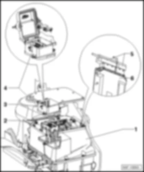
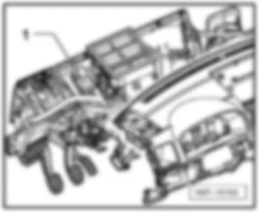
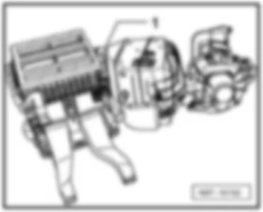
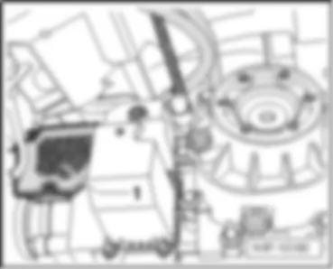
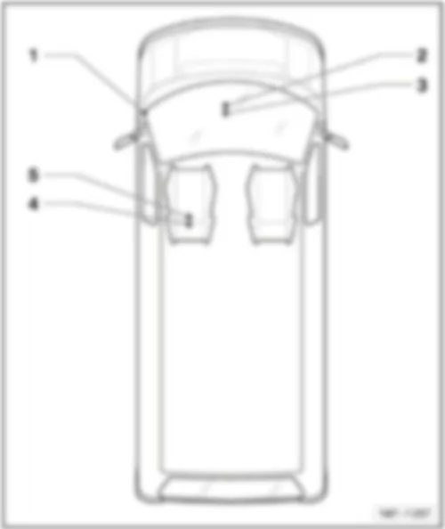
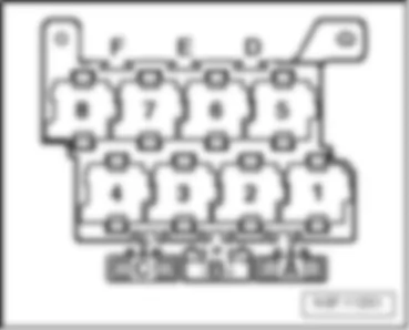
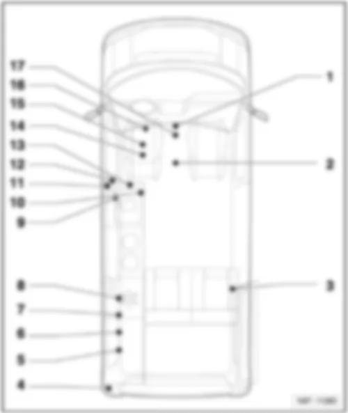
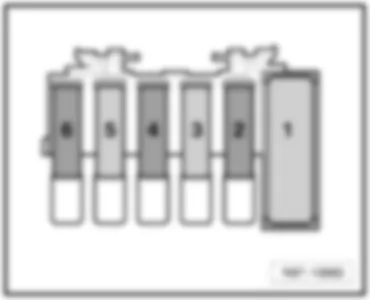
1 -  Relay carrier electronics box
2 -  Relay carrier 1, cockpit
3 -  Relay carrier 2, cockpit
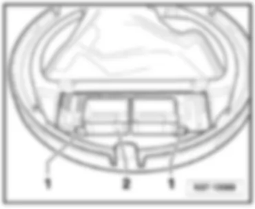
4 -  Relay carrier on left of seat box
  Note
The chamber marked as “vacant” can be fitted with a relay or a pin connector. See Fitting Locations "interior single fuses" and "coupling station"!

   
No.   Function/component   Location   Figure on page
1 - Battery isolation relay -J7-
from February 2004
from June 2004
from August 2006
from June 2007
2 - Auxiliary heater relay -J8-
from February 2004
from June 2004
from August 2006
from June 2007
3 - Fuel pump relay -J17-
from June 2004
from August 2006
from June 2007
from November 2007
      - Relay carrier electronics box (2.0 l - petrol engine) ----- from March 2003
from June 2004
from August 2006
from June 2007
from November 2007
      - Relay carrier electronics box (2,5 l - diesel engine) ----- from March 2003
from June 2004
from August 2006
from June 2007
from November 2007
      - Relay carrier electronics box (3,2 l - petrol engine) ----- from March 2003
from June 2004
from August 2006
from June 2007
from November 2007
4 - Headlight washer system relay -J39-
from February 2004
from June 2004
from August 2006
from June 2007
5 - Electric fuel pump 2 relay -J49- - Relay carrier electronics box (2.0 l - petrol engine) ----- from March 2003
from June 2004
from August 2006
from June 2007
from November 2007
      - Relay carrier electronics box (3,2 l - petrol engine) ----- from March 2003
from June 2004
from August 2006
from June 2007
from November 2007
6 - Glow plug relay -J52-
from June 2004
from August 2006
from June 2007
from November 2007
      - Relay carrier electronics box (2,5 l - diesel engine) ----- from March 2003
from June 2004
from August 2006
from June 2007
from November 2007
7 - X-contact relief relay -J59-
from February 2004
from June 2004
from August 2006
from June 2007
8 - Automatic gearbox relay -J60-
      - Relay carrier electronics box (2.0 l - petrol engine) - from March 2003
      - Relay carrier electronics box (2,5 l - diesel engine) ----- from March 2003
from June 2004
from August 2006
from June 2007
from November 2007
      - Relay carrier electronics box (3,2 l - petrol engine) ----- from March 2003
from June 2004
from August 2006
from June 2007
from November 2007
9 - Alarm system control unit -J85-
from June 2004
from August 2006
from June 2007
10 - Magnetic clutch control unit -J153-
from June 2004
from August 2006
from June 2007
from November 2007
      - Relay carrier electronics box (2.0 l - petrol engine) ----- from March 2003
from June 2004
from August 2006
from June 2007
from November 2007
      - Relay carrier electronics box (3,2 l - petrol engine) ----- from March 2003
from June 2004
from August 2006
from June 2007
from November 2007
11 - Rear fresh air blower relay -J163-
from February 2004
from June 2004
12 - Automatic glow period control unit -J179- - Relay carrier electronics box (1.9 l - diesel engine) ---- from June 2004
from August 2006
from June 2007
from November 2007
      - Relay carrier electronics box (2,5 l - diesel engine) ---- from June 2004
from August 2006
from June 2007
from November 2007
13 - Switch-over relay 1 for roof ventilator -J180-
from February 2004
from June 2004
from August 2006
from June 2007
14 - Switch-over relay 2 for roof ventilator -J181-
from February 2004
from June 2004
from August 2006
from June 2007
15 - Differential lock control unit -J187-
from February 2004
from June 2004
from August 2006
from June 2007
16 - Starter inhibitor relay -J207- - Relay carrier electronics box (1.9 l - diesel engine) ---- from June 2004
from August 2006
from June 2007
from November 2007
      - Relay carrier electronics box (2.0 l - petrol engine) ---- from June 2004
from August 2006
from June 2007
from November 2007
      - Relay carrier electronics box (2,5 l - diesel engine) ----- from March 2003
from June 2004
from August 2006
from June 2007
from November 2007
      - Relay carrier electronics box (3,2 l - petrol engine) ----- from March 2003
from June 2004
from August 2006
from June 2007
from November 2007
17 - Cut-out relay for air conditioning system magnetic coupling -J246-
from June 2004
from August 2006
from June 2007
from November 2007
      - Relay carrier electronics box (2.0 l - petrol engine) ----- from March 2003
from June 2004
from August 2006
from June 2007
from November 2007
      - Relay carrier electronics box (3,2 l - petrol engine) ----- from March 2003
from June 2004
from August 2006
from June 2007
from November 2007
18 - Secondary air pump relay -J299- - Relay carrier electronics box (2.0 l - petrol engine) ----- from March 2003
from June 2004
from August 2006
from June 2007
from November 2007
      - Relay carrier electronics box (3,2 l - petrol engine) ----- from March 2003
from June 2004
from August 2006
from June 2007
from November 2007
19 - Terminal 30 voltage supply relay -J317-
from June 2004
from August 2006
from June 2007
from November 2007
      - Relay carrier electronics box (2.0 l - petrol engine) ----- from March 2003
from June 2004
from August 2006
from June 2007
from November 2007
      - Relay carrier electronics box (2,5 l - diesel engine) ----- from March 2003
from June 2004
from August 2006
from June 2007
from November 2007
      - Relay carrier electronics box (3,2 l - petrol engine) ----- from March 2003
from June 2004
from August 2006
from June 2007
from November 2007
20 - Rotating light relay -J326-
      - Relay carrier (2), cockpit -- from February 2004
from June 2004
      - Relay carrier on left of seat box -- from August 2006
from June 2007
21 - Folding exterior mirror control unit -J351- - Relay carrier (2), cockpit -- from August 2006
from June 2007
22 - Brake light additional relay -J419-
from February 2004
from June 2004
from August 2006
from June 2007
23 - Taxi alarm system 2 control unit -J430- - Relay carrier (2), cockpit ---- from February 2004
from June 2004
from August 2006
from June 2007
24 - Multifunction steering wheel control unit -J453-
from February 2004
from June 2004
from August 2006
from June 2007
25 - Alarm system relay 1 -J460- - Relay carrier (2), cockpit -- from February 2004
from June 2004
      - Relay carrier on left of seat box -- from August 2006
from June 2007
26 - Fresh air blower isolation relay -J487-
from February 2004
from June 2004
      - Relay carrier (2), cockpit --- from January 2006
from August 2006
from June 2007
27 - Auxiliary coolant heater relay -J493-
from February 2004
from June 2004
from August 2006
from June 2007
28 - Additional coolant pump relay -J496-
from June 2004
from August 2006
from June 2007
from November 2007
      - Relay carrier electronics box (2.0 l - petrol engine) ----- from March 2003
from June 2004
from August 2006
from June 2007
from November 2007
      - Relay carrier electronics box (2,5 l - diesel engine) ----- from March 2003
from June 2004
from August 2006
from June 2007
from November 2007
      - Relay carrier electronics box (3,2 l - petrol engine) ----- from March 2003
from June 2004
from August 2006
from June 2007
from November 2007
29 - Power steering control unit -J500-
      - Relay carrier electronics box (2.0 l - petrol engine) - from March 2003
      - Relay carrier electronics box (2,5 l - diesel engine) - from March 2003
      - Relay carrier electronics box (3,2 l - petrol engine) - from March 2003
30 - Taxi alarm remote control, control unit -J601- - Relay carrier on left of seat box ---- from February 2004
from June 2004
from August 2006
from June 2007
31 - Residual heat relay -J708-
from February 2004
from June 2004
from August 2006
from June 2007
32 - Dual signal inverter relay -J741-
      - Relay carrier (2), cockpit - from June 2003
      - Relay carrier (1), cockpit ---- from February 2004
from June 2004
from August 2006
from June 2007

   
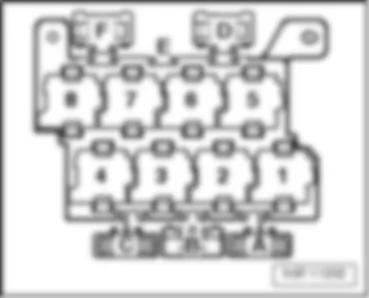
Relay carrier electronics box (8-pin), for 1.9 l diesel engine, from March 2003
t  In electronics box in engine compartment
For engine codes AXB and AXC
Pos. -  Connector/designation
1 -  Glow plug relay -J52-
2 -  Fuel pump relay -J17-
3 -  Magnetic clutch control unit -J153-
4 -  Cut-out relay for air conditioning system magnetic coupling -J246-
5 -  Vacant
6 -  Terminal 30 voltage supply relay -J317-
7 -  Additional coolant pump relay -J496-
8 -  Power steering control unit -J500-
2B -  Automatic gearbox relay -J60-
 
VW TRANSPORTER 2008 Overview: https://portal-diagnostov.com/license.html
https://portal-diagnostov.com/license.html Automotive Electricians Portal FZCO Automotive Electricians Portal FZCO
Get access to all wiring diagrams of the carDownload PDF file
Relay carrier electronics box (8-pin), for 1.9 l diesel engine, from June 2004
t  In electronics box in engine compartment
for engine codes AXB, AXC, BRR and BRS
Pos. -  Connector/designation
1 -  Glow plug relay -J52- (103) 2)
 -  Glow plug relay -J52- (100) 3)
 -  Automatic glow period control unit -J179- (457) 4)
2 -  Fuel pump relay -J17- (53)
 -  vacant1)
3 -  Magnetic clutch control unit -J153- (KL2)
4 -  Cut-out relay for air conditioning system magnetic coupling -J246- (53)
5 -  Fuel pump relay -J17- (53) 1)
6 -  Terminal 30 voltage supply relay -J317- (109)
7 -  Additional coolant pump relay -J496- (53)
8 -  Vacant
3C -  Starter inhibitor relay -J207- (53)
  Note
t  1) applicable from January 2006
t  2) for engine codes AXB and AXC only
t  3) applicable from June 2006 and engine codes AXB and AXC
t  4) for engine codes BRR and BRS only
 
VW TRANSPORTER 2008 Overview: https://portal-diagnostov.com/license.html
https://portal-diagnostov.com/license.html Automotive Electricians Portal FZCO Automotive Electricians Portal FZCO
Get access to all wiring diagrams of the carDownload PDF file
Relay carrier electronics box (8-pin), for 1.9 l diesel engine, from August 2006
t  In electronics box in engine compartment
for engine codes AXB, AXC, BRR and BRS
Pos. -  Connector/designation
1 -  Glow plug relay -J52- (100) 1)
 -  Automatic glow period control unit -J179- (457) 2)
2 -  Vacant
3 -  Magnetic clutch control unit -J153- (KL2)
4 -  Cut-out relay for air conditioning system magnetic coupling -J246- (53)
5 -  Fuel pump relay -J17- (53)
6 -  Terminal 30 voltage supply relay -J317- (109)
7 -  Additional coolant pump relay -J496- (53)
8 -  Vacant
3C -  Starter inhibitor relay -J207- (53)
  Note
t  1) for engine codes AXB and AXC only
t  2) for engine codes BRR and BRS only
 
VW TRANSPORTER 2008 Overview: https://portal-diagnostov.com/license.html
https://portal-diagnostov.com/license.html Automotive Electricians Portal FZCO Automotive Electricians Portal FZCO
Get access to all wiring diagrams of the carDownload PDF file
Relay carrier electronics box (8-pin), for 1.9 l diesel engine, from June 2007
t  In electronics box in engine compartment
for engine codes AXB, AXC, BRR and BRS
Pos. -  Connector/designation
1 -  Glow plug relay -J52- (100) 1)
 -  Automatic glow period control unit -J179- (457) 2)
2 -  Vacant
3 -  Magnetic clutch control unit -J153- (KL2)
4 -  Cut-out relay for air conditioning system magnetic coupling -J246- (53)
5 -  Fuel pump relay -J17- (53)
6 -  Terminal 30 voltage supply relay -J317- (109)
7 -  Additional coolant pump relay -J496- (53)
8 -  Vacant
3C -  Starter inhibitor relay -J207- (53)
  Note
t  1) for engine codes AXB and AXC only
t  2) for engine codes BRR and BRS only
 
VW TRANSPORTER 2008 Overview: https://portal-diagnostov.com/license.html
https://portal-diagnostov.com/license.html Automotive Electricians Portal FZCO Automotive Electricians Portal FZCO
Get access to all wiring diagrams of the carDownload PDF file
Relay carrier electronics box (8-pin), for 1.9 l diesel engine, from November 2007
t  In electronics box in engine compartment
for engine codes AXB, AXC, BRR and BRS
Pos. -  Connector/designation
1 -  Glow plug relay -J52- (100) 1)
 -  Automatic glow period control unit -J179- (457) 2)
2 -  Vacant
3 -  Magnetic clutch control unit -J153- (454)
4 -  Vacant
5 -  Vacant
 -  Starter inhibitor relay -J207- (449)
6 -  Terminal 30 voltage supply relay -J317- (643)
7 -  Fuel pump relay -J17- (449)
 -  Additional coolant pump relay -J496- (449)
8 -  Vacant
 -  Cut-out relay for air conditioning system magnetic coupling -J246- (449)
  Note
t  1) for engine codes AXB and AXC only
t  2) for engine codes BRR and BRS only
 
VW TRANSPORTER 2008 Overview: https://portal-diagnostov.com/license.html
https://portal-diagnostov.com/license.html Automotive Electricians Portal FZCO Automotive Electricians Portal FZCO
Get access to all wiring diagrams of the carDownload PDF file
Relay carrier electronics box (8-pin), for 2.0 l petrol engine, from March 2003
t  In electronics box in engine compartment
For engine code AXA
Pos. -  Connector/designation
1 -  Secondary air pump relay -J299-
2 -  Fuel pump relay -J17-
3 -  Magnetic clutch control unit -J153-
4 -  Cut-out relay for air conditioning system magnetic coupling -J246-
5 -  Electric fuel pump 2 relay -J49-
6 -  Terminal 30 voltage supply relay -J317-
7 -  Additional coolant pump relay -J496-
8 -  Power steering control unit -J500-
2B -  Automatic gearbox relay -J60-
 
VW TRANSPORTER 2008 Overview: https://portal-diagnostov.com/license.html
https://portal-diagnostov.com/license.html Automotive Electricians Portal FZCO Automotive Electricians Portal FZCO
Get access to all wiring diagrams of the carDownload PDF file
Relay carrier electronics box (8-pin), for 2.0 l petrol engine, from June 2004
t  In electronics box in engine compartment
For engine code AXA
Pos. -  Connector/designation
1 -  Secondary air pump relay -J299- (100)
2 -  Fuel pump relay -J17- (167)
3 -  Magnetic clutch control unit -J153- (KL2)
4 -  Cut-out relay for air conditioning system magnetic coupling -J246- (53)
5 -  Electric fuel pump 2 relay -J49- (404)
6 -  Terminal 30 voltage supply relay -J317- (109)
7 -  Additional coolant pump relay -J496- (53)
8 -  Vacant
3C -  Starter inhibitor relay -J207- (53)
 
VW TRANSPORTER 2008 Overview: https://portal-diagnostov.com/license.html
https://portal-diagnostov.com/license.html Automotive Electricians Portal FZCO Automotive Electricians Portal FZCO
Get access to all wiring diagrams of the carDownload PDF file
Relay carrier electronics box (8-pin), for 2.0 l petrol engine, from August 2006
t  In electronics box in engine compartment
For engine code AXA
Pos. -  Connector/designation
1 -  Secondary air pump relay -J299- (100)
2 -  Fuel pump relay -J17- (167)
3 -  Magnetic clutch control unit -J153- (KL2)
4 -  Cut-out relay for air conditioning system magnetic coupling -J246- (53)
5 -  Electric fuel pump 2 relay -J49- (404)
6 -  Terminal 30 voltage supply relay -J317- (109)
7 -  Additional coolant pump relay -J496- (53)
8 -  Vacant
3C -  Starter inhibitor relay -J207- (53)
 
VW TRANSPORTER 2008 Overview: https://portal-diagnostov.com/license.html
https://portal-diagnostov.com/license.html Automotive Electricians Portal FZCO Automotive Electricians Portal FZCO
Get access to all wiring diagrams of the carDownload PDF file
Relay carrier electronics box (8-pin), for 2.0 l petrol engine, from June 2007
t  In electronics box in engine compartment
For engine code AXA
Pos. -  Connector/designation
1 -  Secondary air pump relay -J299- (100)
2 -  Fuel pump relay -J17- (167)
3 -  Magnetic clutch control unit -J153- (KL2)
4 -  Cut-out relay for air conditioning system magnetic coupling -J246- (53)
5 -  Electric fuel pump 2 relay -J49- (404)
6 -  Terminal 30 voltage supply relay -J317- (109)
7 -  Additional coolant pump relay -J496- (53)
8 -  Vacant
3C -  Starter inhibitor relay -J207- (53)
 
VW TRANSPORTER 2008 Overview: https://portal-diagnostov.com/license.html
https://portal-diagnostov.com/license.html Automotive Electricians Portal FZCO Automotive Electricians Portal FZCO
Get access to all wiring diagrams of the carDownload PDF file
Relay carrier electronics box (8-pin), for 2.0 l petrol engine, from November 2007
t  In electronics box in engine compartment
For engine code AXA
Pos. -  Connector/designation
1 -  Secondary air pump relay -J299- (100)
2 -  Vacant
 -  Electric fuel pump 2 relay -J49- (449)
3 -  Magnetic clutch control unit -J153- (454)
4 -  Fuel pump relay -J17- (643)
5 -  Vacant
 -  Starter inhibitor relay -J207- (449)
6 -  Terminal 30 voltage supply relay -J317- (643)
7 -  Vacant
 -  Additional coolant pump relay -J496- (449)
8 -  Vacant
 -  Cut-out relay for air conditioning system magnetic coupling -J246- (449)
 
VW TRANSPORTER 2008 Overview: https://portal-diagnostov.com/license.html
https://portal-diagnostov.com/license.html Automotive Electricians Portal FZCO Automotive Electricians Portal FZCO
Get access to all wiring diagrams of the carDownload PDF file
Relay carrier electronics box (8-pin), for 2,5 l diesel engine, from March 2003
t  In electronics box in engine compartment
For engine codes AXD and AXE
Pos. -  Connector/designation
1 -  Glow plug relay -J52-
2 -  Fuel pump relay -J17-
3 -  Vacant
4 -  Starter inhibitor relay -J207-
5 -  Vacant
6 -  Terminal 30 voltage supply relay -J317-
7 -  Additional coolant pump relay -J496-
8 -  Power steering control unit -J500-
2B -  Automatic gearbox relay -J60-
 
VW TRANSPORTER 2008 Overview: https://portal-diagnostov.com/license.html
https://portal-diagnostov.com/license.html Automotive Electricians Portal FZCO Automotive Electricians Portal FZCO
Get access to all wiring diagrams of the carDownload PDF file
Relay carrier electronics box (8-pin), for 2,5 l diesel engine, from June 2004
t  In electronics box in engine compartment
for engine codes AXD, AXE, BLJ, BNZ and BPC
Pos. -  Connector/designation
1 -  Glow plug relay -J52- (103) 2)
 -  Glow plug relay -J52- (100) 3)
 -  Automatic glow period control unit -J179- (475) 4)
2 -  Fuel pump relay -J17- (53)
3 -  Vacant
4 -  Vacant
5 -  Fuel pump relay -J17- (53) 1)
6 -  Terminal 30 voltage supply relay -J317- (109)
7 -  Additional coolant pump relay -J496- (53)
8 -  Vacant
2B -  Automatic gearbox relay -J60- (53)
3C -  Starter inhibitor relay -J207- (53)
  Note
t  1) applicable from January 2006
t  2) for engine codes AXD, AXE and BLJ only
t  3) applicable from June 2006 and engine codes AXD, AXE, BLJ
t  4) for engine codes BNZ and BPC only
 
VW TRANSPORTER 2008 Overview: https://portal-diagnostov.com/license.html
https://portal-diagnostov.com/license.html Automotive Electricians Portal FZCO Automotive Electricians Portal FZCO
Get access to all wiring diagrams of the carDownload PDF file
Relay carrier electronics box (8-pin), for 2,5 l diesel engine, from August 2006
t  In electronics box in engine compartment
for engine codes AXD, AXE, BLJ, BNZ and BPC
Pos. -  Connector/designation
1 -  Glow plug relay -J52- (100) 1)
 -  Automatic glow period control unit -J179- (475) 2)
2 -  Vacant
3 -  Vacant
4 -  Vacant
5 -  Fuel pump relay -J17- (53)
6 -  Terminal 30 voltage supply relay -J317- (109)
7 -  Additional coolant pump relay -J496- (53)
8 -  Vacant
2B -  Automatic gearbox relay -J60- (53)
3C -  Starter inhibitor relay -J207- (53)
  Note
t  1) for engine codes AXD, AXE and BJL only
t  2) for engine codes BNZ and BPC only
 
VW TRANSPORTER 2008 Overview: https://portal-diagnostov.com/license.html
https://portal-diagnostov.com/license.html Automotive Electricians Portal FZCO Automotive Electricians Portal FZCO
Get access to all wiring diagrams of the carDownload PDF file
Relay carrier electronics box (8-pin), for 2,5 l diesel engine, from June 2007
t  In electronics box in engine compartment
for engine codes AXD, AXE, BLJ, BNZ and BPC
Pos. -  Connector/designation
1 -  Glow plug relay -J52- (100) 1)
 -  Automatic glow period control unit -J179- (475) 2)
2 -  Vacant
3 -  Vacant
4 -  Vacant
5 -  Fuel pump relay -J17- (53)
6 -  Terminal 30 voltage supply relay -J317- (109)
7 -  Additional coolant pump relay -J496- (53)
8 -  Vacant
2B -  Automatic gearbox relay -J60- (53)
3C -  Starter inhibitor relay -J207- (53)
  Note
t  1) for engine codes AXD, AXE and BLJ only
t  2) for engine codes BNZ and BPC only
 
VW TRANSPORTER 2008 Overview: https://portal-diagnostov.com/license.html
https://portal-diagnostov.com/license.html Automotive Electricians Portal FZCO Automotive Electricians Portal FZCO
Get access to all wiring diagrams of the carDownload PDF file
Relay carrier electronics box (8-pin), for 2,5 l diesel engine, from November 2007
t  In electronics box in engine compartment
for engine codes AXD, AXE, BLJ, BNZ and BPC
Pos. -  Connector/designation
1 -  Glow plug relay -J52- (100) 1)
 -  Automatic glow period control unit -J179- (475) 2)
2 -  Vacant
3 -  Vacant
4 -  Vacant
5 -  Automatic gearbox relay -J60- (449)
 -  Starter inhibitor relay -J207- (449)
6 -  Terminal 30 voltage supply relay -J317- (643)
7 -  Fuel pump relay -J17- (449)
 -  Additional coolant pump relay -J496- (449)
8 -  Vacant
  Note
t  1) for engine codes AXD, AXE and BLJ only
t  2) for engine codes BNZ and BPC only
 
VW TRANSPORTER 2008 Overview: https://portal-diagnostov.com/license.html
https://portal-diagnostov.com/license.html Automotive Electricians Portal FZCO Automotive Electricians Portal FZCO
Get access to all wiring diagrams of the carDownload PDF file
Relay carrier electronics box (8-pin), for 3,2 l petrol engine, from March 2003
t  In electronics box in engine compartment
For engine codes BDL and BDM
Pos. -  Connector/designation
1 -  Secondary air pump relay -J299-
2 -  Terminal 30 voltage supply relay -J317-
3 -  Magnetic clutch control unit -J153-
4 -  Cut-out relay for air conditioning system magnetic coupling -J246-
5 -  Electric fuel pump 2 relay -J49-
 -  Additional coolant pump relay -J496-
6 -  Fuel pump relay -J17-
7 -  Starter inhibitor relay -J207-
8 -  Power steering control unit -J500-
2B -  Automatic gearbox relay -J60-
 
VW TRANSPORTER 2008 Overview: https://portal-diagnostov.com/license.html
https://portal-diagnostov.com/license.html Automotive Electricians Portal FZCO Automotive Electricians Portal FZCO
Get access to all wiring diagrams of the carDownload PDF file
Relay carrier electronics box (8-pin), for 3,2 l petrol engine, from June 2004
t  In electronics box in engine compartment
For engine codes BDL, BDM and BKK
Pos. -  Connector/designation
1 -  Secondary air pump relay -J299- (100)
2 -  Terminal 30 voltage supply relay -J317- (428)
 -  Terminal 30 voltage supply relay -J317- (614) 1)
3 -  Magnetic clutch control unit -J153- (KL2)
4 -  Cut-out relay for air conditioning system magnetic coupling -J246- (53)
5 -  Electric fuel pump 2 relay -J49- (404)
 -  Additional coolant pump relay -J496- (404)
6 -  Fuel pump relay -J17- (167)
7 -  Vacant
8 -  Vacant
2B -  Automatic gearbox relay -J60- (53)
3C -  Starter inhibitor relay -J207- (53)
  Note
1) applicable from June 2006
 
VW TRANSPORTER 2008 Overview: https://portal-diagnostov.com/license.html
https://portal-diagnostov.com/license.html Automotive Electricians Portal FZCO Automotive Electricians Portal FZCO
Get access to all wiring diagrams of the carDownload PDF file
Relay carrier electronics box (8-pin), for 3,2 l petrol engine, from August 2006
t  In electronics box in engine compartment
For engine codes BDL, BDM and BKK
Pos. -  Connector/designation
1 -  Secondary air pump relay -J299- (100)
2 -  Terminal 30 voltage supply relay -J317- (614)
3 -  Magnetic clutch control unit -J153- (KL2)
4 -  Cut-out relay for air conditioning system magnetic coupling -J246- (53)
5 -  Electric fuel pump 2 relay -J49- (404)
 -  Additional coolant pump relay -J496- (404)
6 -  Fuel pump relay -J17- (167)
7 -  Vacant
8 -  Vacant
2B -  Automatic gearbox relay -J60- (53)
3C -  Starter inhibitor relay -J207- (53)
 
VW TRANSPORTER 2008 Overview: https://portal-diagnostov.com/license.html
https://portal-diagnostov.com/license.html Automotive Electricians Portal FZCO Automotive Electricians Portal FZCO
Get access to all wiring diagrams of the carDownload PDF file
Relay carrier electronics box (8-pin), for 3,2 l petrol engine, from June 2007
t  In electronics box in engine compartment
For engine codes BDL, BDM and BKK
Pos. -  Connector/designation
1 -  Secondary air pump relay -J299- (100)
2 -  Terminal 30 voltage supply relay -J317- (614)
3 -  Magnetic clutch control unit -J153- (KL2)
4 -  Cut-out relay for air conditioning system magnetic coupling -J246- (53)
5 -  Electric fuel pump 2 relay -J49- (404)
 -  Additional coolant pump relay -J496- (404)
6 -  Fuel pump relay -J17- (167)
7 -  Vacant
8 -  Vacant
2B -  Automatic gearbox relay -J60- (53)
3C -  Starter inhibitor relay -J207- (53)
 
VW TRANSPORTER 2008 Overview: https://portal-diagnostov.com/license.html
https://portal-diagnostov.com/license.html Automotive Electricians Portal FZCO Automotive Electricians Portal FZCO
Get access to all wiring diagrams of the carDownload PDF file
Relay carrier electronics box (8-pin), for 3,2 l petrol engine, from November 2007
t  In electronics box in engine compartment
For engine codes BDL, BDM and BKK
Pos. -  Connector/designation
1 -  Secondary air pump relay -J299- (100)
2 -  Additional coolant pump relay -J496- (449)
 -  Electric fuel pump 2 relay -J49- (449)
3 -  Magnetic clutch control unit -J153- (454)
4 -  Vacant
5 -  Automatic gearbox relay -J60- (449)
 -  Starter inhibitor relay -J207- (449)
6 -  Terminal 30 voltage supply relay -J317- (100)
7 -  Fuel pump relay -J17- (643)
8 -  Vacant
 -  Cut-out relay for air conditioning system magnetic coupling -J246- (449)
 
VW TRANSPORTER 2008 Overview: https://portal-diagnostov.com/license.html
https://portal-diagnostov.com/license.html Automotive Electricians Portal FZCO Automotive Electricians Portal FZCO
Get access to all wiring diagrams of the carDownload PDF file
Relay carrier, left in seat box (8-pin), from March 2003
t  On left in seat box
Pos. -  Connector/designation
1 -  Vacant
2 -  Vacant
3 -  Vacant
4 -  Vacant
5 -  Vacant
6 -  vacant1)
 -  Battery isolation relay -J7-2)
7 -  Vacant
8 -  Battery isolation relay -J7-1)
 -  vacant2)
3) -  Dual signal inverter relay -J741-1)
  Note
t  1) applicable up to May 2003
t  2) applicable from June 2003
t  3) position is depends on equipment
 
VW TRANSPORTER 2008 Overview: https://portal-diagnostov.com/license.html
https://portal-diagnostov.com/license.html Automotive Electricians Portal FZCO Automotive Electricians Portal FZCO
Get access to all wiring diagrams of the carDownload PDF file
Relay carrier, left in seat box (8-pin), from February 2004
t  On left in seat box
Pos. -  Connector/designation
1 -  Vacant
2 -  Vacant
3 -  Vacant
4 -  Taxi alarm remote control, control unit -J601-1)
5 -  Vacant
6 -  Battery isolation relay -J7-
7 -  Vacant
8 -  Vacant
  Note
1) for models with taxi equipment only
 
VW TRANSPORTER 2008 Overview: https://portal-diagnostov.com/license.html
https://portal-diagnostov.com/license.html Automotive Electricians Portal FZCO Automotive Electricians Portal FZCO
Get access to all wiring diagrams of the carDownload PDF file
Relay carrier, left in seat box (8-pin), from June 2004
t  On left in seat box
Pos. -  Connector/designation
1 -  Vacant
2 -  Vacant
3 -  Vacant
4 -  Taxi alarm remote control, control unit -J601-1)
5 -  Vacant
6 -  Battery isolation relay -J7- (100)
7 -  Vacant
8 -  Vacant
  Note
1) for models with taxi equipment only
 
VW TRANSPORTER 2008 Overview: https://portal-diagnostov.com/license.html
https://portal-diagnostov.com/license.html Automotive Electricians Portal FZCO Automotive Electricians Portal FZCO
Get access to all wiring diagrams of the carDownload PDF file
Relay carrier, left in seat box (8-pin), from August 2006
t  On left in seat box
Pos. -  Connector/designation
1 -  Vacant
2 -  Vacant
3 -  Vacant
4 -  Taxi alarm remote control, control unit -J601-1)
5 -  Vacant
6 -  Battery isolation relay -J7- (100)
7 -  Vacant
8 -  Rotating light relay -J326- (406)
 -  Alarm system relay 1 -J460-1)
  Note
1) for models with taxi equipment only
 
VW TRANSPORTER 2008 Overview: https://portal-diagnostov.com/license.html
https://portal-diagnostov.com/license.html Automotive Electricians Portal FZCO Automotive Electricians Portal FZCO
Get access to all wiring diagrams of the carDownload PDF file
Relay carrier, left in seat box (8-pin), from June 2007
t  On left in seat box
Pos. -  Connector/designation
1 -  Vacant
2 -  Vacant
3 -  Vacant
4 -  Taxi alarm remote control, control unit -J601-1)
5 -  Vacant
6 -  Battery isolation relay -J7- (100)
7 -  Vacant
8 -  Rotating light relay -J326- (486)
 -  Alarm system relay 1 -J460- (53) 1)
  Note
1) for models with taxi equipment only
 
VW TRANSPORTER 2008 Overview: https://portal-diagnostov.com/license.html
https://portal-diagnostov.com/license.html Automotive Electricians Portal FZCO Automotive Electricians Portal FZCO
Get access to all wiring diagrams of the carDownload PDF file
Relay carrier (1) cockpit (8-pin), from March 2003
t  Under dash panel (centre, under the fuses)
Pos. -  Connector/designation
1 -  Auxiliary heater relay -J8-
 -  Residual heat relay -J708-
2 -  Headlight washer system relay -J39-
3 -  Brake light additional relay -J419-
4 -  Rotating light relay -J326-1)
5 -  X-contact relief relay -J59-
6 -  Fresh air blower isolation relay -J487-
7 -  Auxiliary coolant heater relay -J493-
8 -  Vacant
  Note
1) applicable from June 2003
 
VW TRANSPORTER 2008 Overview: https://portal-diagnostov.com/license.html
https://portal-diagnostov.com/license.html Automotive Electricians Portal FZCO Automotive Electricians Portal FZCO
Get access to all wiring diagrams of the carDownload PDF file
Relay carrier (1) cockpit (8-pin), from February 2004
t  Under dash panel (centre, under the fuses)
Pos. -  Connector/designation
1 -  Auxiliary heater relay -J8-
 -  Residual heat relay -J708-
2 -  Headlight washer system relay -J39-
3 -  Brake light additional relay -J419-
4 -  Dual signal inverter relay -J741-
5 -  X-contact relief relay -J59-
6 -  Fresh air blower isolation relay -J487-
7 -  Auxiliary coolant heater relay -J493-
8 -  Vacant
 
VW TRANSPORTER 2008 Overview: https://portal-diagnostov.com/license.html
https://portal-diagnostov.com/license.html Automotive Electricians Portal FZCO Automotive Electricians Portal FZCO
Get access to all wiring diagrams of the carDownload PDF file
Relay carrier (1) cockpit (8-pin), June 2004
t  Under dash panel (centre, under the fuses)
Pos. -  Connector/designation
1 -  Auxiliary heater relay -J8- (404)
 -  Residual heat relay -J708- (404)
2 -  Headlight washer system relay -J39- (53)
3 -  Brake light additional relay -J419- (404/480)
4 -  Dual signal inverter relay -J741- (472) 3)
 -  vacant1)
5 -  X-contact relief relay -J59- (100)
6 -  Fresh air blower isolation relay -J487- (53) 2)
7 -  Auxiliary coolant heater relay -J493- (53)
8 -  vacant3)
 -  Dual signal inverter relay -J741- (472) 1)
  Note
t  1) applicable from January 2006
t  2) is dropped from September 2004
t  3) up to December 2005
 
VW TRANSPORTER 2008 Overview: https://portal-diagnostov.com/license.html
https://portal-diagnostov.com/license.html Automotive Electricians Portal FZCO Automotive Electricians Portal FZCO
Get access to all wiring diagrams of the carDownload PDF file
Relay carrier (1) cockpit (8-pin), from August 2006
t  Under dash panel (centre, under the fuses)
Pos. -  Connector/designation
1 -  Auxiliary heater relay -J8- (404)
 -  Residual heat relay -J708- (404)
2 -  Headlight washer system relay -J39- (53)
3 -  Brake light additional relay -J419- (404/480)
4 -  Vacant
5 -  X-contact relief relay -J59- (100)
6 -  Dual signal inverter relay -J741- (472)
7 -  Auxiliary coolant heater relay -J493- (53)
8 -  Vacant
 
VW TRANSPORTER 2008 Overview: https://portal-diagnostov.com/license.html
https://portal-diagnostov.com/license.html Automotive Electricians Portal FZCO Automotive Electricians Portal FZCO
Get access to all wiring diagrams of the carDownload PDF file
Relay carrier (1) cockpit (8-pin), from June 2007
t  Under dash panel (centre, under the fuses)
Pos. -  Connector/designation
1 -  Auxiliary heater relay -J8- (404)
 -  Residual heat relay -J708- (404)
2 -  Headlight washer system relay -J39- (53)
3 -  Brake light additional relay -J419- (404/480)
4 -  Vacant
5 -  X-contact relief relay -J59- (100)
6 -  Vacant
7 -  Dual signal inverter relay -J741- (472)
8 -  Auxiliary coolant heater relay -J493- (53)
 
VW TRANSPORTER 2008 Overview: https://portal-diagnostov.com/license.html
https://portal-diagnostov.com/license.html Automotive Electricians Portal FZCO Automotive Electricians Portal FZCO
Get access to all wiring diagrams of the carDownload PDF file
Relay carrier (2) cockpit (8-pin), from March 2003
t  Under dash panel (centre, under the fuses)
Pos. -  Connector/designation
1 -  Vacant
2 -  Vacant
3 -  Dual signal inverter relay -J741-1)
4 -  Differential lock control unit -J187-
5 -  Switch-over relay 1 for roof ventilator -J180-
 -  Switch-over relay 2 for roof ventilator -J181-
6 -  Multifunction steering wheel control unit -J453-
7 -  Multifunction steering wheel control unit -J453-
8 -  Rear fresh air blower relay -J163-
  Note
1) applicable from June 2003
 
VW TRANSPORTER 2008 Overview: https://portal-diagnostov.com/license.html
https://portal-diagnostov.com/license.html Automotive Electricians Portal FZCO Automotive Electricians Portal FZCO
Get access to all wiring diagrams of the carDownload PDF file
Relay carrier (2) cockpit (8-pin), from February 2004
t  Under dash panel (centre, under the fuses)
Pos. -  Connector/designation
1 -  Vacant
2 -  Vacant
3 -  Rotating light relay -J326-
 -  Alarm system relay 1 -J460-1)
4 -  Differential lock control unit -J187-
5 -  Switch-over relay 1 for roof ventilator -J180-
 -  Switch-over relay 2 for roof ventilator -J181-
 -  Taxi alarm system 2 control unit -J430-1)
6 -  Multifunction steering wheel control unit -J453-
 -  Alarm system control unit -J85-1)
7 -  Multifunction steering wheel control unit -J453-
 -  Alarm system control unit -J85-1)
8 -  Rear fresh air blower relay -J163-
  Note
1) for models with taxi equipment only
 
VW TRANSPORTER 2008 Overview: https://portal-diagnostov.com/license.html
https://portal-diagnostov.com/license.html Automotive Electricians Portal FZCO Automotive Electricians Portal FZCO
Get access to all wiring diagrams of the carDownload PDF file
Relay carrier (2) cockpit (8-pin), from June 2004
t  Under dash panel (centre, under the fuses)
Pos. -  Connector/designation
1 -  Vacant
2 -  Vacant
3 -  Rotating light relay -J326- (406)
 -  Alarm system relay 1 -J460-3)
4 -  Differential lock control unit -J187- (468)
5 -  Switch-over relay 1 for roof ventilator -J180- (404)
 -  Switch-over relay 2 for roof ventilator -J181- (404)
 -  Taxi alarm system 2 control unit -J430-3)
6 -  Alarm system control unit -J85-3)
 -  Multifunction steering wheel control unit -J453- (451)
7 -  Alarm system control unit -J85-3)
 -  Multifunction steering wheel control unit -J453- (451)
8 -  Rear fresh air blower relay -J163-1)
 -  Fresh air blower isolation relay -J487- (53) 2)
  Note
t  1) applicable up to December 2005
t  2) applicable from January 2006
t  3) for models with taxi equipment only
 
VW TRANSPORTER 2008 Overview: https://portal-diagnostov.com/license.html
https://portal-diagnostov.com/license.html Automotive Electricians Portal FZCO Automotive Electricians Portal FZCO
Get access to all wiring diagrams of the carDownload PDF file
Relay carrier (2) cockpit (8-pin), from August 2006
t  Under dash panel (centre, under the fuses)
Pos. -  Connector/designation
1 -  Folding exterior mirror control unit -J351- (361)
2 -  Folding exterior mirror control unit -J351- (361)
3 -  Vacant
4 -  Differential lock control unit -J187- (468)
5 -  Alarm system control unit -J85-1)
 -  Multifunction steering wheel control unit -J453- (451)
6 -  Alarm system control unit -J85-1)
 -  Multifunction steering wheel control unit -J453- (451)
7 -  Switch-over relay 1 for roof ventilator -J180- (404)
 -  Switch-over relay 2 for roof ventilator -J181- (404)
 -  Taxi alarm system 2 control unit -J430-1)
8 -  Fresh air blower isolation relay -J487- (53)
  Note
1) for models with taxi equipment only
 
VW TRANSPORTER 2008 Overview: https://portal-diagnostov.com/license.html
https://portal-diagnostov.com/license.html Automotive Electricians Portal FZCO Automotive Electricians Portal FZCO
Get access to all wiring diagrams of the carDownload PDF file
Relay carrier (2) cockpit (8-pin), from June 2007
t  Under dash panel (centre, under the fuses)
Pos. -  Connector/designation
1 -  Vacant
2 -  Folding exterior mirror control unit -J351- (361)
3 -  Folding exterior mirror control unit -J351- (361)
4 -  Differential lock control unit -J187- (468)
5 -  Alarm system control unit -J85- (73) 1)
 -  Multifunction steering wheel control unit -J453- (451)
6 -  Alarm system control unit -J85- (73) 1)
 -  Multifunction steering wheel control unit -J453- (451)
7 -  Switch-over relay 1 for roof ventilator -J180- (404)
 -  Switch-over relay 2 for roof ventilator -J181- (404)
 -  Taxi alarm system 2 control unit -J430- (53) 1)
8 -  Fresh air blower isolation relay -J487- (53)
  Note
1) for models with taxi equipment only
 
VW TRANSPORTER 2008 Overview: https://portal-diagnostov.com/license.html
https://portal-diagnostov.com/license.html Automotive Electricians Portal FZCO Automotive Electricians Portal FZCO
Get access to all wiring diagrams of the carDownload PDF file


VW TRANSPORTER 2008


VW TRANSPORTER 2008 Engine compartment

Engine compartment
VW TRANSPORTER 2008 Engine compartment https://portal-diagnostov.com/license.html
https://portal-diagnostov.com/license.html Automotive Electricians Portal FZCO Automotive Electricians Portal FZCO
Get access to all wiring diagrams of the carDownload PDF file
1 -  Electronics box, in engine compartment
2 -  Fuse holder D -SD- , in engine compartment
3 -  Fuse holder A -SA- , in electronics box
4 -  Upper housing half for fuse holder, in engine compartment
5 -  Pin connectors on engine control unit, in electronics box
Connector assigment:
VW TRANSPORTER 2008 Engine compartment https://portal-diagnostov.com/license.html
https://portal-diagnostov.com/license.html Automotive Electricians Portal FZCO Automotive Electricians Portal FZCO
Get access to all wiring diagrams of the carDownload PDF file
C -  60-pin connector -T60- , on wiring harnessConnector assigment:
VW TRANSPORTER 2008 Engine compartment https://portal-diagnostov.com/license.html
https://portal-diagnostov.com/license.html Automotive Electricians Portal FZCO Automotive Electricians Portal FZCO
Get access to all wiring diagrams of the carDownload PDF file
C -  40-pin connector -T40- or 121-pin connector -T121- , on wiring harness
  Note
Designation as Motronic control unit -J220- possible


VW TRANSPORTER 2008 ABS control unit J104

ABS control unit -J104-
Connector assigment:
VW TRANSPORTER 2008 ABS control unit J104 https://portal-diagnostov.com/license.html
https://portal-diagnostov.com/license.html Automotive Electricians Portal FZCO Automotive Electricians Portal FZCO
Get access to all wiring diagrams of the carDownload PDF file


VW TRANSPORTER 2008 Automatic gearbox control unit J217

Automatic gearbox control unit -J217-
Connector assigment:
VW TRANSPORTER 2008 Automatic gearbox control unit J217 https://portal-diagnostov.com/license.html
https://portal-diagnostov.com/license.html Automotive Electricians Portal FZCO Automotive Electricians Portal FZCO
Get access to all wiring diagrams of the carDownload PDF file


VW TRANSPORTER 2008 Radiator fan control unit J293

Radiator fan control unit -J293-
   
Location:
in engine compartment, on left of longitudinal member ⇒ -arrow-
 
VW TRANSPORTER 2008 Radiator fan control unit J293 https://portal-diagnostov.com/license.html
https://portal-diagnostov.com/license.html Automotive Electricians Portal FZCO Automotive Electricians Portal FZCO
Get access to all wiring diagrams of the carDownload PDF file
Pin connector:
1 -  2-pin connector -T2b-
2 -  2-pin connector -T2- , black
3 -  6-pin connector -T6u- , black
  Note
for models without air conditioning system only
 
VW TRANSPORTER 2008 Radiator fan control unit J293 https://portal-diagnostov.com/license.html
https://portal-diagnostov.com/license.html Automotive Electricians Portal FZCO Automotive Electricians Portal FZCO
Get access to all wiring diagrams of the carDownload PDF file
Pin connector:
1 -  3-pin connector -T3u- , black
2 -  2-pin connector -T2d- , black
3 -  2-pin connector -T2- , black
4 -  2-pin connector -T2b- , brown
  Note
t  for models with air conditioning system and radiator fan control unit 1 only
t  for engine codes AXA, AXB, AXC, AXD, AXE, BDL, BDM, BKK, BLJ only
 
VW TRANSPORTER 2008 Radiator fan control unit J293 https://portal-diagnostov.com/license.html
https://portal-diagnostov.com/license.html Automotive Electricians Portal FZCO Automotive Electricians Portal FZCO
Get access to all wiring diagrams of the carDownload PDF file

VW TRANSPORTER 2008 Onboard supply control unit J519

Onboard supply control unit -J519-
 
VW TRANSPORTER 2008 Onboard supply control unit J519 https://portal-diagnostov.com/license.html
https://portal-diagnostov.com/license.html Automotive Electricians Portal FZCO Automotive Electricians Portal FZCO
Get access to all wiring diagrams of the carDownload PDF file
Location:
under dash panel ⇒ -position 1-
  Note
Connector assignment: See Fitting Locations: Pin connector assigment of selected connections
 
VW TRANSPORTER 2008 Onboard supply control unit J519 https://portal-diagnostov.com/license.html
https://portal-diagnostov.com/license.html Automotive Electricians Portal FZCO Automotive Electricians Portal FZCO
Get access to all wiring diagrams of the carDownload PDF file


VW TRANSPORTER 2008 Control unit in dash panel insert J285

Control unit in dash panel insert -J285-
t  32-pin connector -T32- , blue
⇒ -Position 1 up to 32-
  Note
Connector assignment: See Fitting Locations: Pin connector assigment of selected connections
 
VW TRANSPORTER 2008 Control unit in dash panel insert J285 https://portal-diagnostov.com/license.html
https://portal-diagnostov.com/license.html Automotive Electricians Portal FZCO Automotive Electricians Portal FZCO
Get access to all wiring diagrams of the carDownload PDF file

VW TRANSPORTER 2008 Parking aid control unit J446

Parking aid control unit -J446-
 
VW TRANSPORTER 2008 Parking aid control unit J446 https://portal-diagnostov.com/license.html
https://portal-diagnostov.com/license.html Automotive Electricians Portal FZCO Automotive Electricians Portal FZCO
Get access to all wiring diagrams of the carDownload PDF file
Location:
Behind the dash panel, left
1 -  Parking aid control unit -J446-
 -  16-pin connector -T16h- , brown2)
3 -  12-pin connector -T12s- , white1)
 -  12-pin connector -T12r- , brown2)
  Note
t  1) applicable up to January 2004
t  2) applicable from February 2004


VW TRANSPORTER 2008 Driver door control unit J386

Driver door control unit -J386-
 
VW TRANSPORTER 2008 Driver door control unit J386 https://portal-diagnostov.com/license.html
https://portal-diagnostov.com/license.html Automotive Electricians Portal FZCO Automotive Electricians Portal FZCO
Get access to all wiring diagrams of the carDownload PDF file
Location:
In the front left door ⇒ -position A-


VW TRANSPORTER 2008 Airbag control unit J234

Airbag control unit -J234-
 
VW TRANSPORTER 2008 Airbag control unit J234 https://portal-diagnostov.com/license.html
https://portal-diagnostov.com/license.html Automotive Electricians Portal FZCO Automotive Electricians Portal FZCO
Get access to all wiring diagrams of the carDownload PDF file
Location:
under dash panel, centre ⇒ -arrow-
 
VW TRANSPORTER 2008 Airbag control unit J234 https://portal-diagnostov.com/license.html
https://portal-diagnostov.com/license.html Automotive Electricians Portal FZCO Automotive Electricians Portal FZCO
Get access to all wiring diagrams of the carDownload PDF file
Connector assigment:
VW TRANSPORTER 2008 Airbag control unit J234 https://portal-diagnostov.com/license.html
https://portal-diagnostov.com/license.html Automotive Electricians Portal FZCO Automotive Electricians Portal FZCO
Get access to all wiring diagrams of the carDownload PDF file
A -  Airbag control unit -J234-
Pin connector:
B -  75-pin connector -T75- , on wiring harness

Anti-theft and tilt system control unit -J529-
   
Location:
1 -  Roof console
2 -  Anti-theft and tilt system control unit -J529-


VW TRANSPORTER 2008 Interior monitor send and receive module 2 G305

Interior monitor send and receive module 2 -G305-
 
VW TRANSPORTER 2008 Interior monitor send and receive module 2 G305 https://portal-diagnostov.com/license.html
https://portal-diagnostov.com/license.html Automotive Electricians Portal FZCO Automotive Electricians Portal FZCO
Get access to all wiring diagrams of the carDownload PDF file

VW TRANSPORTER 2008 Heated front seats control unit J774

Heated front seats control unit -J774-
 
VW TRANSPORTER 2008 Heated front seats control unit J774 https://portal-diagnostov.com/license.html
https://portal-diagnostov.com/license.html Automotive Electricians Portal FZCO Automotive Electricians Portal FZCO
Get access to all wiring diagrams of the carDownload PDF file
Fitting Locations:
A -  Heated front seats control unit -J774- , behind the dash panel, near relay carrier
behind the dash panel, near relay carrier
  Note
applicable from January 2006


VW TRANSPORTER 2008 Sliding sunroof adjustment control unit J245

Sliding sunroof adjustment control unit -J245-
 
VW TRANSPORTER 2008 Sliding sunroof adjustment control unit J245 https://portal-diagnostov.com/license.html
https://portal-diagnostov.com/license.html Automotive Electricians Portal FZCO Automotive Electricians Portal FZCO
Get access to all wiring diagrams of the carDownload PDF file

VW TRANSPORTER 2008 Aerial selection control unit J515

Aerial selection control unit -J515-
 
VW TRANSPORTER 2008 Aerial selection control unit J515 https://portal-diagnostov.com/license.html
https://portal-diagnostov.com/license.html Automotive Electricians Portal FZCO Automotive Electricians Portal FZCO
Get access to all wiring diagrams of the carDownload PDF file
Location:
1 -  Aerial selection control unit -J515- , above the rear right side window


VW TRANSPORTER 2008 Mobile telephone operating electronics control unit J412

Mobile telephone operating electronics control unit -J412-
 
VW TRANSPORTER 2008 Mobile telephone operating electronics control unit J412 https://portal-diagnostov.com/license.html
https://portal-diagnostov.com/license.html Automotive Electricians Portal FZCO Automotive Electricians Portal FZCO
Get access to all wiring diagrams of the carDownload PDF file
 -  54-pin connector -T54-2)
  Note
t  1 applicable up to October 2007
t  2 applicable from November 2007
 
VW TRANSPORTER 2008 Mobile telephone operating electronics control unit J412 https://portal-diagnostov.com/license.html
https://portal-diagnostov.com/license.html Automotive Electricians Portal FZCO Automotive Electricians Portal FZCO
Get access to all wiring diagrams of the carDownload PDF file
Connector assigment:
VW TRANSPORTER 2008 Mobile telephone operating electronics control unit J412 https://portal-diagnostov.com/license.html
https://portal-diagnostov.com/license.html Automotive Electricians Portal FZCO Automotive Electricians Portal FZCO
Get access to all wiring diagrams of the carDownload PDF file
A -  Mobile telephone operating electronics control unit -J412-
Pin connector:
B -  54-pin connector -T54-


VW TRANSPORTER 2008 Traffic information control unit J559

  Note
Location on heater, in the centre possible


VW TRANSPORTER 2008 Traffic information control unit J559

Traffic information control unit -J559-
 
VW TRANSPORTER 2008 Traffic information control unit J559 https://portal-diagnostov.com/license.html
https://portal-diagnostov.com/license.html Automotive Electricians Portal FZCO Automotive Electricians Portal FZCO
Get access to all wiring diagrams of the carDownload PDF file
  Note
Location on heater, behind the left dash panel possible


VW TRANSPORTER 2008 Front passenger door control unit J387

Front passenger door control unit -J387-
 
VW TRANSPORTER 2008 Front passenger door control unit J387 https://portal-diagnostov.com/license.html
https://portal-diagnostov.com/license.html Automotive Electricians Portal FZCO Automotive Electricians Portal FZCO
Get access to all wiring diagrams of the carDownload PDF file
Location:
A -  Front passenger door control unit -J387- , in the front right door


VW TRANSPORTER 2008 Gearshift indicator control unit J98

Gearshift indicator control unit -J98-
 
VW TRANSPORTER 2008 Gearshift indicator control unit J98 https://portal-diagnostov.com/license.html
https://portal-diagnostov.com/license.html Automotive Electricians Portal FZCO Automotive Electricians Portal FZCO
Get access to all wiring diagrams of the carDownload PDF file

VW TRANSPORTER 2008 Rotating light and siren system control unit J23

Rotating light and siren system control unit -J23-
 
VW TRANSPORTER 2008 Rotating light and siren system control unit J23 https://portal-diagnostov.com/license.html
https://portal-diagnostov.com/license.html Automotive Electricians Portal FZCO Automotive Electricians Portal FZCO
Get access to all wiring diagrams of the carDownload PDF file

VW TRANSPORTER 2008

Left sliding door control unit -J558- (electric sliding door)
 
VW TRANSPORTER 2008 https://portal-diagnostov.com/license.html
https://portal-diagnostov.com/license.html Automotive Electricians Portal FZCO Automotive Electricians Portal FZCO
Get access to all wiring diagrams of the carDownload PDF file
Location:
1 -  Left sliding door control unit -J558- , on left D-pillar
2 -  6-pin connector -T6ag- , black
4 -  10-pin connector -T10aw- , black
  Note
Electric sliding door with power latching system


VW TRANSPORTER 2008

Left sliding door control unit -J558- (power latching system, without electric sliding door)
 
VW TRANSPORTER 2008 https://portal-diagnostov.com/license.html
https://portal-diagnostov.com/license.html Automotive Electricians Portal FZCO Automotive Electricians Portal FZCO
Get access to all wiring diagrams of the carDownload PDF file

VW TRANSPORTER 2008 Rear lid control unit J605

Rear lid control unit -J605-
 
VW TRANSPORTER 2008 Rear lid control unit J605 https://portal-diagnostov.com/license.html
https://portal-diagnostov.com/license.html Automotive Electricians Portal FZCO Automotive Electricians Portal FZCO
Get access to all wiring diagrams of the carDownload PDF file

VW TRANSPORTER 2008

Right sliding door control unit -J731- (electric sliding door)
 
VW TRANSPORTER 2008 https://portal-diagnostov.com/license.html
https://portal-diagnostov.com/license.html Automotive Electricians Portal FZCO Automotive Electricians Portal FZCO
Get access to all wiring diagrams of the carDownload PDF file
Location:
1 -  Right sliding door control unit -J731- , on right D-pillar
2 -  6-pin connector -T6aj- , black
4 -  10-pin connector -T10ax- , black
  Note
Electric sliding door with power latching system


VW TRANSPORTER 2008

Right sliding door control unit -J731- (power latching system, without electric sliding door)
 
VW TRANSPORTER 2008 https://portal-diagnostov.com/license.html
https://portal-diagnostov.com/license.html Automotive Electricians Portal FZCO Automotive Electricians Portal FZCO
Get access to all wiring diagrams of the carDownload PDF file

VW TRANSPORTER 2008 Convenience system central control unit J393

Convenience system central control unit -J393-
 
VW TRANSPORTER 2008 Convenience system central control unit J393 https://portal-diagnostov.com/license.html
https://portal-diagnostov.com/license.html Automotive Electricians Portal FZCO Automotive Electricians Portal FZCO
Get access to all wiring diagrams of the carDownload PDF file
Location:
A -  Convenience system central control unit -J393- , under the seat on front right
 
VW TRANSPORTER 2008 Convenience system central control unit J393 https://portal-diagnostov.com/license.html
https://portal-diagnostov.com/license.html Automotive Electricians Portal FZCO Automotive Electricians Portal FZCO
Get access to all wiring diagrams of the carDownload PDF file
Connector assigment:
VW TRANSPORTER 2008 Convenience system central control unit J393 https://portal-diagnostov.com/license.html
https://portal-diagnostov.com/license.html Automotive Electricians Portal FZCO Automotive Electricians Portal FZCO
Get access to all wiring diagrams of the carDownload PDF file
A -  Convenience system central control unit -J393-
Pin connector:
B -  12-pin connector -T12b- , on wiring harness
D -  12-pin connector -T12c- , on wiring harness

VW TRANSPORTER 2008

CD changer -R41- ,amplifier -R12- and voice amplification control unit -J656-
VW TRANSPORTER 2008 https://portal-diagnostov.com/license.html
https://portal-diagnostov.com/license.html Automotive Electricians Portal FZCO Automotive Electricians Portal FZCO
Get access to all wiring diagrams of the carDownload PDF file
A -  CD changer -R41- , under the seat on front right
B -  Amplifier -R12- , under the seat on front right
C -  Voice amplification control unit -J656- , under the seat on front right


VW TRANSPORTER 2008 Four-wheel drive control unit J492

Location:
1 -  Four-wheel drive control unit -J492- , on the rear axle final drive, in front left area
 
VW TRANSPORTER 2008 Four-wheel drive control unit J492 https://portal-diagnostov.com/license.html
https://portal-diagnostov.com/license.html Automotive Electricians Portal FZCO Automotive Electricians Portal FZCO
Get access to all wiring diagrams of the carDownload PDF file


VW TRANSPORTER 2008 Overview:

Overview:
VW TRANSPORTER 2008 Overview: https://portal-diagnostov.com/license.html
https://portal-diagnostov.com/license.html Automotive Electricians Portal FZCO Automotive Electricians Portal FZCO
Get access to all wiring diagrams of the carDownload PDF file
1 -  Coupling station on left of A-pillar
2 -  Relay carrier (1) cockpit (8-pin)
3 -  Relay carrier (2) cockpit (8-pin)
4 -  Relay carrier on left of seat box
5 -  Coupling station on left of seat box
  Note
The chamber marked as “vacant” can be fitted with a relay or a pin connector. See Fitting Locations "position of relays" and "coupling station"!

   
No.   Function/component   Location Figure on page
1 - Window regulator single fuse -S37-
from June 2004
2 - Heated rear window fuse -S41-
from June 2004
3 - Siren system fuse -S49-
from June 2004
4 - Fuse -S51-
- Relay carrier on left in seat box -
-
-
-
-
from June 2003
from June 2004
from August 2006
from June 2007
from November 2007
5 - Alarm system fuse -S57-
from June 2004
from August 2006
from June 2007
from November 2007
6 - Auxiliary heater fuse -S62-
- Relay carrier on left in seat box -
-
-
-
-
from June 2003
from June 2004
from August 2006
from June 2007
from November 2007
7 - 2nd battery fuse -S65-
from June 2003
from February 2004
from June 2004
8 - Terminal 30 fuse, trailer towing attachment -S77- - Relay carrier on left in seat box -
-
from June 2007
from November 2007
9 - Fresh air blower fuse 1 -S97- - Relay carrier on left in seat box -
-
-
-
from June 2003
from June 2004
from August 2006
from June 2007
- Fuse holder on relay carrier on left in seat box - from November 2007
10 - Fresh air blower fuse 2 -S98-
from November 2007
- Relay carrier (1) cockpit (8-pin) - from November 2008
11 - Rotating light fuse -S106-3)
from June 2004 3)
from September 2004 3)
- Relay carrier (1) cockpit (8-pin) -
-
from August 2006 3)
from June 2007 3)
- Rotating light fuse -S106-4) - Relay carrier (2) cockpit (8-pin) -
-
-
-
-
-
from June 2003 4)
from June 2004 4)
from September 2004 4)
from August 2006 4)
from June 2007 4)
from November 2007 4)
12 - Auxiliary heater fuse -S126-
13 - Fuse 1 -S131-
from February 2004
from June 2004
from November 2007
14 - Fuse 2 -S132- - Relay carrier on left in seat box -
-
-
-
from June 2004
from August 2006
from June 2007
from November 2007
15 - Siren system fuse 2 -S149-
from June 2004
16 - Battery isolation relay fuse -S171- - Fuse holder on relay carrier on left in seat box -
-
from March 2003
from June 2004
17 - Taxi alarm system 2 fuse -S181-
from June 2004
- Coupling station on left of A-pillar - from January 2006
18 - Taxi meter fuse -S182-
from June 2004
- Relay carrier (1) cockpit (8-pin)
(Taxi)
-
-
from August 2006
from June 2007
19 - Taxi meter and alarm system fuse -S183-
from June 2004
from August 2006
from June 2007
from November 2007
20 - Electric socket 2 fuse -S185- - Relay carrier on left in seat box -
-
-
-
from June 2004
from August 2006
from June 2007
from November 2007
21 - Differential lock fuse -S187-
22 - Fuse 1 (30) -S204-1)
from June 2004 1)
- Fuse holder on relay carrier on left in seat box - from November 2007 1)
- Fuse 1 (30) -S204-2)
- Fuse holder on relay carrier on left in seat box - from March 2003 2)
- Coupling station on left of seat box - from June 2003 2)
23   Fuse 2 (30) -S205-1)
from February 2004 1)
from June 2004 1)
- Fuse holder on relay carrier on left in seat box - from November 2007 1)
  Fuse 2 (30) -S205-2)
- Fuse holder on relay carrier on left in seat box -
-
-
from March 2003 2)
from June 2003 2)
from June 2004 2)
24 - Electric socket 3 fuse -S281- - Relay carrier on left in seat box -
-
-
-
from June 2004
from August 2006
from June 2007
from November 2007
25 - Special vehicle fuse 1 -S291- - Relay carrier on left in seat box
(special vehicle)
-
-
-
-
-
from January 2004
from June 2004
from August 2006
from June 2007
from November 2007
26 - Special vehicle fuse 2 -S292- - Relay carrier on left in seat box
(special vehicle)
-
-
-
-
-
in February 2004
from June 2004
from August 2006
from June 2007
from November 2007
27 - Special vehicle fuse 3 -S293- - Relay carrier on left in seat box
(special vehicle)
-
-
-
-
-
from January 2004
from June 2004
from August 2006
from June 2007
from November 2007
28 - Special vehicle fuse 4 -S294- - Relay carrier on left in seat box
(special vehicle)
-
-
-
-
-
from January 2004
from June 2004
from August 2006
from June 2007
from November 2007
29 - Special vehicle fuse 5 -S295- - Relay carrier on left in seat box
(special vehicle)
-
-
-
-
-
from January 2004
from June 2004
from August 2006
from June 2007
from November 2007
30 - Special vehicle fuse 6 -S296- - Relay carrier on left in seat box
(special vehicle)
-
-
-
-
-
from January 2004
from June 2004
from August 2006
from June 2007
from November 2007
31 - Special vehicle fuse 7 -S297- - Relay carrier on left in seat box
(special vehicle)
-
-
-
-
-
from January 2004
from June 2004
from August 2006
from June 2007
from November 2007
32 - Special vehicle fuse 8 -S298- - Relay carrier on left in seat box
(special vehicle)
-
-
-
-
-
from January 2004
from June 2004
from August 2006
from June 2007
from November 2007
33 - Special vehicle fuse 9 -S299- - Relay carrier on left in seat box
(special vehicle)
-
-
-
-
-
from March 2004
from June 2004
from August 2006
from June 2007
from November 2007
34 - Special vehicle fuse 10 -S300-
from June 2004
from August 2006
from June 2007
from November 2007
35 - Special vehicle fuse 11 -S301-
from June 2004
from August 2006
from June 2007
from November 2007
36 - Special vehicle fuse 12 -S302-
from June 2004
from August 2006
from June 2007
from November 2007
37 - Special vehicle fuse 13 -S303-
from June 2004
- Coupling station on left of A-pillar - from January 2006
38 - Special vehicle fuse 14 -S304-
from June 2004
- Relay carrier (2) cockpit (8-pin) - from January 2006
- Relay carrier (1) cockpit (8-pin) -
-
from August 2006
from June 2007
39 - Special vehicle fuse 15 -S305-
from June 2004
- Relay carrier (2) cockpit (8-pin) - from January 2006
- Relay carrier (1) cockpit (8-pin) -
-
from August 2006
from June 2007
40 - Cool box fuse -S340- - Relay carrier on left in seat box -
-
-
-
from June 2004
from August 2006
from June 2007
from November 2007

  Note
t  1) for models without second battery only
t  2) for models with second battery only
t  3) for models with rotating lights only
t  4) for models with Red Cross light


VW TRANSPORTER 2008 Relay carrier (1) cockpit (8-pin)

Position of fuses, from March 2003
 
VW TRANSPORTER 2008 Relay carrier (1) cockpit (8-pin) https://portal-diagnostov.com/license.html
https://portal-diagnostov.com/license.html Automotive Electricians Portal FZCO Automotive Electricians Portal FZCO
Get access to all wiring diagrams of the carDownload PDF file
Item   Connector/designation Nominal value
1 - Vacant -
2 - Vacant -
3 - Vacant -
4 - Vacant -
5 - Vacant -
6 - Vacant -
7 - Vacant -
8 - Special vehicle fuse 14 -S304-1) 15 A
- Special vehicle fuse 15 -S305-1) 15 A

  Note
1) applicable from March 2004
–  Back to overview
Position of fuses, from June 2004
   
Item   Connector/designation Nominal value
1 - Vacant -
2 - Vacant -
3 - Vacant -
4 - Vacant -
5 - Vacant -
6 - Vacant -
7 - Vacant -
8 - Special vehicle fuse 14 -S304-1) 15 A
- Special vehicle fuse 15 -S305-1) 15 A

  Note
1) applicable up to December 2005
–  Back to overview
Fuse location from August 2006
   
Item   Connector/designation Nominal value
1 - Vacant -
2 - Vacant -
3 - Vacant -
4 - Vacant -
5 - Vacant -
6 - Vacant -
7 - Vacant -
8 - Rotating light fuse -S106-1) 10 A
- Taxi meter fuse -S182- 10 A
- Special vehicle fuse 14 -S304- 15 A
- Special vehicle fuse 15 -S305- 15 A

  Note
1) for models with rotating light only
–  Back to overview
Position of fuses, from June 2007
   
Item   Connector/designation Nominal value
1 - Vacant -
2 - Vacant -
3 - Vacant -
4 - Vacant -
5 - Vacant -
6 - Rotating light fuse -S106-1) 10 A
- Taxi meter fuse -S182- 10 A
- Special vehicle fuse 14 -S304- 15 A
- Special vehicle fuse 15 -S305- 15 A
7 - Vacant -
8 - Vacant -

  Note
1) for models with rotating light only
–  Back to overview
Fuse holder on relay carrier (1) cockpit (8-pin)
   
Location:
t  Under dash panel, centre (under the fuse holder B -SB- and fuse holder C -SC- )
–  Back to overview
Position of fuses, from March 2003
 
VW TRANSPORTER 2008 Relay carrier (1) cockpit (8-pin) https://portal-diagnostov.com/license.html
https://portal-diagnostov.com/license.html Automotive Electricians Portal FZCO Automotive Electricians Portal FZCO
Get access to all wiring diagrams of the carDownload PDF file
Item   Connector/designation Nominal value
A - Heated rear window fuse -S41- 40 A
B - Window regulator single fuse -S37- 30 A
C - Special vehicle fuse 13 -S303-1) 40 A

  Note
1) applicable from January 2004
–  Back to overview
Position of fuses, from June 2004
   
Item   Connector/designation Nominal value
A - Heated rear window fuse -S41-2) 40 A
- Fresh air blower fuse 2 -S98-3) 40 A
B - Window regulator single fuse -S37- 30 A
C - Special vehicle fuse 13 -S303-1) 40 A

  Note
t  1) applicable up to December 2005
t  2) applicable up to October 2008
t  3) applicable from November 2008
–  Back to overview
Relay carrier (2) cockpit (8-pin)
   
Location:
t  Under dash panel, centre (under the fuse holder B -SB- and fuse holder C -SC- )
–  Back to overview
Position of fuses, from March 2003
 
VW TRANSPORTER 2008 Relay carrier (1) cockpit (8-pin) https://portal-diagnostov.com/license.html
https://portal-diagnostov.com/license.html Automotive Electricians Portal FZCO Automotive Electricians Portal FZCO
Get access to all wiring diagrams of the carDownload PDF file
Item   Connector/designation Nominal value
1 - Alarm system fuse -S57-2) 30 A
- Taxi meter and alarm system fuse -S183-3) 15 A
- Special vehicle fuse 10 -S300-2) 15 A
- Special vehicle fuse 11 -S301-2) -
- Special vehicle fuse 12 -S302-2) -
2 - Siren system fuse -S49-1) 15 A
- Rotating light fuse -S106-1) 10 A
- Siren system fuse 2 -S149-1) 10 A
- Taxi alarm system 2 fuse -S181-2) 15 A
- Taxi meter fuse -S182-3) 10 A
3 - Vacant -
4 - Vacant -
5 - Vacant -
6 - Vacant -
7 - Vacant -
8 - Vacant -

  Note
t  1) applicable from June 2003
t  2) applicable from January 2004
t  3) applicable from February 2004
–  Back to overview
Position of fuses, from June 2004
   
Item   Connector/designation Nominal value
1 - Alarm system fuse -S57- 30 A
- Rotating light fuse -S106-2), 4) 10 A
- Taxi meter and alarm system fuse -S183- 15 A
- Special vehicle fuse 10 -S300- 15 A
- Special vehicle fuse 11 -S301- -
- Special vehicle fuse 12 -S302- -
2 - Siren system fuse -S49-1) 15 A
- Rotating light fuse -S106-4), 5) 10 A
- Rotating light fuse -S106-2), 5) 10 A
- Siren system fuse 2 -S149-1) 10 A
- Taxi alarm system 2 fuse -S181-1) 15 A
- Taxi meter fuse -S182- 10 A
- Special vehicle fuse 14 -S304-3) 15 A
- Special vehicle fuse 15 -S305-3) 15 A
3 - Vacant -
4 - Vacant -
5 - Vacant -
6 - Vacant -
7 - Vacant -
8 - Vacant -

  Note
t  1) applicable up to December 2005
t  2) applicable from September 2004
t  3) applicable from January 2006
t  4) for models with Red Cross light
t  5) for models with rotating light only
–  Back to overview
Fuse location from August 2006
   
Item   Connector/designation Nominal value
1 - Vacant -
2 - Vacant -
3 - Alarm system fuse -S57- 30 A
- Rotating light fuse -S106-1) 10 A
- Taxi meter and alarm system fuse -S183- 15 A
- Special vehicle fuse 10 -S300- 15 A
- Special vehicle fuse 11 -S301- -
- Special vehicle fuse 12 -S302- -
4 - Vacant -
5 - Vacant -
6 - Vacant -
7 - Vacant -
8 - Vacant -

  Note
1) for models with Red Cross light
–  Back to overview
Position of fuses, from June 2007
   
Item   Connector/designation Nominal value
1 - Alarm system fuse -S57- 30 A
- Rotating light fuse -S106-1) 10 A
- Taxi meter and alarm system fuse -S183- 15 A
- Special vehicle fuse 10 -S300- 15 A
- Special vehicle fuse 11 -S301- -
- Special vehicle fuse 12 -S302- -
2 - Vacant -
3 - Vacant -
4 - Vacant -
5 - Vacant -
6 - Vacant -
7 - Vacant -
8 - Vacant -

  Note
1) for models with Red Cross light
–  Back to overview
Position of fuses, from November 2007
   
Item   Connector/designation Nominal value
1 - Alarm system fuse -S57- 30 A
- Rotating light fuse -S106-1) 10 A
- Taxi meter and alarm system fuse -S183- 15 A
- Special vehicle fuse 10 -S300- 15 A
- Special vehicle fuse 11 -S301- -
- Special vehicle fuse 12 -S302- -
2 - Vacant -
3 - Vacant -
4 - Vacant -
5 - Vacant -
6 - Vacant -
7 - Vacant -
8 - Vacant -

  Note
1) for models with Red Cross light
–  Back to overview
Fuse holder on relay carrier (2) cockpit (8-pin)
   
Location:
t  Under dash panel, centre (under the fuse holder B -SB- and fuse holder C -SC- )
–  Back to overview
Position of fuses, from March 2003
 
VW TRANSPORTER 2008 Relay carrier (1) cockpit (8-pin) https://portal-diagnostov.com/license.html
https://portal-diagnostov.com/license.html Automotive Electricians Portal FZCO Automotive Electricians Portal FZCO
Get access to all wiring diagrams of the carDownload PDF file
Item   Connector/designation Nominal value
A - Fuse 1 -S131-1) 5 A
- Fuse 2 (30) -S205-2), 3) 40 A
B - Fuse 1 -S131-2) 5 A
- Fuse 2 (30) -S205-1), 3) 40 A
C - Fuse 1 (30) -S204-1), 3) 40 A

  Note
t  1) applicable from June 2003
t  2) applicable from February 2004
t  3) for models without second battery only
–  Back to overview
Position of fuses, from June 2004
   
Item   Connector/designation Nominal value
A - Fuse 2 (30) -S205-1) 40 A
B - Fuse 1 -S131- 5 A
C - Fuse 1 (30) -S204-1) 40 A

  Note
1) for models without second battery only
–  Back to overview
Position of fuses, from November 2007
   
Item   Connector/designation Nominal value
A - Fresh air blower fuse 2 -S98-1) 40 A
- Vacant 2) -
B - Fuse 1 -S131- 5 A
C - Vacant 1) -
- Fresh air blower fuse 2 -S98-2), 3) 40 A

  Note
t  1) applicable in November 2007
t  2) applicable from November 2007
t  3) applicable up to October 2008
–  Back to overview
Coupling station on left of seat box (10-pin)
   
Location:
t  On left in seat box
–  Back to overview
Position of fuses, from March 2003
 
VW TRANSPORTER 2008 Relay carrier (1) cockpit (8-pin) https://portal-diagnostov.com/license.html
https://portal-diagnostov.com/license.html Automotive Electricians Portal FZCO Automotive Electricians Portal FZCO
Get access to all wiring diagrams of the carDownload PDF file
Item   Connector/designation Nominal value
A - Fuse 1 (30) -S204-1) 40 A
B - Vacant -
C - Vacant -
D - Auxiliary heater fuse -S126- 40 A

  Note
1) applicable from June 2003, for models with second battery only
–  Back to overview
Relay carrier, left seat box (8-pin)
   
Location:
t  On left in seat box
–  Back to overview
Position of fuses, from March 2003
 
VW TRANSPORTER 2008 Relay carrier (1) cockpit (8-pin) https://portal-diagnostov.com/license.html
https://portal-diagnostov.com/license.html Automotive Electricians Portal FZCO Automotive Electricians Portal FZCO
Get access to all wiring diagrams of the carDownload PDF file
Item   Connector/designation Nominal value
1 - Special vehicle fuse 7 -S297-2) 15 A
- Special vehicle fuse 8 -S298-2) 10 A
- Special vehicle fuse 9 -S299-3) 25 A
2 - Fuse -S51-1) 5 A
- Auxiliary heater fuse -S62-1) 25 A
- Fresh air blower fuse 1 -S97-1) 30 A
3 - Special vehicle fuse 4 -S294-2) 15 A
- Special vehicle fuse 5 -S295-2) 3 A
- Special vehicle fuse 6 -S296-2) 15 A
4 - Vacant -
5 - Special vehicle fuse 1 -S291-2) 3 A
- Special vehicle fuse 2 -S292-4) 5 A
- Special vehicle fuse 3 -S293-2) 15 A
6 - Vacant -
7 - Vacant -
8 - Vacant -

  Note
t  1) applicable from June 2003
t  2) applicable from January 2004
t  3) applicable from March 2004
t  4) applicable in February 2004
–  Back to overview
Position of fuses, from June 2004
   
Item   Connector/designation Nominal value
1 - Special vehicle fuse 7 -S297- 15 A
- Special vehicle fuse 8 -S298- 10 A
- Special vehicle fuse 9 -S299- 25 A
2 - Fuse -S51- 5 A
- Auxiliary heater fuse -S62- 25 A
- Fresh air blower fuse 1 -S97- 30 A
3 - Special vehicle fuse 4 -S294- 15 A
- Special vehicle fuse 5 -S295- 3 A
- Special vehicle fuse 6 -S296- 15 A
4 - Cool box fuse -S340-2) 15 A
5 - Special vehicle fuse 1 -S291- 3 A
- Special vehicle fuse 2 -S292-1) -
- Special vehicle fuse 3 -S293- 15 A
6 - Vacant -
7 - Electric socket 2 fuse -S185-3), 4) 15 A
- Electric socket 3 fuse -S281-3), 4) 15 A
- Fuse 2 -S132-3), 4) 15 A
8 - Vacant -

  Note
t  1) Vacant
t  2) not for camper
t  3) for models with/without second battery only, applicable up to December 2004
t  4) for models with second battery only, applicable from January 2005
–  Back to overview
Fuse location from August 2006
   
Item   Connector/designation Nominal value
1 - Special vehicle fuse 7 -S297- 15 A
- Special vehicle fuse 8 -S298- 10 A
- Special vehicle fuse 9 -S299- 25 A
2 - Fuse -S51- 5 A
- Auxiliary heater fuse -S62- 25 A
- Fresh air blower fuse 1 -S97- 30 A
3 - Special vehicle fuse 4 -S294- 15 A
- Special vehicle fuse 5 -S295- 3 A
- Special vehicle fuse 6 -S296- 15 A
4 - Cool box fuse -S340-2) 15 A
5 - Special vehicle fuse 1 -S291- 3 A
- Special vehicle fuse 2 -S292-1) -
- Special vehicle fuse 3 -S293- 15 A
6 - Vacant -
7 - Electric socket 2 fuse -S185-3) 15 A
- Electric socket 3 fuse -S281-3) 15 A
- Fuse 2 -S132-3) 15 A
8 - Vacant -

  Note
t  1) Vacant
t  2) not for camper
t  3) for models with second battery only
–  Back to overview
Position of fuses, from June 2007
   
Item   Connector/designation Nominal value
1 - Special vehicle fuse 7 -S297- 15 A
- Special vehicle fuse 8 -S298- 10 A
- Special vehicle fuse 9 -S299- 25 A
2 - Fuse -S51- 5 A
- Auxiliary heater fuse -S62- 25 A
- Fresh air blower fuse 1 -S97- 30 A
3 - Special vehicle fuse 4 -S294- 15 A
- Special vehicle fuse 5 -S295- 3 A
- Special vehicle fuse 6 -S296- 15 A
4 - Cool box fuse -S340-2) 15 A
5 - Terminal 30 fuse, trailer towing attachment -S77- 25 A
- Special vehicle fuse 1 -S291- 3 A
- Special vehicle fuse 2 -S292-1) -
- Special vehicle fuse 3 -S293- 15 A
6 - Vacant -
7 - Electric socket 2 fuse -S185-3) 15 A
- Electric socket 3 fuse -S281-3) 15 A
- Fuse 2 -S132-3) 15 A
8 - Vacant -

  Note
t  1) Vacant
t  2) not for camper
t  3) for models with second battery only
–  Back to overview
Position of fuses, from November 2007
   
Item   Connector/designation Nominal value
1 - Special vehicle fuse 7 -S297- 15 A
- Special vehicle fuse 8 -S298- 10 A
- Special vehicle fuse 9 -S299- 25 A
2 - Fuse -S51- 5 A
- Auxiliary heater fuse -S62- 25 A
3 - Special vehicle fuse 4 -S294- 15 A
- Special vehicle fuse 5 -S295- 3 A
- Special vehicle fuse 6 -S296- 15 A
4 - Cool box fuse -S340-2) 15 A
5 - Terminal 30 fuse, trailer towing attachment -S77- 25 A
- Special vehicle fuse 1 -S291- 3 A
- Special vehicle fuse 2 -S292-1) -
- Special vehicle fuse 3 -S293- 15 A
6 - Vacant -
7 - Electric socket 2 fuse -S185-3) 15 A
- Electric socket 3 fuse -S281-3) 15 A
- Fuse 2 -S132-3) 15 A
8 - Vacant -

  Note
t  1) Vacant
t  2) not for camper
t  3) for models with second battery only
–  Back to overview
Fuse holder on relay carrier on left in seat box (8-pin)
   
Location:
t  On left in seat box
–  Back to overview
Position of fuses, from March 2003
 
VW TRANSPORTER 2008 Relay carrier (1) cockpit (8-pin) https://portal-diagnostov.com/license.html
https://portal-diagnostov.com/license.html Automotive Electricians Portal FZCO Automotive Electricians Portal FZCO
Get access to all wiring diagrams of the carDownload PDF file
Item   Connector/designation Nominal value
A - Fuse 1 (30) -S204-1), 3) 40
B - Auxiliary heater fuse -S62-1) 25 A
C - Fuse 2 (30) -S205-1), 3) 40 A
D - 2nd battery fuse -S65-1), 4) 100 A
- 2nd battery fuse -S65-5), 4) 80 A
- Battery isolation relay fuse -S171-3), 4) 80 A
E - Vacant -
F - Fuse -S51-1), 4) 5 A
- Fuse 2 (30) -S205-2), 3), 4) 40 A

  Note
t  1) applicable up to May 2003
t  2) applicable from June 2003
t  3) only with second battery
t  4) Fuse holder not on relay carrier
t  5) applicable from February 2004
–  Back to overview
Position of fuses, from June 2004
   
Item   Connector/designation Nominal value
A - Vacant -
B - Vacant -
C - Fresh air blower fuse 1 -S97-3), 6) 40 A
D - 2nd battery fuse -S65-1), 6) 80 A
- Battery isolation relay fuse -S171-2), 6) 80 A
- Fuse 1 (30) -S204-4), 6) 40 A
E - Vacant -
F - Fuse 2 (30) -S205-2), 6) 40 A
- Fuse 2 (30) -S205-5), 6) 40 A

  Note
t  1) camper only
t  2) for models with second battery only
t  3) applicable from November 2007
t  4) applicable from November 2007, for models without second battery only
t  5) applicable from November 2007, for models with/without second battery only
t  6) Fuse holder not on relay carrier
–  Back to overview
Coupling station on left of A-pillar (10-pin)
   
Location:
t  On left A-pillar
–  Back to overview
Position of fuses, from March 2003
 
VW TRANSPORTER 2008 Relay carrier (1) cockpit (8-pin) https://portal-diagnostov.com/license.html
https://portal-diagnostov.com/license.html Automotive Electricians Portal FZCO Automotive Electricians Portal FZCO
Get access to all wiring diagrams of the carDownload PDF file
Item   Connector/designation Nominal value
A - Vacant -
B - Differential lock fuse -S187-1) 10 A
C - Vacant 15 A
D - Vacant -

  Note
1) applicable from February 2004 up to May 2004
–  Back to overview
Position of fuses, from June 2004
   
Item   Connector/designation Nominal value
A - Vacant -
B - Special vehicle fuse 13 -S303-1) 40 A
C - Taxi alarm system 2 fuse -S181-1) 15 A
D - Vacant -

  Note
1) applicable from January 2006
–  Back to overview


VW TRANSPORTER 2008 Overview:

Overview:
   
VW TRANSPORTER 2008 Overview: https://portal-diagnostov.com/license.html
https://portal-diagnostov.com/license.html Automotive Electricians Portal FZCO Automotive Electricians Portal FZCO
Get access to all wiring diagrams of the carDownload PDF file
1 -  Ignition/starter switch -D-
q   On steering column
q   Connector assigment
2 -  Onboard power supply control unit -J519-
q   Below the dash panel
q   Connector assigment
3 -  Steering column switch -T41-
q   On steering column
q   Connector assigment
4 -  Diagnosis connection -T16-
q   Left under dash panel
q   Connector assigment
5 -  Control unit in dash panel insert -J285-
q   Pin connector -T32-
q   Pin connector -T32a-

   
Contact assignment of pin connector on ignition/starter switch -D-
1 -  Terminal 50
2 -  Terminal 75
3 -  Terminal 30
4 -  Terminal P
5 -  terminal 50b
6 -  Terminal 15
7 -  Terminal 30
8 -  terminal 86s
 
VW TRANSPORTER 2008 Overview: https://portal-diagnostov.com/license.html
https://portal-diagnostov.com/license.html Automotive Electricians Portal FZCO Automotive Electricians Portal FZCO
Get access to all wiring diagrams of the carDownload PDF file


VW TRANSPORTER 2008 Onboard power supply control unit -J519-

Onboard power supply control unit -J519-
Connector assigment:
VW TRANSPORTER 2008 Onboard power supply control unit -J519- https://portal-diagnostov.com/license.html
https://portal-diagnostov.com/license.html Automotive Electricians Portal FZCO Automotive Electricians Portal FZCO
Get access to all wiring diagrams of the carDownload PDF file
A -  Pin connector, T6, black
B -  Pin connector, T6a, brown
C -  Pin connector, T6b, red
D -  Pin connector, T5, black
E -  Pin connector, T5a, brown
F -  Pin connector, T6c, black
G -  Pin connector, T18, black
H -  Pin connector, T6d, brown
I -  Pin connector, T18a, brown
J -  Pin connector, T6e, red
K -  Vacant


VW TRANSPORTER 2008 Contact assignment of pin connector -T6-, on onboard supply control unit (Item A)

Contact assignment of pin connector -T6-, on onboard supply control unit (Item A)
Pin   Assignment/Component   Terminal
1 - 636 - Earth point onboard supply control unit   31
2 - Vacant    
3 - B129 - Connection (interior light, 31l), in interior wiring harness   TK
4 - B153 - Connection (RTS), in interior wiring harness (output right turn signal)   BLR
5 - SB36 - Fuse 36 on fuse holder B (turn signal input)   30a
6 - B152 - Connection (LTS), in interior wiring harness (output left turn signal)   BLL


VW TRANSPORTER 2008 Contact assignment of pin connector -T6a-, on onboard supply control unit (Item A)

Contact assignment of pin connector -T6a-, on onboard supply control unit (Item A)
Pin   Assignment/Component   Terminal
1 - Z5 - Front passenger side heated exterior mirror (output)    
2 - Z4 - Driver side heated exterior mirror (output)    
3 - SB16 - Fuse 16 on fuse holder B (input)   15
4 - SB20 - Fuse 20 on fuse holder C (input heated exterior mirror)   30a
5 - SB17 - Fuse 17 on fuse holder C (interior light output)
SC24 - Fuse 24 on fuse holder C (interior light output)
¹)
¹)
30g
30g
5 - B315 - Positive connection 1 (30a), in main wiring harrness (interior light output) ²) 30g
6 - SB7 - Fuse 7 on fuse holder C (interior light input) ¹) 30a
6 - SB17 - Fuse 17 on fuse holder C (interior light input) ²) 30a

  Note
t  ¹) for models with roof console only
t  ²) for models without roof console only


VW TRANSPORTER 2008 Contact assignment of pin connector -T6b-, on onboard supply control unit (Item C)

Contact assignment of pin connector -T6b-, on onboard supply control unit (Item C)
Pin   Assignment/Component   Terminal
1 - Vacant    
2 - SC35 - Fuse 35 on fuse holder C   RFL
3 - Vacant    
4 - Vacant    
5 - Vacant    
6 - B520-Connection (RL), in main wiring harness   RFL


VW TRANSPORTER 2008 Contact assignment of pin connector -T5-, on onboard supply control unit (Item D)

Contact assignment of pin connector -T5-, on onboard supply control unit (Item D)
Pin   Assignment/Component   Terminal
1 - J49-Electric fuel pump 2 relay   85
2 - V - Windscreen wiper motor, Pin 1 (speed 2)   53b
3 - V - Windscreen wiper motor, Pin 2 (speed 1)   53
4 - 370 - Earth connection 5, in main wiring harness   31
5 - SB32 - Fuse 32 on fuse holder (windscreen wiper motor input)   30a


VW TRANSPORTER 2008 Contact assignment of pin connector -T5a-, on onboard supply control unit (Item E)

Contact assignment of pin connector -T5a-, on onboard supply control unit (Item E)
Pin   Assignment/Component   Terminal
1 - SB3 - Fuse 3 on fuse holder B (input)   30a
2 - H1 - Horn or dual tone horn (output)
C13 - Positive connection in dual tone horn wiring harness (output)
   
3 - SB13 - Fuse 13 on fuse holder B (horn or dual tone horn input)   30a
4 - Z1-Heated rear window (output)    
5 - S41-Heated rear window fuse (input)   30a


VW TRANSPORTER 2008 Contact assignment of pin connector -T6c-, on onboard supply control unit (Item F)

Contact assignment of pin connector -T6c-, on onboard supply control unit (Item F)
Pin   Assignment/Component   Terminal
1 - Vacant    
2 - Vacant    
3 - B441-Connection (CCS), in main wiring harness, GND on/off    
4 - E45-Cruise control system switch, T41 Pin 31, GND R    
5 - E45-Cruise control system switch, T41 Pin 27, GND memory    
6 - E45-Cruise control system switch, T41 Pin 30, GND memory    


VW TRANSPORTER 2008 Contact assignment of pin connector -T18-, on onboard supply control unit (Item G)

Contact assignment of pin connector -T18-, on onboard supply control unit (Item G)
Pin   Assignment/Component   Terminal
1 - B406-Connection 1 (convenience CAN bus, low), in main wiring harness   CAN-L
2 - B397-Connection 1 (convenience CAN bus, high), in main wiring harness   CAN-H
3 - Vacant    
4 - E2-Turn signal switch, T41 Pin 32 (right turn signal input)   BLR
5 - SD18 - Fuse 18 on fuse holder D (input battery voltage measurement, positive)   30A
6 - A - Battery (input battery voltage measurement, negative)   31
7 - F2 - Driver door contact switch (input)    
8 - Vacant    
9 - O4 - Positive connection (30as), in seat heating wiring harness (deactivate - output J131, J132)    
10 - E3 - Hazard warning light switch (input)    
11 - F11 - Rear right door contact switch (J741 Pin 7), (input)    
12 - E2-Turn signal switch, T41 Pin 34 (left turn signal input)   BLL
13 - F10 - Rear left door contact switch (J741 Pin 8), (input)    
14 - E15 - Heated rear window switch (input)    
15 - H-Horn plate, T41 Pin 10 (input)    
16 - F266 - Bonnet contact switch (input)    
17 - F3 - Front passenger door contact switch (input)    
18 - E231 - Exterior mirror heater button (input)    


VW TRANSPORTER 2008 Contact assignment of pin connector -T6d-, on onboard supply control unit (Item H)

Contact assignment of pin connector -T6d-, on onboard supply control unit (Item H)
Pin   Assignment/Component   Terminal
1 - J245 - Sliding sunroof adjustment control unit (output)    
2 - E180 - Heated windscreen switch (input) ¹)  
3 - G213 - Rain sensor, (signal - input)    
4 - J39 - Headlight washer system relay (output)   85
5 - K122-Heated windscreen warning lamp ¹)  
6 - G213 - Rain sensor (GND)   31


VW TRANSPORTER 2008 Contact assignment of pin connector -T18a-, on onboard supply control unit (Item I)

Contact assignment of pin connector -T18a-, on onboard supply control unit (Item I)
Pin   Assignment/Component   Terminal
1 - Vacant    
2 - K10 - Heated rear window warning lamp (output)    
3 - Vacant    
4 - F5 - Luggage compartment light switch (input via B475)    
5 - F111 - Rear lid contact switch (input via B534)    
6 - SB35 - Fuse 35 on fuse holder B (input via B340)   58d
7 - V - Windscreen wiper motor (input)    
8 - D - Ignition/starter switch, Pin 8 (input - S-contact via SB19 and B518)   86s
9 - E34 - Rear wiper switch, T41 Pin 20 (input - windscreen and rear window washer pump)    
10 - F4 - Reversing light switch (input - reversing lights via B520)   RFL
11 - E38-Intermittent wipe regulator, T41 Pin 17 (input - intermittent)   INT
12 - D-Ignition/starter switch, Pin 8 (input)   50b
13 - C - Alternator (input - battery charge)   61
14 - E22-Intermittent wiper switch, T41 Pin 16 (input - windscreen wiper speed 2)   53b
15 - D-Ignition/starter switch, Pin 2 (input - X-contact via B173)   X
16 - K6-Hazard warning light system warning lamp    
17 - Vacant    
18 - E22-Intermittent wiper switch, T41 Pin 16 (input - windscreen wiper speed 1)   53


VW TRANSPORTER 2008 Contact assignment of pin connector -T6e-, on onboard supply control unit (Item J)

Contact assignment of pin connector -T6e-, on onboard supply control unit (Item J)
Pin   Assignment/Component   Terminal
1 - A18 - Windscreen heater voltage transformer (output) ¹)  
2 -
-
J7 - Battery isolation relay (output)
J713 - Second battery charging circuit relay (output)
  85
85
3 - J207 - Starter inhibitor relay (output)   50a
4 - J98 - Gearshift indicator control unit (output)    
5 - G213 - Rain sensor (voltage supply - output)   15
6 - F125 - Multifunction switch (input - release AG)    

  Note
¹) is still not delivered


VW TRANSPORTER 2008 Contact assignment of pin connector -T41-, on steering column switch

Contact assignment of pin connector -T41-, on steering column switch
1 -  T41/1 - Steering angle sender (vacant)
2 -  T41/2 - Steering angle sender (CAN-low)
3 -  T41/3 - Steering angle sender (CAN-high)
4 -  T41/4 - Steering angle sender (terminal 31)
5 -  T41/5 - Steering angle sender (terminal 30)
6 -  T41/6 - Steering angle sender (terminal 15)
7 -  T41/7 - Airbag +
8 -  T41/8 - Airbag -
9 -  T41/9 - Horn 31/ multifunction steering wheel -
10 -  T41/10 - Horn 71a/ multifunction steering wheel - data wire
11 -  T41/11 - multifunction steering wheel +
12 -  T41/12 - vacant
13 -  T41/13 - vacant
14 -  T41/14 - vacant
15 -  T41/15 - terminal 53b, wiper 2nd speed
16 -  T41/16 - terminal 53b, wiper 1nd speed
17 -  T41/17 - wiper potentiometer
18 -  T41/18 - Multifunction indicator reset
19 -  T41/19 - Terminal 31
20 -  T41/20 - Terminal 53c
21 -  T41/21 - Rear wiper
22 -  T41/22 - Terminal 15
23 -  T41/23 - Multifunction indicator -
24 -  T41/24 - Multifunction indicator +
25 -  T41/25 - vacant
26 -  T41/26 - CCS - on/off
27 -  T41/27 - CCS memory
28 -  T41/28 - CCS terminal 15a
29 -  T41/29 - CCS - on/off
30 -  T41/30 - CCS SET
31 -  T41/31 - CCS resume
32 -  T41/32 - Right turn signal
33 -  T41/33 - Turn signal terminal 31
34 -  T41/34 - Left turn signal
35 -  T41/35 - Right parking light
36 -  T41/36 - Parking light (input)
37 -  T41/37 - Left parking light
38 -  T41/38 - Flasher terminal 30
39 -  T41/39 - Main beam terminal 56a
40 -  T41/40 - Dipped beam terminal 56b
41 -  T41/41 - Dipped beam/ main beam terminal 56
 
VW TRANSPORTER 2008 Contact assignment of pin connector -T41-, on steering column switch https://portal-diagnostov.com/license.html
https://portal-diagnostov.com/license.html Automotive Electricians Portal FZCO Automotive Electricians Portal FZCO
Get access to all wiring diagrams of the carDownload PDF file


VW TRANSPORTER 2008 Contact assignment of pin connector -T16-, on diagnosis pin connector

Contact assignment of pin connector -T16-, on diagnosis pin connector
1 -  T16/1 - Terminal 15
4 -  T16/4 - Terminal 31
5 -  T16/5 - Terminal 31
6 -  T16/6 - CAN-H (motor, switched)
7 -  T16/7 K-diagnosis wiring
14 -  T16/14 - CAN-I (motor, switched)
16 -  T16/16 - Terminal 30


VW TRANSPORTER 2008 Control unit in dash panel insert -J285-

Control unit in dash panel insert -J285-
  Note
The connector assignment on the dash panel insert despends on the equipment, the country and the engine version of the vehicle.
 
VW TRANSPORTER 2008 Control unit in dash panel insert -J285- https://portal-diagnostov.com/license.html
https://portal-diagnostov.com/license.html Automotive Electricians Portal FZCO Automotive Electricians Portal FZCO
Get access to all wiring diagrams of the carDownload PDF file
T32 - 32 pin connector, blue
1 -  T32/1 - Terminal 15, positive
2 -  T32/2 - vacant
3 -  T32/3 - Speed signal-output
4 -  T32/4 - vacant
5 -  T32/5 - Fuel gauge sender
6 -  T32/6 - Warning lamp for daytime running lights
7 -  T32/7 - Terminal 31, sender earth
8 -  T32/8 - vacant
9 -  T32/9 - Terminal 31, earth
10 -  T32/10 - Oil pressure switch
11 -  T32/11 - vacant
12 -  T32/12 - vacant
13 -  T32/13 - vacant
14 -  T32/14 - Rear fog light warning lamp
15 -  T32/15 - vacant
16 -  T32/16 - vacant
17 -  T32/17 - Main beam warning lamp
18 -  T32/18 - vacant
19 -  T32/19 - vacant
20 -  T32/20 - vacant
21 -  T32/21 - vacant
22 -  T32/22 - Coolant shortage warning lamp
23 -  T32/23 - Terminal 30, positive
24 -  T32/24 - Terminal 31, earth
25 -  T32/25 - Self-diagnosis/ K-wire
26 -  T32/26 - Right parking light - input signal
27 -  T32/27 - Left parking light - input signal
28 -  T32/28 - Speed signal-input
29 -  T32/29 - Brake system warning lamp
30 -  T32/30 - S-contact
31 -  T32/31 - Belt switch warning lamp
32 -  T32/32 - vacant
 
VW TRANSPORTER 2008 Control unit in dash panel insert -J285- https://portal-diagnostov.com/license.html
https://portal-diagnostov.com/license.html Automotive Electricians Portal FZCO Automotive Electricians Portal FZCO
Get access to all wiring diagrams of the carDownload PDF file
T32a - 32-pin connector, green
1 -  T32a/1 - Radio clock receiver, + 5 V
2 -  T32a/2 - Immobilizer reader coil
3 -  T32a/3 - Radio clock receiver, sender cable
4 -  T32a/4 - CAN
5 -  T3a2/5 - vacant
6 -  T32a/6 - Washer fluid level warning lamp
7 -  T32a/7 - Brake pad warning lamp
8 -  T32a/8 - CAN-H (convenience)
9 -  T32a/9 - CAN-L (convenience)
10 -  T32a/10 - Radio clock receiver, earth
11 -  T32a/11 - vacant
12 -  T32a/12 - vacant
13 -  T32a/13 - Handbrake warning-input
14 -  T32a/14 - vacant
15 -  T32a/15 - CAN-H (info)
16 -  T32a/16 - CAN-L (info)
17 -  T32a/17 - Immobilizer reader coil
18 -  T32a/18 - Oil level and oil temperature sender
19 -  T32a/19 - CAN-H (drive train)
20 -  T32a/20 - CAN-L (drive train)
21 -  T32a/21 - vacant
22 -  T32a/22 - vacant
23 -  T32a/23 - Multifunction indicator - up
24 -  T32a/24 - Multifunction indicator - down
25 -  T32a/25 - Multifunction indicator 1/2 - reset
26 -  T32a/26 - Ambient temperature sensor
27 -  T32a/27 - CAN-H (out)
28 -  T32a/28 - CAN-L (out)
29 -  T32a/29 - vacant
30 -  T32a/30 - vacant
31 -  T32a/31 - vacant
32 -  T32a/32 - vacant
 
VW TRANSPORTER 2008 Control unit in dash panel insert -J285- https://portal-diagnostov.com/license.html
https://portal-diagnostov.com/license.html Automotive Electricians Portal FZCO Automotive Electricians Portal FZCO
Get access to all wiring diagrams of the carDownload PDF file


VW TRANSPORTER 2008


VW TRANSPORTER 2008 Overview of earth points in engine compartment

Overview of earth points in engine compartment
   
VW TRANSPORTER 2008 Overview of earth points in engine compartment https://portal-diagnostov.com/license.html
https://portal-diagnostov.com/license.html Automotive Electricians Portal FZCO Automotive Electricians Portal FZCO
Get access to all wiring diagrams of the carDownload PDF file
  Note:
♦ Earth points for camper ⇒ Fitting Locations for camper

   
  12 Earth point, on left in engine compartment ⇒ -arrow A-
TV7 -  Terminal 31 wiring junction
Earth point 1 ⇒ -arrow a-
Earth point 2 ⇒ -arrow b-
Earth point 3 ⇒ -arrow c-
  Note:
♦ near headlight
 
VW TRANSPORTER 2008 Overview of earth points in engine compartment https://portal-diagnostov.com/license.html
https://portal-diagnostov.com/license.html Automotive Electricians Portal FZCO Automotive Electricians Portal FZCO
Get access to all wiring diagrams of the carDownload PDF file
  13 Earth point, in engine compartment, right ⇒ -arrow-
  Note:
♦ near horn or dual tone horn
 
VW TRANSPORTER 2008 Overview of earth points in engine compartment https://portal-diagnostov.com/license.html
https://portal-diagnostov.com/license.html Automotive Electricians Portal FZCO Automotive Electricians Portal FZCO
Get access to all wiring diagrams of the carDownload PDF file
  14 Earth point, on gearbox ⇒ -arrow-
  Note:
♦ near starter
 
VW TRANSPORTER 2008 Overview of earth points in engine compartment https://portal-diagnostov.com/license.html
https://portal-diagnostov.com/license.html Automotive Electricians Portal FZCO Automotive Electricians Portal FZCO
Get access to all wiring diagrams of the carDownload PDF file
  640 Earth point 2, on left in engine compartment ⇒ -arrow B-
  Note:
♦ on longitudinal member
 
VW TRANSPORTER 2008 Overview of earth points in engine compartment https://portal-diagnostov.com/license.html
https://portal-diagnostov.com/license.html Automotive Electricians Portal FZCO Automotive Electricians Portal FZCO
Get access to all wiring diagrams of the carDownload PDF file
  607 Earth point, on left in plenum chamber ⇒ -arrow-
  Note:
♦ near windscreen wiper motor
 
VW TRANSPORTER 2008 Overview of earth points in engine compartment https://portal-diagnostov.com/license.html
https://portal-diagnostov.com/license.html Automotive Electricians Portal FZCO Automotive Electricians Portal FZCO
Get access to all wiring diagrams of the carDownload PDF file
  624 Earth point, starter battery ⇒ -arrow-
 
VW TRANSPORTER 2008 Overview of earth points in engine compartment https://portal-diagnostov.com/license.html
https://portal-diagnostov.com/license.html Automotive Electricians Portal FZCO Automotive Electricians Portal FZCO
Get access to all wiring diagrams of the carDownload PDF file
  18 Earth point on engine block ⇒ -arrow A-
 
VW TRANSPORTER 2008 Overview of earth points in engine compartment https://portal-diagnostov.com/license.html
https://portal-diagnostov.com/license.html Automotive Electricians Portal FZCO Automotive Electricians Portal FZCO
Get access to all wiring diagrams of the carDownload PDF file
Overview of earth points in passenger compartment
VW TRANSPORTER 2008 Overview of earth points in engine compartment https://portal-diagnostov.com/license.html
https://portal-diagnostov.com/license.html Automotive Electricians Portal FZCO Automotive Electricians Portal FZCO
Get access to all wiring diagrams of the carDownload PDF file


Transporter Fitting Locations No.  801 / 7
   
VW TRANSPORTER 2008 Overview of earth points in engine compartment https://portal-diagnostov.com/license.html
https://portal-diagnostov.com/license.html Automotive Electricians Portal FZCO Automotive Electricians Portal FZCO
Get access to all wiring diagrams of the carDownload PDF file

   
  34 Earth point under driver seat ⇒ -arrow-
 
VW TRANSPORTER 2008 Overview of earth points in engine compartment https://portal-diagnostov.com/license.html
https://portal-diagnostov.com/license.html Automotive Electricians Portal FZCO Automotive Electricians Portal FZCO
Get access to all wiring diagrams of the carDownload PDF file
  35 Earth point under front passenger seat ⇒ -arrow-
 
VW TRANSPORTER 2008 Overview of earth points in engine compartment https://portal-diagnostov.com/license.html
https://portal-diagnostov.com/license.html Automotive Electricians Portal FZCO Automotive Electricians Portal FZCO
Get access to all wiring diagrams of the carDownload PDF file
  49 Earth point, near bulkhead ⇒ -arrow D-
  636 Earth point, onboard supply control unit ⇒ -arrow C-
  637 Earth point, airbag control unit ⇒ -arrow A-
 
VW TRANSPORTER 2008 Overview of earth points in engine compartment https://portal-diagnostov.com/license.html
https://portal-diagnostov.com/license.html Automotive Electricians Portal FZCO Automotive Electricians Portal FZCO
Get access to all wiring diagrams of the carDownload PDF file
  605 Earth point, on top end of steering column ⇒ -arrow-
 
VW TRANSPORTER 2008 Overview of earth points in engine compartment https://portal-diagnostov.com/license.html
https://portal-diagnostov.com/license.html Automotive Electricians Portal FZCO Automotive Electricians Portal FZCO
Get access to all wiring diagrams of the carDownload PDF file
  638 Earth point, right A-pillar ⇒ -arrow-
 
VW TRANSPORTER 2008 Overview of earth points in engine compartment https://portal-diagnostov.com/license.html
https://portal-diagnostov.com/license.html Automotive Electricians Portal FZCO Automotive Electricians Portal FZCO
Get access to all wiring diagrams of the carDownload PDF file
  639 Earth point, left A-pillar ⇒ -arrow A-
  670 Earth point 2, left A-pillar ⇒ -arrow B-
 
VW TRANSPORTER 2008 Overview of earth points in engine compartment https://portal-diagnostov.com/license.html
https://portal-diagnostov.com/license.html Automotive Electricians Portal FZCO Automotive Electricians Portal FZCO
Get access to all wiring diagrams of the carDownload PDF file
Earth point, in luggage compartment
VW TRANSPORTER 2008 Overview of earth points in engine compartment https://portal-diagnostov.com/license.html
https://portal-diagnostov.com/license.html Automotive Electricians Portal FZCO Automotive Electricians Portal FZCO
Get access to all wiring diagrams of the carDownload PDF file
  Note:
♦ Earth points for camper ⇒ Fitting Locations for camper

   
  653 Earth point, left D-pillar ⇒ -arrow A-
  668 Earth point 2, left D-pillar ⇒ -arrow B-
  Note:
♦ for models with short wheel base only
 
VW TRANSPORTER 2008 Overview of earth points in engine compartment https://portal-diagnostov.com/license.html
https://portal-diagnostov.com/license.html Automotive Electricians Portal FZCO Automotive Electricians Portal FZCO
Get access to all wiring diagrams of the carDownload PDF file
  653 Earth point, left D-pillar ⇒ -arrow B-
  668 Earth point 2, left D-pillar ⇒ -arrow A-
  Note:
♦ for models with long wheel base only
 
VW TRANSPORTER 2008 Overview of earth points in engine compartment https://portal-diagnostov.com/license.html
https://portal-diagnostov.com/license.html Automotive Electricians Portal FZCO Automotive Electricians Portal FZCO
Get access to all wiring diagrams of the carDownload PDF file
  669 Earth point 2, right D-pillar ⇒ -arrow B-
  Note:
♦ for models with long wheel base only
 
VW TRANSPORTER 2008 Overview of earth points in engine compartment https://portal-diagnostov.com/license.html
https://portal-diagnostov.com/license.html Automotive Electricians Portal FZCO Automotive Electricians Portal FZCO
Get access to all wiring diagrams of the carDownload PDF file

Transporter Fitting Locations No.  801 / 15
   
  669 Earth point 2, right D-pillar ⇒ -arrow B-
  Note:
♦ for models with short wheel base only
 
VW TRANSPORTER 2008 Overview of earth points in engine compartment https://portal-diagnostov.com/license.html
https://portal-diagnostov.com/license.html Automotive Electricians Portal FZCO Automotive Electricians Portal FZCO
Get access to all wiring diagrams of the carDownload PDF file
Earth points platform/double cab
VW TRANSPORTER 2008 Overview of earth points in engine compartment https://portal-diagnostov.com/license.html
https://portal-diagnostov.com/license.html Automotive Electricians Portal FZCO Automotive Electricians Portal FZCO
Get access to all wiring diagrams of the carDownload PDF file

   
  68 Earth point, on left of rear cross member ⇒ -arrow A-
 
VW TRANSPORTER 2008 Overview of earth points in engine compartment https://portal-diagnostov.com/license.html
https://portal-diagnostov.com/license.html Automotive Electricians Portal FZCO Automotive Electricians Portal FZCO
Get access to all wiring diagrams of the carDownload PDF file


VW TRANSPORTER 2008


VW TRANSPORTER 2008 Multivan business

Multivan business
from August 2005
   
VW TRANSPORTER 2008 Multivan business https://portal-diagnostov.com/license.html
https://portal-diagnostov.com/license.html Automotive Electricians Portal FZCO Automotive Electricians Portal FZCO
Get access to all wiring diagrams of the carDownload PDF file
  Note:
See allocation position on the following pages!

   
Allocation of positions:
No.   Function/component   Location   Figure on page
1 - J59 - X-contact relief relay - Relay carrier 1 cockpit (8-pin) -
2 - S300-Special vehicle fuse 10 - Relay carrier 2 cockpit (8-pin) -
3 --- J656-Voice amplification control unit
R12 - Amplifier
R41 - CD changer
4 - J639 - Loudspeaker switch-off relay - under the seat on front right - Without figure
5 --

--
J146 - Display unit control unit
R97 - Rear TV and video display unit
T3xa - 3-pin connector
V301 - Open and close display motor
6 - J781 - Control unit for right seat, row 2 - under the right seat, row 2 - Without figure
7 - J780 - Control unit for heated right seat, row 2 - under the right seat, row 2 - Without figure
8 - R7 - DVD player
9 - J785 - Control unit for heated right seat, row 3 - under the right seat, row 3 - Without figure
10 - J650 - Multimedia control unit - under the right seat, row 3 -


R78 - TV tuner - under the right seat, row 3 - 12 --

-- J141 - Switch illumination relay
J329 - Terminal 15 voltage supply relay
J701 - Terminal voltage supply relay 1
J710 - Terminal voltage supply relay 2 - Relay carrier, row 3 (8-pin) - 13 - SF... - Fuse on fuse holder F 14 - Wiring junction - under the left seat, row 3 - 15 -- T4xd - 4-pin connector
T42xa - 42-pin connector - under the left seat, row 3 - 17 - J782 - Control unit for left seat, row 3 16 - 49 - Earth point, near rear left seat - under the left seat, row 3 - Without figure 18 - J783 - Control unit for heated left seat, row 3 - under the left seat, row 3 - Without figure 19 - R73 - Fax unit - in rear left side panel - 20 - J779 - Control unit for left seat, row 2

Transporter Fitting Locations No.  810 / 4
   
No.   Function/component   Location   Figure on page
21 - J158 - Control unit for heated left seat, row 2 - under the left seat, row 2 - Without figure
22 ------- J7-Battery isolation relay
S171 - Battery isolation relay fuse
S291-Special vehicle fuse 1
S293-Special vehicle fuse 3
S320 - Special vehicle fuse 30
S321 - Special vehicle fuse 31
S322 - Special vehicle fuse 32
- Relay carrier, left seat box (8-pin) -
- ---- 14 - Earth point, on gearbox
34 - Earth point, under driver seat
35 - Earth point, under front passenger seat
624 - Earth point, starter battery
- ⇒ Fitting Locations for earth points - Without figure
- --

-
J285 - Control unit in dash panel insert
J503 - Control unit with display for radio and navigation system
J519 - Onboard power supply control unit
- ⇒ Fitting Locations for control units - Without figure
- ----- SA1 - Fuse 1 on fuse holder A
SA3 - Fuse 3 on fuse holder A
SB19 - Fuse 19 on fuse holder B
SB20 - Fuse 20 on fuse holder B
SC17 - Fuse 17 on fuse holder C
- ⇒ Fitting Locations for position of fuses - Without figure

   
Control units:    
Control unit for right seat, row 3 -J784-
⇒ -Arrow A-
TV tuner -R78-
⇒ -Arrow B-
t  Under the right seat, row 3
t  Behind trim
t  View from front
 
VW TRANSPORTER 2008 Multivan business https://portal-diagnostov.com/license.html
https://portal-diagnostov.com/license.html Automotive Electricians Portal FZCO Automotive Electricians Portal FZCO
Get access to all wiring diagrams of the carDownload PDF file
Multimedia control unit -J650-
⇒ -Arrow A-
t  Under the right seat, row 3
t  Behind trim
t  View from rear
 
VW TRANSPORTER 2008 Multivan business https://portal-diagnostov.com/license.html
https://portal-diagnostov.com/license.html Automotive Electricians Portal FZCO Automotive Electricians Portal FZCO
Get access to all wiring diagrams of the carDownload PDF file
Control unit for left seat, row 3 -J782-
⇒ -Arrow A-
t  Under the left seat, row 3
t  Behind trim
t  View from front
 
VW TRANSPORTER 2008 Multivan business https://portal-diagnostov.com/license.html
https://portal-diagnostov.com/license.html Automotive Electricians Portal FZCO Automotive Electricians Portal FZCO
Get access to all wiring diagrams of the carDownload PDF file
Display unit control unit -J146-
⇒ -Position 2-
Rear TV and video display unit -R97-
⇒ -Position 1-
Open and close display motor -V301-
⇒ -Position 3-
3-pin connector -T3xa-
⇒ -Position 4-
t  on roof
 
VW TRANSPORTER 2008 Multivan business https://portal-diagnostov.com/license.html
https://portal-diagnostov.com/license.html Automotive Electricians Portal FZCO Automotive Electricians Portal FZCO
Get access to all wiring diagrams of the carDownload PDF file
Fax unit -R73-
⇒ -Arrow A-
t  in rear left side panel
t  behind trim
 
VW TRANSPORTER 2008 Multivan business https://portal-diagnostov.com/license.html
https://portal-diagnostov.com/license.html Automotive Electricians Portal FZCO Automotive Electricians Portal FZCO
Get access to all wiring diagrams of the carDownload PDF file
DVD player -R7-
⇒ -Position 1-
t  between the seats, row 3
 
VW TRANSPORTER 2008 Multivan business https://portal-diagnostov.com/license.html
https://portal-diagnostov.com/license.html Automotive Electricians Portal FZCO Automotive Electricians Portal FZCO
Get access to all wiring diagrams of the carDownload PDF file

Transporter Fitting Locations No.  810 / 8
   
VW TRANSPORTER 2008 Multivan business https://portal-diagnostov.com/license.html
https://portal-diagnostov.com/license.html Automotive Electricians Portal FZCO Automotive Electricians Portal FZCO
Get access to all wiring diagrams of the carDownload PDF file
Voice amplification control unit -J656-
⇒ -Position C-
Amplifier -R12-
⇒ -Position B-
CD changer -R41-
⇒ -Position A-
t  under the seat on front right

   
Pin connectors    
4-pin connector -T4xd-
⇒ -Arrow A-
42-pin connector -T42xa-
⇒ -Arrow B-
t  Under the left seat, row 3
t  Behind trim
t  View from rear
 
VW TRANSPORTER 2008 Multivan business https://portal-diagnostov.com/license.html
https://portal-diagnostov.com/license.html Automotive Electricians Portal FZCO Automotive Electricians Portal FZCO
Get access to all wiring diagrams of the carDownload PDF file
Fuse holder and wiring junction:    
Wiring junction
t  Under the left seat, row 3
t  Behind trim
t  View from rear
 
VW TRANSPORTER 2008 Multivan business https://portal-diagnostov.com/license.html
https://portal-diagnostov.com/license.html Automotive Electricians Portal FZCO Automotive Electricians Portal FZCO
Get access to all wiring diagrams of the carDownload PDF file
Fuse holder F for fuses -SF1- up to -SF51-
t  Under the left seat, row 3
t  Behind trim
t  View from rear
 
VW TRANSPORTER 2008 Multivan business https://portal-diagnostov.com/license.html
https://portal-diagnostov.com/license.html Automotive Electricians Portal FZCO Automotive Electricians Portal FZCO
Get access to all wiring diagrams of the carDownload PDF file
Allocation of fuses SF...:
No.   Current Flow Diagram designation Nominal value   Function/component Terminal
1 - SF1 - Fuse 1 on fuse holder F - - - Vacant -
2 - SF2 - Fuse 2 on fuse holder F - - - Vacant -
3 - SF3 - Fuse 3 on fuse holder F - - - Vacant -
4 - SF4 - Fuse 4 on fuse holder F - - - Vacant -
5 - SF5 - Fuse 5 on fuse holder F - - - Vacant -
6 - SF6 - Fuse 6 on fuse holder F - - - Vacant -
7 - SF7 - Fuse 7 on fuse holder F - - - Vacant -
8 - SF8 - Fuse 8 on fuse holder F - - - Vacant -
9 - SF9 - Fuse 9 on fuse holder F - - - Vacant -
10 - SF10 - Fuse 10 on fuse holder F - - - Vacant -
11 - SF11 - Fuse 11 on fuse holder F - - - Vacant -
12 - SF12 - Fuse 12 on fuse holder F - - - Vacant -
13 - SF13 - Fuse 13 on fuse holder F - - - Vacant -
14 - SF14 - Fuse 14 on fuse holder F 5 A - R78 - TV tuner 87
15 - SF15 - Fuse 15 on fuse holder F - - - Vacant -


Transporter Fitting Locations No.  810 / 13
   
No.   Current Flow Diagram designation Nominal value   Function/component Terminal
31 - SF31 - Fuse 31 on fuse holder F - - - Vacant -
32 - SF32 - Fuse 32 on fuse holder F - - - Vacant -
33 - SF33 - Fuse 33 on fuse holder F - - - Vacant -
34 - SF34 - Fuse 34 on fuse holder F - - - Vacant -
35 - SF35 - Fuse 35 on fuse holder F 10 A - J698-Refrigerator box 30
36 - SF36 - Fuse 36 on fuse holder F - - - Vacant -
37 - SF37 - Fuse 37 on fuse holder F 10 A - J650 - Multimedia control unit 30
38 - SF38 - Fuse 38 on fuse holder F - - - Vacant -
39 - SF39 - Fuse 39 on fuse holder F - - - Vacant -
40 - SF40 - Fuse 40 on fuse holder F - - - Vacant -
41 - SF41 - Fuse 41 on fuse holder F 10 A - V250 - Folding table motor 86s
42 - SF42 - Fuse 42 on fuse holder F 15 A - J782 - Control unit for left seat, row 3 86s
43 - SF43 - Fuse 43 on fuse holder F 15 A - J784 - Control unit for right seat, row 3 86s


Transporter Fitting Locations No.  810 / 15
   
No.   Current Flow Diagram designation Nominal value   Function/component Terminal
46 - SF46 - Fuse 46 on fuse holder F - - - Vacant -
47 - SF47 - Fuse 47 on fuse holder F - - - Vacant -
48 - SF48 - Fuse 48 on fuse holder F 15 A - J783 - Control unit for heated left seat, row 3 75x
49 - SF49 - Fuse 49 on fuse holder F 15 A - J785 - Control unit for heated right seat, row 3 75x
50 - SF50 - Fuse 50 on fuse holder F 15 A - - G528 - Potentiometer for heated left seat, row 2
J158 - Control unit for heated left seat, row 2
75x
51 - SF51 - Fuse 51 on fuse holder F 15 A - - G529 - Potentiometer for heated right seat, row 2
J780 - Control unit for heated right seat, row 2
75x

   
Allocation of relays and single fuses:    
Relay carrier 3rd seat row (8-pin)
Pos. -  Connector/designation
1 -  J710 - Terminal voltage supply relay 2 (96)
2 -  J701 - Terminal voltage supply relay 1 (96)
3 -  J329 - Terminal 15 voltage supply relay (96)
4 -  J141 - Switch illumination relay (96)
5 - 8 -  - Vacant
t  Under the left seat, row 3, behind trim
t  View from rear
 
VW TRANSPORTER 2008 Multivan business https://portal-diagnostov.com/license.html
https://portal-diagnostov.com/license.html Automotive Electricians Portal FZCO Automotive Electricians Portal FZCO
Get access to all wiring diagrams of the carDownload PDF file
Relay carrier (1) cockpit (8-pin)
Pos. -  Connector/designation nominal value
5 -  J59-X-contact relief relay (100) - -
t  Below the dash panel (centre)
 
VW TRANSPORTER 2008 Multivan business https://portal-diagnostov.com/license.html
https://portal-diagnostov.com/license.html Automotive Electricians Portal FZCO Automotive Electricians Portal FZCO
Get access to all wiring diagrams of the carDownload PDF file
Relay carrier (2) cockpit (8-pin)
Pos. -  Connector/designation terminal nominal value
3 -  S300 - Special vehicle fuse 10 75x 15 A
 -  S301-Special vehicle fuse 11 ¹) -
 -  S302-Special vehicle fuse 12 ¹) -
t  Below the dash panel (centre)
 
VW TRANSPORTER 2008 Multivan business https://portal-diagnostov.com/license.html
https://portal-diagnostov.com/license.html Automotive Electricians Portal FZCO Automotive Electricians Portal FZCO
Get access to all wiring diagrams of the carDownload PDF file
Relay carrier, left seat box (8-pin)
Pos. -  Connector/designation terminal nominal value
5 -  S291 - Special vehicle fuse 1 86s 3 A
 -  S292 - Special vehicle fuse 2 ¹) -
 -  S293 - Special vehicle fuse 3 56b 15 A
6 -  J7-Battery isolation relay (100) - -
²) -  S320 - Special vehicle fuse 30 75x 30 A
²) -  S321 - Special vehicle fuse 31 30 30 A
²) -  S322 - Special vehicle fuse 32 30 30 A
D -  S171 - Battery isolation relay fuse 87 80 A
  Notes:
t  ¹) Vacant
t  ²) Auxiliary fuse holder on free position of relay
 
VW TRANSPORTER 2008 Multivan business https://portal-diagnostov.com/license.html
https://portal-diagnostov.com/license.html Automotive Electricians Portal FZCO Automotive Electricians Portal FZCO
Get access to all wiring diagrams of the carDownload PDF file


VW TRANSPORTER 2008 Overview of fuse carrier

Overview of fuse carrier
VW TRANSPORTER 2008 Overview of fuse carrier https://portal-diagnostov.com/license.html
https://portal-diagnostov.com/license.html Automotive Electricians Portal FZCO Automotive Electricians Portal FZCO
Get access to all wiring diagrams of the carDownload PDF file
1 -  Fuses (SB) on fuse holder B, in centre of dash panel
q   Position of fuses, from March 2003
q   Position of fuses, from June 2004
q   Position of fuses, from August 2006
q   Position of fuses, from November 2007
2 -  Fuses (SC) on fuse holder C, in centre of dash panel
q   Position of fuses, from March 2003
q   Position of fuses, from June 2004
q   Position of fuses, from August 2006
q   Position of fuses, from November 2007


VW TRANSPORTER 2008 Fuse (SB) on fuse holder B

Fuse (SB) on fuse holder B
Location:
VW TRANSPORTER 2008 Fuse (SB) on fuse holder B https://portal-diagnostov.com/license.html
https://portal-diagnostov.com/license.html Automotive Electricians Portal FZCO Automotive Electricians Portal FZCO
Get access to all wiring diagrams of the carDownload PDF file
t  In the upper fuse box on centre of dash panel
Fuse colours
40 A - blue
30 A - green
25 A - white
20 A - yellow
15 A - blue
10 A - red
7.5 A - brown
5 A - beige

–  Back to overview
   
Position of fuses, from March 2003
No.   Current Flow Diagram designation Nominal value   Function/component Terminal
1 - SB1 - Fuse 1 on fuse holder B 30 A -
-
-
J18 - X-contact relay
J487 - Fresh air blower isolation relay
V306-Rear blower Bitron regulation motor3)
30
25 A - J487 - Fresh air blower isolation relay5) 30
2 - SB2 - Fuse 2 on fuse holder B 5 A - G85 - steering angle sender 30
3 - SB3 - Fuse 3 on fuse holder B 10 A - J519 - Onboard power supply control unit 30
4 - SB4 - Fuse 4 on fuse holder B 10 A -
-
-
E102 - Headlight range control regulator
V48 - Left headlight range control motor
V49 - Right headlight range control motor
56b
5 - SB5 - Fuse 5 on fuse holder B 15 A -
-
-
L1 - Left headlight twin filament bulb
M29 - Left headlight dipped beam bulb
S293-Special vehicle fuse 32)
56b
6 - SB6 - Fuse 6 on fuse holder B 15 A -
-
-
L1 - Left headlight twin filament bulb
M30 - Left main beam bulb
S296-Special vehicle fuse 62)
56a
7 - SB7 - Fuse 7 on fuse holder B 15 A - J519 - Onboard power supply control unit (interior light) 30
8 - SB8 - Fuse 8 on fuse holder B 5 A - T16 - 16-pin connector, diagnostic connector 30
9 - SB9 - Fuse 9 on fuse holder B 15 A - F - Brake light switch1) 30
10 A - F - Brake light switch2) 30
10 - SB10 - Fuse 10 on fuse holder B 5 A -
-
E22 - Intermittent wiper switch
E34 - Rear wiper switch
15
11 - SB11 - Fuse 11 on fuse holder B 5 A -
-
E20 - Switches and instruments illumination regulator
X - number plate light
58
12 - SB12 - Fuse 12 on fuse holder B 15 A - U1 - Cigarette lighter 30
13 - SB13 - Fuse 13 on fuse holder B 5 A -
-
J419-Brake light additional relay4)
J234 - Airbag control unit5)
15
14 - SB14 - Fuse 14 on fuse holder B 30 A -
-
-
-
E9 - Fresh air blower switch
E30 - Air conditioning system switch
J493-Auxiliary coolant heater relay
V305 - Front blower Bitron regulation motor
30
or
75x
15 - SB15 - Fuse 15 on fuse holder B 7,5 A -
-
-
E30 - Air conditioning system switch
J255 - Climatronic control unit
N280 - Air conditioning system compressor regulating valve
15
16 - SB16 - Fuse 16 on fuse holder B 5 A - J519 - Onboard power supply control unit 15
17 - SB17 - Fuse 17 on fuse holder B 5 A -
-
-
-
F216 - Rear fog light cut-out contact switch
K13 - Rear fog light warning lamp
L46 - Rear left fog light bulb
U10 -Trailer socket
RFL
18 - SB18 - Fuse 18 on fuse holder B 5 A - J285 - Control unit in dash panel insert 30
19 - SB19 - Fuse 19 on fuse holder B 5 A -
-
-
-
-
-
E153 - Operating and display unit for camping equipment
J285 - Control unit in dash panel insert
J503 - Control unit with display for radio and navigation system
J519 - Onboard power supply control unit
J768 - Roof hydraulics control unit
R - Radio
86s
20 - SB20 - Fuse 20 on fuse holder B 5 A -
-
-
-
-
M1 - Left side light bulb
M4 - Left tail light bulb
M21 - Left brake and tail light bulb
T10bh-10-pin connector, purple6)
U10 -Trailer socket
LPL
21 - SB21 - Fuse 21 on fuse holder B 5 A -
-
-
-
M2 - Right tail light bulb
M3 - Right side light bulb
M22 - Right brake and tail light bulb
U10 -Trailer socket
RPL
22 - SB22 - Fuse 22 on fuse holder B 10 A -
-
-
J285 - Control unit in dash panel insert
K45 - Front differential lock warning lamp
T16 - 16-pin connector, diagnostic connector
15
23 - SB23 - Fuse 23 on fuse holder B 25 A - U10 -Trailer socket4) 30
25 A - B-Starter8) 50
5 A - J207 - Starter inhibitor relay7) 50
24 - SB24 - Fuse 24 on fuse holder B 5 A - G85 - steering angle sender 15
25 - SB25 - Fuse 25 on fuse holder B 5 A -
-
E30 - Air conditioning system switch
J255 - Climatronic control unit
30
26 - SB26 - Fuse 26 on fuse holder B 30 A - E1 - Lighting switch5) 75x
27 - SB27 - Fuse 27 on fuse holder B 15 A -
-
-
L2 - Right headlight twin filament bulb
M31 - Right headlight dipped beam bulb
S294-Special vehicle fuse 46)
56b
28 - SB28 - Fuse 28 on fuse holder B 15 A -
-
-
-
K1 - Main beam warning lamp
L2 - Right headlight twin filament bulb
M32 - Right main beam bulb
S297-Special vehicle fuse 76)
56a
29 - SB29 - Fuse 29 on fuse holder B   - Vacant -
30 - SB30 - Fuse 30 on fuse holder B 10 A -
-
-
-
-
V12 - Rear window wiper motor
V92 - Rear left wing door window wiper motor
V93 - Rear right wing door window wiper motor
Z20 - Left washer jet heater element
Z21 - Right washer jet heater element
75x
31 - SB31 - Fuse 31 on fuse holder B 30 A - J519-Onboard power supply control unit (signal horn) 30
32 - SB32 - Fuse 32 on fuse holder B 25 A - J519-Onboard power supply control unit (windscreen wiper motor) 30
33 - SB33 - Fuse 33 on fuse holder B 15 A -
-
-
J503 - Control unit with display for radio and navigation system
J559-Traffic information control unit
R - Radio
30
34 - SB34 - Fuse 34 on fuse holder B 25 A -
-
-
-
G22-Speedometer sender
G70 - Air mass meter
J60 - Automatic gearbox relay
J623 - Engine control unit
15
35 - SB35 - Fuse 35 on fuse holder B 5 A - Instruments illumination 58d
36 - SB36 - Fuse 36 on fuse holder B 25 A - J519-Onboard power supply control unit (turn signal) 30

  Note
t  1) applicable up to August 2003
t  2) applicable from September 2003
t  3) applicable from June 2003
t  4) applicable up to January 2004
t  5) applicable from February 2004
t  6) for models with electric interface only (UF1)
t  7) applicable from February 2004, manual gearbox with electric interface
t  8) applicable from February 2004, for manual gearbox without electric interface only
–  Back to overview
   
Position of fuses, from June 2004
No.   Current Flow Diagram designation Nominal value   Function/component Terminal
1 - SB1 - Fuse 1 on fuse holder B 25 A - J487 - Fresh air blower isolation relay 30
30 A - V306-Rear blower Bitron regulation motor 30
2 - SB2 - Fuse 2 on fuse holder B 5 A - G85 - steering angle sender 30
3 - SB3 - Fuse 3 on fuse holder B 10 A - J519 - Onboard power supply control unit 30
4 - SB4 - Fuse 4 on fuse holder B 10 A -
-
-
E102 - Headlight range control regulator
V48 - Left headlight range control motor
V49 - Right headlight range control motor
56b
5 - SB5 - Fuse 5 on fuse holder B 15 A -
-
-
L1 - Left headlight twin filament bulb
M29 - Left headlight dipped beam bulb
S293-Special vehicle fuse 32)
56b
6 - SB6 - Fuse 6 on fuse holder B 15 A -
-
-
L1 - Left headlight twin filament bulb
M30 - Left main beam bulb
S296-Special vehicle fuse 62)
56a
7 - SB7 - Fuse 7 on fuse holder B 15 A - J519 - Onboard power supply control unit (interior light)1) 30
8 - SB8 - Fuse 8 on fuse holder B 5 A - T16 - 16-pin connector, diagnostic connector 30
9 - SB9 - Fuse 9 on fuse holder B 10 A - F - Brake light switch 30
10 - SB10 - Fuse 10 on fuse holder B 10 A -
-
E22 - Intermittent wiper switch
E34 - Rear wiper switch
15
11 - SB11 - Fuse 11 on fuse holder B 5 A - X - number plate light 58
12 - SB12 - Fuse 12 on fuse holder B 15 A - U1 - Cigarette lighter 30
13 - SB13 - Fuse 13 on fuse holder B 5 A - J234 - Airbag control unit 15
14 - SB14 - Fuse 14 on fuse holder B 30 A -
-
-
-
E9 - Fresh air blower switch
E30 - Air conditioning system switch
J493-Auxiliary coolant heater relay
V305 - Front blower Bitron regulation motor
30
or
75x
15 - SB15 - Fuse 15 on fuse holder B 7,5 A -
-
-
-
-
E30 - Air conditioning system switch
E159 - Fresh air/air recirculation flap switch
E179 - Rear fresh air blower switch
J255 - Climatronic control unit
N280 - Air conditioning system compressor regulating valve
153)
154)
75x5)
16 - SB16 - Fuse 16 on fuse holder B 5 A - J519 - Onboard power supply control unit 15
17 - SB17 - Fuse 17 on fuse holder B 5 A -
-
-
-
F216 - Rear fog light cut-out contact switch
K13 - Rear fog light warning lamp
L46 - Rear left fog light bulb
U10 -Trailer socket
RFL
18 - SB18 - Fuse 18 on fuse holder B 5 A - J285 - Control unit in dash panel insert 30
19 - SB19 - Fuse 19 on fuse holder B 5 A -
-
-
-
-
-
-
E153 - Operating and display unit for camping equipment
J285 - Control unit in dash panel insert
J503 - Control unit with display for radio and navigation system
J519 - Onboard power supply control unit
J768 - Roof hydraulics control unit
R - Radio
S291-Special vehicle fuse 12)
86s
20 - SB20 - Fuse 20 on fuse holder B 5 A -
-
-
-
-
M1 - Left side light bulb
M4 - Left tail light bulb
M21 - Left brake and tail light bulb
T10bh-10-pin connector, purple2)
U10 -Trailer socket
LPL
21 - SB21 - Fuse 21 on fuse holder B 5 A -
-
-
-
M2 - Right tail light bulb
M3 - Right side light bulb
M22 - Right brake and tail light bulb
U10 -Trailer socket
RPL
22 - SB22 - Fuse 22 on fuse holder B 10 A -
-
-
J285 - Control unit in dash panel insert
K145 - Front passenger side airbag deactivated warning lamp
T16 - 16-pin connector, diagnostic connector
15
23 - SB23 - Fuse 23 on fuse holder B 40 A - B-Starter6) 50
25 A - B-Starter7) 50
30 A - B-Starter8) 50
5 A - J207 - Starter inhibitor relay9) 50
24 - SB24 - Fuse 24 on fuse holder B 5 A - G85 - steering angle sender 15
25 - SB25 - Fuse 25 on fuse holder B 5 A -
-
-
E30 - Air conditioning system switch
E159 - Fresh air/air recirculation flap switch
J255 - Climatronic control unit
30
26 - SB26 - Fuse 26 on fuse holder B 30 A - E1 - Lighting switch 75x
27 - SB27 - Fuse 27 on fuse holder B 15 A -
-
-
L2 - Right headlight twin filament bulb
M31 - Right headlight dipped beam bulb
S294-Special vehicle fuse 42)
56b
28 - SB28 - Fuse 28 on fuse holder B 15 A -
-
-
-
K1 - Main beam warning lamp
L2 - Right headlight twin filament bulb
M32 - Right main beam bulb
S297-Special vehicle fuse 72)
56a
29 - SB29 - Fuse 29 on fuse holder B 10 A - J741-Dual signal inverter relay 30
30 - SB30 - Fuse 30 on fuse holder B 10 A -
-
-
-
-
V12 - Rear window wiper motor
V92 - Rear left wing door window wiper motor
V93 - Rear right wing door window wiper motor
Z20 - Left washer jet heater element
Z21 - Right washer jet heater element
75x
31 - SB31 - Fuse 31 on fuse holder B 30 A - J519-Onboard power supply control unit (signal horn) 30
32 - SB32 - Fuse 32 on fuse holder B 25 A - J519-Onboard power supply control unit (windscreen wiper motor) 30
33 - SB33 - Fuse 33 on fuse holder B 15 A -
-
-
J503 - Control unit with display for radio and navigation system
J559-Traffic information control unit
R - Radio
30
34 - SB34 - Fuse 34 on fuse holder B 25 A -
-
-
-
-
-
-
-
-
-
-
J60 - Automatic gearbox relay
SD3 - Fuse 3 on fuse holder D
SD12-Fuse 12 on fuse holder D
SD14 - Fuse 14 on fuse holder D
SD15 - Fuse 15 on fuse holder D
SD16 - Fuse 16 on fuse holder D
SD17 - Fuse 17 on fuse holder D
SD19 - Fuse 19 on fuse holder D
SD20 - Fuse 20 on fuse holder D
SD24 - Fuse 24 on fuse holder D
D17 - Positive connection 1 (15), in engine harness
15
35 - SB35 - Fuse 35 on fuse holder B 5 A - Instruments illumination 58d
36 - SB36 - Fuse 36 on fuse holder B 25 A - J519-Onboard power supply control unit (turn signal) 30

  Note
t  1) for models with roof console only
t  2) for models with electric interface only (UF1)
t  3) for models with Climatronic only
t  4) for models without Climatronic only, applicable up to December 2005
t  5) for models without Climatronic only, applicable from January 2006
t  6) for models with manual gearbox and without electric interface only, applicable up to December 2004
t  7) for models with manual gearbox and without electric interface only, applicable from January 2005 up to December 2005
t  8) for models with manual gearbox and without electric interface only, applicable from January 2006
t  9) for models with manual gearbox and electric interface only
–  Back to overview
   
Fuse location from August 2006
No.   Current Flow Diagram designation Nominal value   Function/component Terminal
1 - SB1 - Fuse 1 on fuse holder B 25 A - J487 - Fresh air blower isolation relay 30
30 A - V306-Rear blower Bitron regulation motor 30
2 - SB2 - Fuse 2 on fuse holder B 5 A - G85 - steering angle sender 30
3 - SB3 - Fuse 3 on fuse holder B 10 A - J519 - Onboard power supply control unit 30
4 - SB4 - Fuse 4 on fuse holder B 10 A -
-
-
E102 - Headlight range control regulator
V48 - Left headlight range control motor
V49 - Right headlight range control motor
56b
5 - SB5 - Fuse 5 on fuse holder B 15 A -
-
-
L1 - Left headlight twin filament bulb
M29 - Left headlight dipped beam bulb
S293-Special vehicle fuse 32)
56b
6 - SB6 - Fuse 6 on fuse holder B 15 A -
-
-
L1 - Left headlight twin filament bulb
M30 - Left main beam bulb
S296-Special vehicle fuse 62)
56a
7 - SB7 - Fuse 7 on fuse holder B 15 A - J519 - Onboard power supply control unit (interior light)1) 30
8 - SB8 - Fuse 8 on fuse holder B 5 A - T16 - 16-pin connector, diagnostic connector 30
9 - SB9 - Fuse 9 on fuse holder B 10 A - F - Brake light switch 30
10 - SB10 - Fuse 10 on fuse holder B 10 A -
-
E22 - Intermittent wiper switch
E34 - Rear wiper switch
15
11 - SB11 - Fuse 11 on fuse holder B 5 A - X - number plate light 58
12 - SB12 - Fuse 12 on fuse holder B 15 A - U1 - Cigarette lighter 30
13 - SB13 - Fuse 13 on fuse holder B 5 A - J234 - Airbag control unit 15
14 - SB14 - Fuse 14 on fuse holder B 30 A -
-
-
-
E9 - Fresh air blower switch
E30 - Air conditioning system switch
J493-Auxiliary coolant heater relay
V305 - Front blower Bitron regulation motor
30
or
75x
15 - SB15 - Fuse 15 on fuse holder B 7,5 A -
-
-
-
-
E30 - Air conditioning system switch
E159 - Fresh air/air recirculation flap switch
E179 - Rear fresh air blower switch
J255 - Climatronic control unit
N280 - Air conditioning system compressor regulating valve
153)
75x4)
16 - SB16 - Fuse 16 on fuse holder B 5 A - J519 - Onboard power supply control unit 15
17 - SB17 - Fuse 17 on fuse holder B 5 A -
-
-
-
F216 - Rear fog light cut-out contact switch
K13 - Rear fog light warning lamp
L46 - Rear left fog light bulb
U10 -Trailer socket
RFL
18 - SB18 - Fuse 18 on fuse holder B 5 A - J285 - Control unit in dash panel insert 30
19 - SB19 - Fuse 19 on fuse holder B 5 A -
-
-
-
-
-
-
E153 - Operating and display unit for camping equipment
J285 - Control unit in dash panel insert
J503 - Control unit with display for radio and navigation system
J519 - Onboard power supply control unit
J768 - Roof hydraulics control unit
R - Radio
S291-Special vehicle fuse 12)
86s
20 - SB20 - Fuse 20 on fuse holder B 5 A -
-
-
-
-
M1 - Left side light bulb
M4 - Left tail light bulb
M21 - Left brake and tail light bulb
T10bh-10-pin connector, purple2)
U10 -Trailer socket
LPL
21 - SB21 - Fuse 21 on fuse holder B 5 A -
-
-
-
M2 - Right tail light bulb
M3 - Right side light bulb
M22 - Right brake and tail light bulb
U10 -Trailer socket
RPL
22 - SB22 - Fuse 22 on fuse holder B 10 A -
-
-
-
J285 - Control unit in dash panel insert
K145 - Front passenger side airbag deactivated warning lamp
T16 - 16-pin connector, diagnostic connector
T16j - 16-pin connector, diagnostic connector 25)
15
23 - SB23 - Fuse 23 on fuse holder B 30 A - B-Starter6) 50
5 A - J207 - Starter inhibitor relay7) 50
24 - SB24 - Fuse 24 on fuse holder B 5 A - G85 - steering angle sender 15
25 - SB25 - Fuse 25 on fuse holder B 5 A -
-
-
E30 - Air conditioning system switch
E159 - Fresh air/air recirculation flap switch
J255 - Climatronic control unit
30
26 - SB26 - Fuse 26 on fuse holder B 30 A - E1 - Lighting switch 75x
27 - SB27 - Fuse 27 on fuse holder B 15 A -
-
-
L2 - Right headlight twin filament bulb
M31 - Right headlight dipped beam bulb
S294-Special vehicle fuse 42)
56b
28 - SB28 - Fuse 28 on fuse holder B 15 A -
-
-
-
K1 - Main beam warning lamp
L2 - Right headlight twin filament bulb
M32 - Right main beam bulb
S297-Special vehicle fuse 72)
56a
29 - SB29 - Fuse 29 on fuse holder B 10 A - J741-Dual signal inverter relay 30
30 - SB30 - Fuse 30 on fuse holder B 10 A -
-
-
-
-
V12 - Rear window wiper motor
V92 - Rear left wing door window wiper motor
V93 - Rear right wing door window wiper motor
Z20 - Left washer jet heater element
Z21 - Right washer jet heater element
75x
31 - SB31 - Fuse 31 on fuse holder B 30 A - J519-Onboard power supply control unit (signal horn) 30
32 - SB32 - Fuse 32 on fuse holder B 25 A - J519-Onboard power supply control unit (windscreen wiper motor) 30
33 - SB33 - Fuse 33 on fuse holder B 15 A -
-
-
J503 - Control unit with display for radio and navigation system
J559-Traffic information control unit
R - Radio
30
34 - SB34 - Fuse 34 on fuse holder B 25 A -
-
-
-
-
-
-
-
-
-
-
J60 - Automatic gearbox relay
SD3 - Fuse 3 on fuse holder D
SD12-Fuse 12 on fuse holder D
SD14 - Fuse 14 on fuse holder D
SD15 - Fuse 15 on fuse holder D
SD16 - Fuse 16 on fuse holder D
SD17 - Fuse 17 on fuse holder D
SD19 - Fuse 19 on fuse holder D
SD20 - Fuse 20 on fuse holder D
SD24 - Fuse 24 on fuse holder D
D17 - Positive connection 1 (15), in engine harness
15
35 - SB35 - Fuse 35 on fuse holder B 5 A - Instruments illumination 58d
36 - SB36 - Fuse 36 on fuse holder B 25 A - J519-Onboard power supply control unit (turn signal) 30

  Note
t  1) for models with roof console only
t  2) for models with electric interface only (UF1)
t  3) for models with Climatronic only
t  4) for models without Climatronic only
t  5) applicable from June 2007
t  6) for models with manual gearbox and without electric interface only
t  7) for models with manual gearbox and electric interface only
–  Back to overview
   
Position of fuses, from November 2007
No.   Current Flow Diagram designation Nominal value   Function/component Terminal
1 - SB1 - Fuse 1 on fuse holder B 25 A - J487 - Fresh air blower isolation relay 30
30 A - V306-Rear blower Bitron regulation motor 30
2 - SB2 - Fuse 2 on fuse holder B 5 A - G85 - steering angle sender 30
3 - SB3 - Fuse 3 on fuse holder B 10 A - J519 - Onboard power supply control unit 30
4 - SB4 - Fuse 4 on fuse holder B 10 A -
-
-
E102 - Headlight range control regulator
V48 - Left headlight range control motor
V49 - Right headlight range control motor
56b
5 - SB5 - Fuse 5 on fuse holder B 15 A -
-
-
L1 - Left headlight twin filament bulb
M29 - Left headlight dipped beam bulb
S293-Special vehicle fuse 32)
56b
6 - SB6 - Fuse 6 on fuse holder B 15 A -
-
-
L1 - Left headlight twin filament bulb
M30 - Left main beam bulb
S296-Special vehicle fuse 62)
56a
7 - SB7 - Fuse 7 on fuse holder B 15 A - J519 - Onboard power supply control unit (interior light)1) 30
8 - SB8 - Fuse 8 on fuse holder B 5 A - T16 - 16-pin connector, diagnostic connector 30
9 - SB9 - Fuse 9 on fuse holder B 10 A - F - Brake light switch 30
10 - SB10 - Fuse 10 on fuse holder B 10 A -
-
E22 - Intermittent wiper switch
E34 - Rear wiper switch
15
11 - SB11 - Fuse 11 on fuse holder B 5 A - X - number plate light 58
12 - SB12 - Fuse 12 on fuse holder B 15 A - U1 - Cigarette lighter 30
13 - SB13 - Fuse 13 on fuse holder B 5 A - J234 - Airbag control unit 15
14 - SB14 - Fuse 14 on fuse holder B - - Vacant -
30 A - E4 - Headlight dipper/flasher switch5) 30
15 - SB15 - Fuse 15 on fuse holder B 7,5 A -
-
-
-
-
E30 - Air conditioning system switch
E159 - Fresh air/air recirculation flap switch
E179 - Rear fresh air blower switch
J255 - Climatronic control unit
N280 - Air conditioning system compressor regulating valve
153)
75x4)
16 - SB16 - Fuse 16 on fuse holder B 5 A - J519 - Onboard power supply control unit 15
17 - SB17 - Fuse 17 on fuse holder B 5 A -
-
-
-
F216 - Rear fog light cut-out contact switch
K13 - Rear fog light warning lamp
L46 - Rear left fog light bulb
U10 -Trailer socket
RFL
18 - SB18 - Fuse 18 on fuse holder B 5 A - J285 - Control unit in dash panel insert 30
19 - SB19 - Fuse 19 on fuse holder B 5 A -
-
-
-
-
-
-
E153 - Operating and display unit for camping equipment
J285 - Control unit in dash panel insert
J503 - Control unit with display for radio and navigation system
J519 - Onboard power supply control unit
J768 - Roof hydraulics control unit
R - Radio
S291-Special vehicle fuse 12)
86s
20 - SB20 - Fuse 20 on fuse holder B 5 A -
-
-
-
-
M1 - Left side light bulb
M4 - Left tail light bulb
M21 - Left brake and tail light bulb
T10bh-10-pin connector, purple2)
U10 -Trailer socket
LPL
21 - SB21 - Fuse 21 on fuse holder B 5 A -
-
-
-
M2 - Right tail light bulb
M3 - Right side light bulb
M22 - Right brake and tail light bulb
U10 -Trailer socket
RPL
22 - SB22 - Fuse 22 on fuse holder B 7,5 A -
-
-
-
J285 - Control unit in dash panel insert
K145 - Front passenger side airbag deactivated warning lamp
T16 - 16-pin connector, diagnostic connector
T16j - 16-pin connector, diagnostic connector 2
15
23 - SB23 - Fuse 23 on fuse holder B 30 A - B-Starter6) 50
5 A -
-
J207 - Starter inhibitor relay7)
T10bj-10-pin connector, yellow7)
50
24 - SB24 - Fuse 24 on fuse holder B 5 A - G85 - steering angle sender 15
25 - SB25 - Fuse 25 on fuse holder B 5 A -
-
-
E30 - Air conditioning system switch
E159 - Fresh air/air recirculation flap switch
J255 - Climatronic control unit
30
26 - SB26 - Fuse 26 on fuse holder B 30 A - E1 - Lighting switch 75x
27 - SB27 - Fuse 27 on fuse holder B 15 A -
-
-
L2 - Right headlight twin filament bulb
M31 - Right headlight dipped beam bulb
S294-Special vehicle fuse 42)
56b
28 - SB28 - Fuse 28 on fuse holder B 15 A -
-
-
-
K1 - Main beam warning lamp
L2 - Right headlight twin filament bulb
M32 - Right main beam bulb
S297-Special vehicle fuse 72)
56a
29 - SB29 - Fuse 29 on fuse holder B 10 A - J741-Dual signal inverter relay 30
30 - SB30 - Fuse 30 on fuse holder B 10 A -
-
-
-
-
V12 - Rear window wiper motor
V92 - Rear left wing door window wiper motor
V93 - Rear right wing door window wiper motor
Z20 - Left washer jet heater element
Z21 - Right washer jet heater element
75x
31 - SB31 - Fuse 31 on fuse holder B 30 A - J519-Onboard power supply control unit (signal horn) 30
32 - SB32 - Fuse 32 on fuse holder B 25 A - J519-Onboard power supply control unit (windscreen wiper motor) 30
33 - SB33 - Fuse 33 on fuse holder B 15 A -
-
-
J503 - Control unit with display for radio and navigation system
J559-Traffic information control unit
R - Radio
30
34 - SB34 - Fuse 34 on fuse holder B 25 A -
-
-
-
-
-
-
-
-
-
-
J60 - Automatic gearbox relay
SD3 - Fuse 3 on fuse holder D
SD12-Fuse 12 on fuse holder D
SD14 - Fuse 14 on fuse holder D
SD15 - Fuse 15 on fuse holder D
SD16 - Fuse 16 on fuse holder D
SD17 - Fuse 17 on fuse holder D
SD19 - Fuse 19 on fuse holder D
SD20 - Fuse 20 on fuse holder D
SD24 - Fuse 24 on fuse holder D
D17 - Positive connection 1 (15), in engine harness
15
35 - SB35 - Fuse 35 on fuse holder B 5 A - Instruments illumination 58d
36 - SB36 - Fuse 36 on fuse holder B 25 A - J519-Onboard power supply control unit (turn signal) 30

  Note
t  1) for models with roof console only
t  2) for models with electric interface only (UF1)
t  3) for models with Climatronic only
t  4) for models without Climatronic only
t  5) applicable from June 2008
t  6) for models with manual gearbox and without electric interface only
t  7) for models with manual gearbox and electric interface only
–  Back to overview
   
Fuses (SC) on fuse holder C
Location:
VW TRANSPORTER 2008 Fuse (SB) on fuse holder B https://portal-diagnostov.com/license.html
https://portal-diagnostov.com/license.html Automotive Electricians Portal FZCO Automotive Electricians Portal FZCO
Get access to all wiring diagrams of the carDownload PDF file
t  In the lower fuse box on centre of dash panel
Fuse colours
30 A - blue
30 A - green
25 A - white
20 A - yellow
15 A - blue
10 A - red
7.5 A - brown
5 A - beige

–  Back to overview
   
Position of fuses, from March 2003
No.   Current Flow Diagram designation Nominal value   Function/component Terminal
1 - SC1 - Fuse 1 on fuse holder C 15 A - U18 - 12 V socket -2- 30
2 - SC2 - Fuse 2 on fuse holder C 5 A -
-
G303 - Interior monitor send and receive module 1
G305 - Interior monitor send and receive module 2
30
3 - SC3 - Fuse 3 on fuse holder C 5 A -
-
V320 - Right auxiliary blower
V321 - Left auxiliary blower
75x
4 - SC4 - Fuse 4 on fuse holder C 15 A - U19 - 12 V socket 3 30
5 - SC5-Fuse 5 on fuse holder C 15 A - J698-Refrigerator box 30
6 - SC6 - Fuse 6 on fuse holder C 5 A - G226 - Oil level and oil temperature sender 15
7 - SC7 - Fuse 7 on fuse holder C 10 A - J180 - Switch-over relay 1 for roof ventilator 30
8 - SC8 - Fuse 8 on fuse holder C 5 A - J446 - Parking aid control unit 15
9 - SC9 - Fuse 9 on fuse holder C 5 A - J453-Multifunction steering wheel control unit 30
10 - SC10 - Fuse 10 on fuse holder C 30 A - R12 - Amplifier 30
11 - SC11 - Fuse 11 on fuse holder C 20 A -
-
-
-
J393 - Convenience system central control unit
J558 - Left sliding door control unit
J605 - Rear lid control unit
J731-Right sliding door control unit
30
12 - SC12 - Fuse 12 on fuse holder C 5 A - J493-Auxiliary coolant heater relay1) 75x
5 A - J419-Brake light additional relay2) 15
13 - SC13 - Fuse 13 on fuse holder C 5 A -
-
-
E45-Cruise control system switch
E221 - Operating unit in steering wheel
F138 - Airbag coil connector and return spring with slip ring
15
14 - SC14 - Fuse 14 on fuse holder C 5 A - J412 - Mobile telephone operating electronics control unit 30
15 - SC15 - Fuse 15 on fuse holder C 5 A - J98-Gearshift indicator control unit 15
16 - SC16 - Fuse 16 on fuse holder C 5 A - J503 - Control unit with display for radio and navigation system 15
17 - SC17 - Fuse 17 on fuse holder C 5 A
7,5 A
-
-
E265 - Rear Climatronic operating and display unit1)
J519 - Onboard power supply control unit (interior light)2)
30
18 - SC18 - Fuse 18 on fuse holder C 5 A -
-
E179 - Rear fresh air blower switch
E265 - Rear Climatronic operating and display unit2)
15
30
19 - SC19 - Fuse 19 on fuse holder C 5 A - Y7 - Automatic anti-dazzle interior mirror 15
20 - SC20 - Fuse 20 on fuse holder C 10 A - J519-Onboard power supply control unit (heated exterior mirror) 30
21 - SC21 - Fuse 21 on fuse holder C 5 A - G303 - Interior monitor send and receive module 1 15
22 - SC22 - Fuse 22 on fuse holder C 5 A -
-
G65 - High-pressure sender
G238 - Air quality sensor
15
23 - SC23 - Fuse 23 on fuse holder C 5 A3)
10 A4)
-
-
-
-
E153 - Operating and display unit for camping equipment
E407-Auxiliary heater operating and display unit
J708 - Residual heat relay
R149-Remote control receiver for auxiliary coolant heater
30
24 - SC24 - Fuse 24 on fuse holder C 5 A - E153 - Operating and display unit for camping equipment1) 15
25 - SC25 - Fuse 25 on fuse holder C 15 A -
-
-
-
E94 - Heated driver seat regulator
E95 - Heated front passenger seat regulator
G59 - Driver seat temperature sensor
G60 - Front passenger seat temperature sensor
75x
26 - SC26 - Fuse 26 on fuse holder C 10 A - G24 - Tachograph 30
27 - SC27 - Fuse 27 on fuse holder C 15 A -
-
-
L22 - Left fog light bulb
L23 - Right fog light bulb
S298-Special vehicle fuse 86), 7)
FL
28 - SC28 - Fuse 28 on fuse holder C 5 A - E43 - Mirror adjustment switch 15
29 - SC29 - Fuse 29 on fuse holder C 25 A - J364 - Auxiliary heater control unit 30
30 - SC30 - Fuse 30 on fuse holder C 5 A - E153 - Operating and display unit for camping equipment 15
5 A - J493-Auxiliary coolant heater relay1) 75x
31 - SC31 - Fuse 31 on fuse holder C 25 A - J245 - Sliding sunroof adjustment control unit 30
32 - SC32 - Fuse 32 on fuse holder C 20 A - J39 - Headlight washer system relay 30
33 - SC33-Fuse 33 on fuse holder C 5 A - G24 - Tachograph 15
34 - SC34 - Fuse 34 on fuse holder C 20 A - V192 - Vacuum pump for brakes1) 75x
25 A - U10 -Trailer socket2) 30
35 - SC35 - Fuse 35 on fuse holder C 10 A - J519 - Onboard power supply control unit 30
36 - SC36 - Fuse 36 on fuse holder C 15 A - U20 - 12 V socket -4-5)
30
5 A -
-
E153 - Operating and display unit for camping equipment6)
Special vehicles6), 7)
15
 

  Note
t  1) applicable up to January 2004
t  2) applicable from February 2004
t  3) applicable up to May 2003
t  4) applicable from June 2003
t  5) applicable up to May 2004
t  6) applicable from March 2004
t  7) for models with electric interface only (UF1)
–  Back to overview
   
Position of fuses, from June 2004
No.   Current Flow Diagram designation Nominal value   Function/component Terminal
1 - SC1 - Fuse 1 on fuse holder C 25 A - U10 -Trailer socket 30
2 - SC2 - Fuse 2 on fuse holder C 5 A -
-
G305 - Interior monitor send and receive module 2
J529-Anti-theft and tilt system control unit
30
3 - SC3 - Fuse 3 on fuse holder C 5 A -
-
V320 - Right auxiliary blower
V321 - Left auxiliary blower
75x
4 - SC4 - Fuse 4 on fuse holder C 10 A - J492 - Four-wheel drive control unit 15
5 - SC5-Fuse 5 on fuse holder C 10 A - T6bn-6-pin connector, grey 75x
6 - SC6 - Fuse 6 on fuse holder C 5 A - G226 - Oil level and oil temperature sender 15
7 - SC7 - Fuse 7 on fuse holder C 10 A - B320 - Positive connection -6- (30), in main wiring harrness1) 30
15 A - U20 - 12 V socket -4-2) 30
8 - SC8 - Fuse 8 on fuse holder C 5 A - J446 - Parking aid control unit 15
9 - SC9 - Fuse 9 on fuse holder C 5 A - J453-Multifunction steering wheel control unit 30
10 - SC10 - Fuse 10 on fuse holder C 30 A - R12 - Amplifier 30
11 - SC11 - Fuse 11 on fuse holder C 15 A - J605 - Rear lid control unit 30
20 A -
-
-
-
-
H12 - Alarm horn
J393 - Convenience system central control unit
J558 - Left sliding door control unit
J605 - Rear lid control unit
J731-Right sliding door control unit
30
12 - SC12 - Fuse 12 on fuse holder C 5 A - J419-Brake light additional relay 15
10 A - J419-Brake light additional relay3), 7) 15
13 - SC13 - Fuse 13 on fuse holder C 5 A -
-
-
E45-Cruise control system switch
E221 - Operating unit in steering wheel
F138 - Airbag coil connector and return spring with slip ring
15
14 - SC14 - Fuse 14 on fuse holder C 5 A - J412 - Mobile telephone operating electronics control unit 30
15 - SC15 - Fuse 15 on fuse holder C 5 A - J98-Gearshift indicator control unit 15
16 - SC16 - Fuse 16 on fuse holder C 5 A -
-
J503 - Control unit with display for radio and navigation system
J412 - Mobile telephone operating electronics control unit
15
17 - SC17 - Fuse 17 on fuse holder C 7,5 A -
-
J519 - Onboard power supply control unit (interior light)
B315 - Positive connection -1- (30), in main wiring harrness
30
18 - SC18 - Fuse 18 on fuse holder C 5 A - E179 - Rear fresh air blower switch 15
5 A - E265 - Rear Climatronic operating and display unit 30
19 - SC19 - Fuse 19 on fuse holder C 5 A - Y7 - Automatic anti-dazzle interior mirror 15
20 - SC20 - Fuse 20 on fuse holder C 10 A - J519-Onboard power supply control unit (heated exterior mirror) 30
21 - SC21 - Fuse 21 on fuse holder C 5 A - J529-Anti-theft and tilt system control unit 15
22 - SC22 - Fuse 22 on fuse holder C 5 A -
-
G65 - High-pressure sender
G238 - Air quality sensor
15
23 - SC23 - Fuse 23 on fuse holder C 10 A -
-
-
-
E153 - Operating and display unit for camping equipment
E407-Auxiliary heater operating and display unit
J708 - Residual heat relay
R149-Remote control receiver for auxiliary coolant heater
30
24 - SC24 - Fuse 24 on fuse holder C 7,5 A - B250-Positive connection in roof wiring harness (interior lighting) 30g
25 - SC25 - Fuse 25 on fuse holder C 15 A -
-
-
-
E94 - Heated driver seat regulator
E95 - Heated front passenger seat regulator
J131 - Heated driver seat control unit
J132 - Heated front passenger seat control unit
75x
25 A - J774 -Heated front seats control unit7) 75x
26 - SC26 - Fuse 26 on fuse holder C 10 A - G24 - Tachograph4) 30
15 A - U18 - 12 V socket -2-5) 30
27 - SC27 - Fuse 27 on fuse holder C 15 A -
-
-
L22 - Left fog light bulb
L23 - Right fog light bulb
S298-Special vehicle fuse 86)
FL
28 - SC28 - Fuse 28 on fuse holder C 5 A - E43 - Mirror adjustment switch 15
29 - SC29 - Fuse 29 on fuse holder C 25 A - J364 - Auxiliary heater control unit 30
30 - SC30 - Fuse 30 on fuse holder C 5 A - E153 - Operating and display unit for camping equipment 15
5 A - J493-Auxiliary coolant heater relay 75x
31 - SC31 - Fuse 31 on fuse holder C 25 A - J245 - Sliding sunroof adjustment control unit 30
32 - SC32 - Fuse 32 on fuse holder C 20 A - J39 - Headlight washer system relay 30
33 - SC33-Fuse 33 on fuse holder C 5 A - G24 - Tachograph 15
34 - SC34 - Fuse 34 on fuse holder C 15 A - U19 - 12 V socket 3 30
35 - SC35 - Fuse 35 on fuse holder C 10 A - J519 - Onboard supply control unit (reversing light models with automatic gearbox) 30
36 - SC36 - Fuse 36 on fuse holder C 5 A -
-
E153 - Operating and display unit for camping equipment
Special vehicles6)
15

  Note
t  1) applicable up to December 2004
t  2) applicable from January 2005
t  3) for models with TSP only
t  4) for models with tachograph only
t  5) Multivan without tachograph and second battery only
t  6) for models with electric interface only (UF1)
t  7) applicable from January 2006
–  Back to overview
   
Fuse location from August 2006
No.   Current Flow Diagram designation Nominal value   Function/component Terminal
1 - SC1 - Fuse 1 on fuse holder C 25 A - U10 -Trailer socket 30
2 - SC2 - Fuse 2 on fuse holder C 5 A -
-
G305 - Interior monitor send and receive module 2
J529-Anti-theft and tilt system control unit
30
3 - SC3 - Fuse 3 on fuse holder C 5 A -
-
V320 - Right auxiliary blower
V321 - Left auxiliary blower
75x
4 - SC4 - Fuse 4 on fuse holder C 10 A - J492 - Four-wheel drive control unit 15
5 - SC5-Fuse 5 on fuse holder C 10 A - T6bn-6-pin connector, grey 75x
6 - SC6 - Fuse 6 on fuse holder C 5 A - G226 - Oil level and oil temperature sender 15
7 - SC7 - Fuse 7 on fuse holder C 10 A - B320 - Positive connection -6- (30), in main wiring harrness (roof ventilator) 30
15 A - U20 - 12 V socket -4- 30
8 - SC8 - Fuse 8 on fuse holder C 5 A - J446 - Parking aid control unit 15
9 - SC9 - Fuse 9 on fuse holder C 5 A - J453-Multifunction steering wheel control unit 30
10 - SC10 - Fuse 10 on fuse holder C 30 A - R12 - Amplifier 30
11 - SC11 - Fuse 11 on fuse holder C 15 A - J605 - Rear lid control unit 30
20 A -
-
-
-
-
H12 - Alarm horn
J393 - Convenience system central control unit
J558 - Left sliding door control unit
J605 - Rear lid control unit
J731-Right sliding door control unit
30
12 - SC12 - Fuse 12 on fuse holder C 5 A - J419-Brake light additional relay 15
10 A - J419-Brake light additional relay1) 15
13 - SC13 - Fuse 13 on fuse holder C 5 A -
-
-
E45-Cruise control system switch
E221 - Operating unit in steering wheel
F138 - Airbag coil connector and return spring with slip ring
15
14 - SC14 - Fuse 14 on fuse holder C 5 A - J412 - Mobile telephone operating electronics control unit 30
15 - SC15 - Fuse 15 on fuse holder C 5 A - J98-Gearshift indicator control unit 15
16 - SC16 - Fuse 16 on fuse holder C 5 A -
-
J412 - Mobile telephone operating electronics control unit
J503 - Control unit with display for radio and navigation system
15
17 - SC17 - Fuse 17 on fuse holder C 7,5 A -
-
J519 - Onboard power supply control unit (interior light)
B315 - Positive connection -1- (30), in main wiring harrness
30
18 - SC18 - Fuse 18 on fuse holder C 5 A - E179 - Rear fresh air blower switch 15
5 A - E265 - Rear Climatronic operating and display unit 30
19 - SC19 - Fuse 19 on fuse holder C 5 A - Y7 - Automatic anti-dazzle interior mirror 15
20 - SC20 - Fuse 20 on fuse holder C 10 A - J519-Onboard power supply control unit (heated exterior mirror) 30
21 - SC21 - Fuse 21 on fuse holder C 5 A - J529-Anti-theft and tilt system control unit 15
22 - SC22 - Fuse 22 on fuse holder C 5 A -
-
G65 - High-pressure sender
G238 - Air quality sensor
15
23 - SC23 - Fuse 23 on fuse holder C 10 A -
-
-
-
E153 - Operating and display unit for camping equipment
E407-Auxiliary heater operating and display unit
J708 - Residual heat relay
R149-Remote control receiver for auxiliary coolant heater
30
24 - SC24 - Fuse 24 on fuse holder C 7,5 A - B250-Positive connection in roof wiring harness (interior lighting) 30g
25 - SC25 - Fuse 25 on fuse holder C 25 A -
-
-
E94 - Heated driver seat regulator
E95 - Heated front passenger seat regulator
J774 -Heated front seats control unit
75x
26 - SC26 - Fuse 26 on fuse holder C 10 A - G24 - Tachograph2) 30
15 A - U18 - 12 V socket -2-3) 30
27 - SC27 - Fuse 27 on fuse holder C 15 A -
-
-
L22 - Left fog light bulb
L23 - Right fog light bulb
S298-Special vehicle fuse 84)
FL
28 - SC28 - Fuse 28 on fuse holder C 5 A -
-
E43 - Mirror adjustment switch
J386 - Driver door control unit
15
29 - SC29 - Fuse 29 on fuse holder C 25 A - J364 - Auxiliary heater control unit 30
30 - SC30 - Fuse 30 on fuse holder C 5 A - E153 - Operating and display unit for camping equipment 15
5 A - J493-Auxiliary coolant heater relay 75x
31 - SC31 - Fuse 31 on fuse holder C 25 A - J245 - Sliding sunroof adjustment control unit 30
5 A - A11 - Onboard supply charger unit5) 30
32 - SC32 - Fuse 32 on fuse holder C 20 A - J39 - Headlight washer system relay 30
33 - SC33-Fuse 33 on fuse holder C 5 A - G24 - Tachograph2)
15
15 A -
-
G24 - Tachograph6)
J351 - Folding exterior mirror control unit6)
15
15 A - J351 - Folding exterior mirror control unit7) 15
34 - SC34 - Fuse 34 on fuse holder C 15 A - U19 - 12 V socket 3 30
35 - SC35 - Fuse 35 on fuse holder C 10 A - J519 - Onboard supply control unit (reversing light models with automatic gearbox) 30
36 - SC36 - Fuse 36 on fuse holder C 5 A -
-
E153 - Operating and display unit for camping equipment
Special vehicles4)
15

  Note
t  1) for models with TSP only
t  2) for models with tachograph only
t  3) Multivan without tachograph and second battery only
t  4) for models with electric interface only (UF1)
t  5) for camper only, applicable from November 2006
t  6) for models with tachograph and electric folding exterior mirror only
t  7) for models with electric folding exterior mirror only
–  Back to overview
   
Position of fuses, from November 2007
No.   Current Flow Diagram designation Nominal value   Function/component Terminal
1 - SC1 - Fuse 1 on fuse holder C 25 A - U10 -Trailer socket 30
2 - SC2 - Fuse 2 on fuse holder C 5 A -
-
G305 - Interior monitor send and receive module 2
J529-Anti-theft and tilt system control unit
30
3 - SC3 - Fuse 3 on fuse holder C 5 A -
-
V320 - Right auxiliary blower1)
V321 - Left auxiliary blower1)
75x
- - Vacant2), 10) -
30 A - J519 - Onboard power supply control unit (heated rear window)11) 30
4 - SC4 - Fuse 4 on fuse holder C 10 A -
-
-
E121 - Rear differential lock switch
J187-Differential lock control unit
J492 - Four-wheel drive control unit
15
5 - SC5-Fuse 5 on fuse holder C 10 A - T6bn-6-pin connector, grey 75x
6 - SC6 - Fuse 6 on fuse holder C 5 A - G226 - Oil level and oil temperature sender 15
7 - SC7 - Fuse 7 on fuse holder C 10 A - B320 - Positive connection -6- (30), in main wiring harrness (roof ventilator) 30
15 A - U20 - 12 V socket -4- 30
8 - SC8 - Fuse 8 on fuse holder C 5 A - J446 - Parking aid control unit 15
9 - SC9 - Fuse 9 on fuse holder C 5 A - J453-Multifunction steering wheel control unit 30
10 - SC10 - Fuse 10 on fuse holder C 30 A - R12 - Amplifier 30
11 - SC11 - Fuse 11 on fuse holder C 15 A - J605 - Rear lid control unit 30
20 A -
-
-
-
-
H12 - Alarm horn
J393 - Convenience system central control unit
J558 - Left sliding door control unit
J605 - Rear lid control unit
J731-Right sliding door control unit
30
12 - SC12 - Fuse 12 on fuse holder C 5 A - J419-Brake light additional relay 15
10 A - J419-Brake light additional relay3) 15
13 - SC13 - Fuse 13 on fuse holder C 5 A -
-
-
E45-Cruise control system switch
E221 - Operating unit in steering wheel
F138 - Airbag coil connector and return spring with slip ring
15
14 - SC14 - Fuse 14 on fuse holder C 5 A - J412 - Mobile telephone operating electronics control unit 30
15 - SC15 - Fuse 15 on fuse holder C 5 A - J98-Gearshift indicator control unit 15
16 - SC16 - Fuse 16 on fuse holder C 5 A - J503 - Control unit with display for radio and navigation system 15
17 - SC17 - Fuse 17 on fuse holder C 7,5 A -
-
J519 - Onboard power supply control unit (interior light)
B315 - Positive connection -1- (30), in main wiring harrness
30
18 - SC18 - Fuse 18 on fuse holder C 5 A - E179 - Rear fresh air blower switch 15
5 A - E265 - Rear Climatronic operating and display unit 30
19 - SC19 - Fuse 19 on fuse holder C 5 A - Y7 - Automatic anti-dazzle interior mirror 15
20 - SC20 - Fuse 20 on fuse holder C 10 A - J519-Onboard power supply control unit (heated exterior mirror) 30
21 - SC21 - Fuse 21 on fuse holder C 5 A - J529-Anti-theft and tilt system control unit 15
22 - SC22 - Fuse 22 on fuse holder C 5 A -
-
G65 - High-pressure sender
G238 - Air quality sensor
15
23 - SC23 - Fuse 23 on fuse holder C 10 A -
-
-
-
E153 - Operating and display unit for camping equipment
E407-Auxiliary heater operating and display unit
J708 - Residual heat relay
R149-Remote control receiver for auxiliary coolant heater
30
24 - SC24 - Fuse 24 on fuse holder C 7,5 A - B250-Positive connection in roof wiring harness (interior lighting) 30g
25 - SC25 - Fuse 25 on fuse holder C 25 A -
-
-
E94 - Heated driver seat regulator
E95 - Heated front passenger seat regulator
J774 -Heated front seats control unit
75x
26 - SC26 - Fuse 26 on fuse holder C 10 A - G24 - Tachograph7) 30
15 A - U18 - 12 V socket -2-5) 30
27 - SC27 - Fuse 27 on fuse holder C 15 A -
-
-
L22 - Left fog light bulb
L23 - Right fog light bulb
S298-Special vehicle fuse 86)
FL
28 - SC28 - Fuse 28 on fuse holder C 5 A -
-
E43 - Mirror adjustment switch
J386 - Driver door control unit
15
29 - SC29 - Fuse 29 on fuse holder C 25 A - J364 - Auxiliary heater control unit 30
30 - SC30 - Fuse 30 on fuse holder C 5 A - E153 - Operating and display unit for camping equipment 15
5 A - J493-Auxiliary coolant heater relay 75x
31 - SC31 - Fuse 31 on fuse holder C 25 A - J245 - Sliding sunroof adjustment control unit 30
5 A - A11 - Onboard supply charger unit4) 30
32 - SC32 - Fuse 32 on fuse holder C 20 A - J39 - Headlight washer system relay 30
33 - SC33-Fuse 33 on fuse holder C 5 A - G24 - Tachograph7)
15
15 A -
-
G24 - Tachograph8)
J351 - Folding exterior mirror control unit8)
15
15 A - J351 - Folding exterior mirror control unit9) 15
34 - SC34 - Fuse 34 on fuse holder C 15 A - U19 - 12 V socket 3 30
35 - SC35 - Fuse 35 on fuse holder C 10 A - J519 - Onboard supply control unit (reversing light models with automatic gearbox) 30
36 - SC36 - Fuse 36 on fuse holder C 5 A -
-
E153 - Operating and display unit for camping equipment
T10bh-10-pin connector, purple6)
15

  Note
t  1) applicable up to May 2008
t  2) applicable from June 2008
t  3) for models with TSP only
t  4) for camper only
t  5) Multivan without tachograph and second battery only
t  6) for models with electric interface only (UF1)
t  7) for models with tachograph only
t  8) for models with tachograph and electric folding exterior mirror only
t  9) for models with electric folding exterior mirror only
t  10) applicable up to October 2008
t  11) applicable from November 2008
–  Back to overview


VW TRANSPORTER 2008 Camper

Camper
from February 2004
   
VW TRANSPORTER 2008 Camper https://portal-diagnostov.com/license.html
https://portal-diagnostov.com/license.html Automotive Electricians Portal FZCO Automotive Electricians Portal FZCO
Get access to all wiring diagrams of the carDownload PDF file
  Note:
♦ See allocation position on the following pages!

   
- Front of roof - 2 - T2ac - 2-pin connector, black - Between the front seats - 3 - E265 - Rear Climatronic operating and display unit 4 -- 653 - Earth point, left D-pillar
668 - Earth point 2, left D-pillar - Left D-pillar
- 5 - S59 - 220 V automatic personnel protection circuit breaker 6 - 721 - Earth point 1 for special constructions and 7 - - N162 - Battery charge control measuring resistor
722 - Earth point 2 for special constructions and 8 - A11 - Onboard supply charger unit 9 -- T1b - Single connector, black
T17b - 17-pin connector, black - Fitted kitchen - and 10 - 723 - Earth point 3 for special constructions - Fitted kitchen - and 11 - 724 - Earth point 4 for special constructions - Fitted kitchen - and 12 - U13 - Transformer with socket, 12 V-230 V - On left B-pillar, behind the trim - 13 - 725 - Earth point 5 for special constructions - Fitted kitchen - and
   
-

- Driver seat box (observe position 7)

Coupling station on left of seat box -

-

  - J713 - Second battery charging circuit relay -
- Driver seat box
Relay carrier 8-pin --
  -

----- S47 - Reading light and interior light fuse
S60 - Charging unit fuse
S63 - Display unit fuse
S67 - Convertible roof actuation fuse
S340 - Cool box fuse
S341 - Water pump fuse
  - S65-2nd battery fuse - 8-pin relay carrier, left seat box - 15 - 34 - Earth point, under driver seat - Driver seat box - 16 - J768 - Roof hydraulics control unit - Front of roof - 17 - E153 - Operating and display unit for camping equipment
   
Roof hydraulics control unit -J768-
t  On front of roof, behind the headliner
⇒ -Position 1-
Convertible roof actuation hydraulic pump -V118-
t  On front of roof, behind the headliner
⇒ -Position 2-
 
VW TRANSPORTER 2008 Camper https://portal-diagnostov.com/license.html
https://portal-diagnostov.com/license.html Automotive Electricians Portal FZCO Automotive Electricians Portal FZCO
Get access to all wiring diagrams of the carDownload PDF file
Pin connector -T2ac-
t  Between the front seats
⇒ -Position A-
  Note:
♦ is dropped from September 2005
 
VW TRANSPORTER 2008 Camper https://portal-diagnostov.com/license.html
https://portal-diagnostov.com/license.html Automotive Electricians Portal FZCO Automotive Electricians Portal FZCO
Get access to all wiring diagrams of the carDownload PDF file
Rear Climatronic operating and display unit -E265-
t  on rear right of roof
⇒ -Position A-
 
VW TRANSPORTER 2008 Camper https://portal-diagnostov.com/license.html
https://portal-diagnostov.com/license.html Automotive Electricians Portal FZCO Automotive Electricians Portal FZCO
Get access to all wiring diagrams of the carDownload PDF file
220 V automatic personnel protection circuit breaker -S59-
t  In rear cupboard, in middle shelf of kitchenette
⇒ -Position A-
 
VW TRANSPORTER 2008 Camper https://portal-diagnostov.com/license.html
https://portal-diagnostov.com/license.html Automotive Electricians Portal FZCO Automotive Electricians Portal FZCO
Get access to all wiring diagrams of the carDownload PDF file
Earth point, in luggage compartment
  668 Earth point -2-, left D-pillar ⇒ -arrow B-
 
VW TRANSPORTER 2008 Camper https://portal-diagnostov.com/license.html
https://portal-diagnostov.com/license.html Automotive Electricians Portal FZCO Automotive Electricians Portal FZCO
Get access to all wiring diagrams of the carDownload PDF file
Onboard supply charger unit -A11-
t  Between refrigerator and compressor
⇒ -Position A-
 
VW TRANSPORTER 2008 Camper https://portal-diagnostov.com/license.html
https://portal-diagnostov.com/license.html Automotive Electricians Portal FZCO Automotive Electricians Portal FZCO
Get access to all wiring diagrams of the carDownload PDF file
Operating and display unit for camping equipment -E153-
t  In Roof area of cab
⇒ -Position A-
 
VW TRANSPORTER 2008 Camper https://portal-diagnostov.com/license.html
https://portal-diagnostov.com/license.html Automotive Electricians Portal FZCO Automotive Electricians Portal FZCO
Get access to all wiring diagrams of the carDownload PDF file
  34 Earth point under driver seat ⇒ -arrow-
 
VW TRANSPORTER 2008 Camper https://portal-diagnostov.com/license.html
https://portal-diagnostov.com/license.html Automotive Electricians Portal FZCO Automotive Electricians Portal FZCO
Get access to all wiring diagrams of the carDownload PDF file
Overview of pin connectors and earth points in fitted kitchen
  Notes:
t  ♦ View of kitchenette from rear
t  ♦ See allocation position on the following pages!
 
VW TRANSPORTER 2008 Camper https://portal-diagnostov.com/license.html
https://portal-diagnostov.com/license.html Automotive Electricians Portal FZCO Automotive Electricians Portal FZCO
Get access to all wiring diagrams of the carDownload PDF file

VW TRANSPORTER 2008 Overview

Overview
No.   Function/component   Location   Figure on page
A - 725 - Earth point 5 for special constructions - under sink -
B - 724 - Earth point 4 for special constructions - under sink -
C - 721 - Earth point 1 for special constructions - next to automatic personnel protection circuit breaker -
D -

-
N162 - Battery charge control measuring resistor
722 - Earth point 2 for special constructions
- next to refrigerator -
E -- T1b - Single connector, black
T17b - 17-pin connector, black
- lower part of front cupboard -
F - 723 - Earth point 3 for special constructions - lower part of front cupboard -

   
Earth points, in fitted kitchen
  723 Earth point 3 for special constructions ⇒ -Position A-
 
VW TRANSPORTER 2008 Overview https://portal-diagnostov.com/license.html
https://portal-diagnostov.com/license.html Automotive Electricians Portal FZCO Automotive Electricians Portal FZCO
Get access to all wiring diagrams of the carDownload PDF file
  724 Earth point 4 for special constructions ⇒ -Position B-
  725 Earth point 5 for special constructions ⇒ -Position A-
 
VW TRANSPORTER 2008 Overview https://portal-diagnostov.com/license.html
https://portal-diagnostov.com/license.html Automotive Electricians Portal FZCO Automotive Electricians Portal FZCO
Get access to all wiring diagrams of the carDownload PDF file
  721 Earth point 1 for special constructions ⇒ -arrow A-
  Note:
♦ View of kitchenette from rear
 
VW TRANSPORTER 2008 Overview https://portal-diagnostov.com/license.html
https://portal-diagnostov.com/license.html Automotive Electricians Portal FZCO Automotive Electricians Portal FZCO
Get access to all wiring diagrams of the carDownload PDF file
Battery charge control measuring resistor - N162
⇒ -Position A-
  Note:
♦ for models with battery for special vehicles only
 
VW TRANSPORTER 2008 Overview https://portal-diagnostov.com/license.html
https://portal-diagnostov.com/license.html Automotive Electricians Portal FZCO Automotive Electricians Portal FZCO
Get access to all wiring diagrams of the carDownload PDF file
Pin connector -T17b-
⇒ -Arrow A-
  Note:
♦ View of kitchenette from bottom and rear
 
VW TRANSPORTER 2008 Overview https://portal-diagnostov.com/license.html
https://portal-diagnostov.com/license.html Automotive Electricians Portal FZCO Automotive Electricians Portal FZCO
Get access to all wiring diagrams of the carDownload PDF file
Battery charge control measuring resistor -N162-
t  in driver seat box
⇒ -Position A-
  Note:
for models without battery for special vehicles only
 
VW TRANSPORTER 2008 Overview https://portal-diagnostov.com/license.html
https://portal-diagnostov.com/license.html Automotive Electricians Portal FZCO Automotive Electricians Portal FZCO
Get access to all wiring diagrams of the carDownload PDF file
Second battery charging circuit relay -J713-
t  in driver seat box
⇒ -Position A-
  Note:
for models with battery for special vehicles only
 
VW TRANSPORTER 2008 Overview https://portal-diagnostov.com/license.html
https://portal-diagnostov.com/license.html Automotive Electricians Portal FZCO Automotive Electricians Portal FZCO
Get access to all wiring diagrams of the carDownload PDF file
Additional fuse plate (6-pin)
t  On left in seat box
Pos. -  Connector/designation nominal value
1 -  S60 - Charging unit fuse ¹) 30 A
2 -  S63 - Display unit fuse ¹) 5 A
3 -  S67 - Convertible roof actuation fuse ¹) 10 A
4 -  S47 - Reading light and interior light fuse ¹) 10 A
5 -  S340 - Cool box fuse ¹) 10 A
6 -  S341 - Water pump fuse ¹) 5 A
  Note:
¹) applicable from February 2004 up to April 2004
 
VW TRANSPORTER 2008 Overview https://portal-diagnostov.com/license.html
https://portal-diagnostov.com/license.html Automotive Electricians Portal FZCO Automotive Electricians Portal FZCO
Get access to all wiring diagrams of the carDownload PDF file
Relay carrier, left seat box (8-pin)
t  On left in seat box
Pos. -  Connector/designation nominal value
6 -  J713 - Second battery charging circuit relay ³) -
⁴) -  S60 - Charging unit fuse ¹) 30 A
 -  S67 - Convertible roof actuation fuse ¹) 30 A
 -  S47 - Reading light and interior light fuse ¹) 10 A
⁴) -  S340 - Cool box fuse ¹) 10 A
 -  S341 - Water pump fuse ¹) 5 A
 -  S63 - Display unit fuse ¹) 5 A
⁴) -  S340 - Cool box fuse ²) 10 A
 -  S341 - Water pump fuse ²) 5 A
 -  S60 - Charging unit fuse ²) 30 A
⁴) -  S63 - Display unit fuse ²) 5 A
 -  S67 - Convertible roof actuation fuse ²) 30 A
 -  S47 - Reading light and interior light fuse ²) 10 A
D -  S65 - 2nd battery fuse ³),⁵) 80 A
  Notes:
t  ¹) applicable from June 2004
t  ²) applicable up to May 2004
t  ³) for models with second battery only
t  ⁴) position is depends on equipment
t  ⁵) for models with battery for special vehicles
 
VW TRANSPORTER 2008 Overview https://portal-diagnostov.com/license.html
https://portal-diagnostov.com/license.html Automotive Electricians Portal FZCO Automotive Electricians Portal FZCO
Get access to all wiring diagrams of the carDownload PDF file

Transporter Fitting Locations No.  809 / 16
   
Coupling station on left of seat box (10-pin)
t  On left in seat box
Pos. -  Connector/designation nominal value
A -  S206 - Fuse 3 (30) ¹) 30 A
B -  - vacant - -
C -  - vacant - -
D -  S126-Auxiliary heater fuse - 40 A
  Note:
¹) applicable from November 2007
 
VW TRANSPORTER 2008 Overview https://portal-diagnostov.com/license.html
https://portal-diagnostov.com/license.html Automotive Electricians Portal FZCO Automotive Electricians Portal FZCO
Get access to all wiring diagrams of the carDownload PDF file
Transformer with socket, 12 V-230 V -U13-
t  On B-pillar, behind the trim
 
VW TRANSPORTER 2008 Overview https://portal-diagnostov.com/license.html
https://portal-diagnostov.com/license.html Automotive Electricians Portal FZCO Automotive Electricians Portal FZCO
Get access to all wiring diagrams of the carDownload PDF file