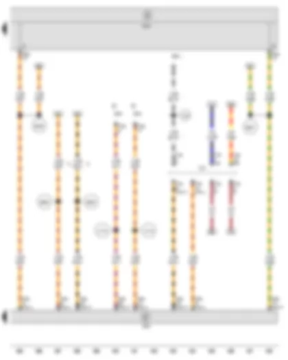
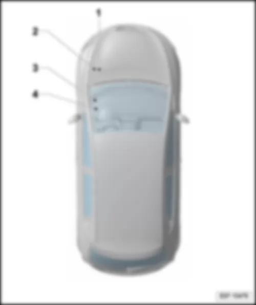
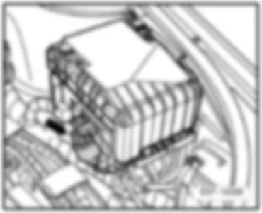
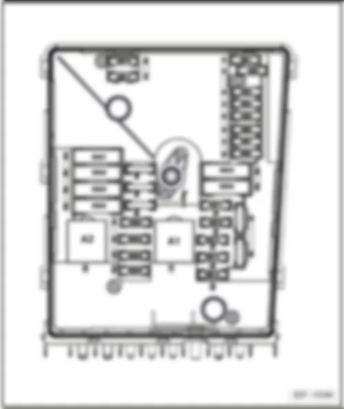
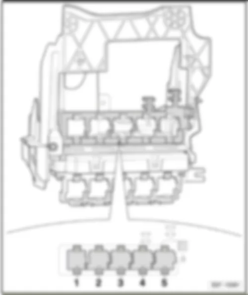
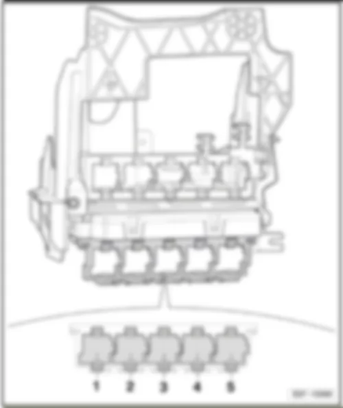
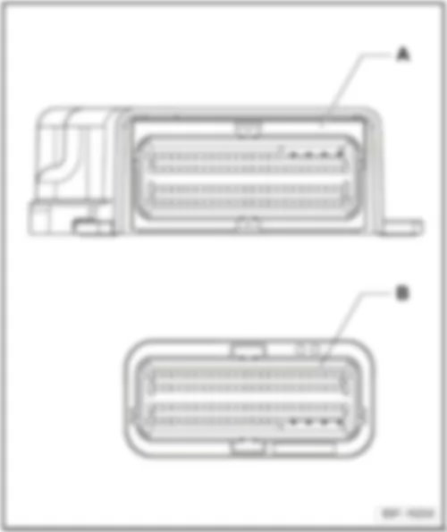
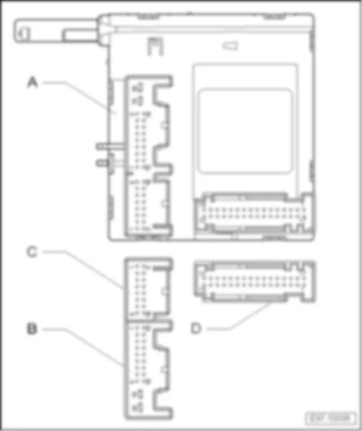
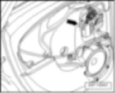
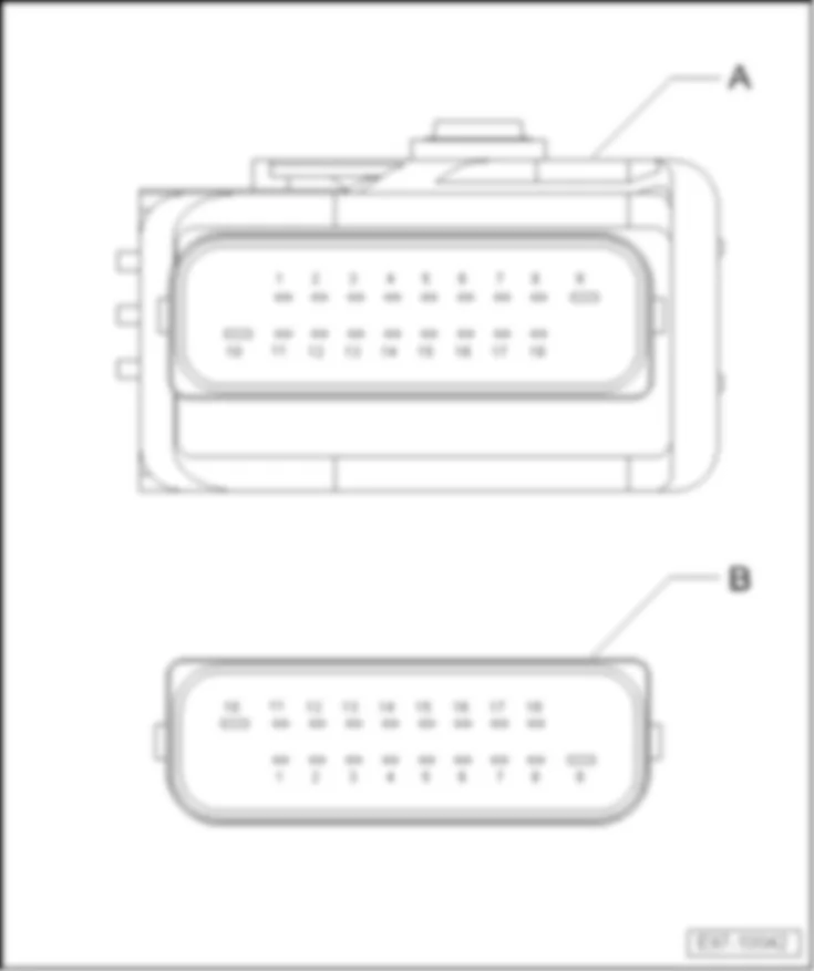
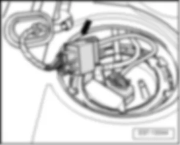
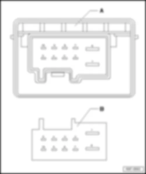
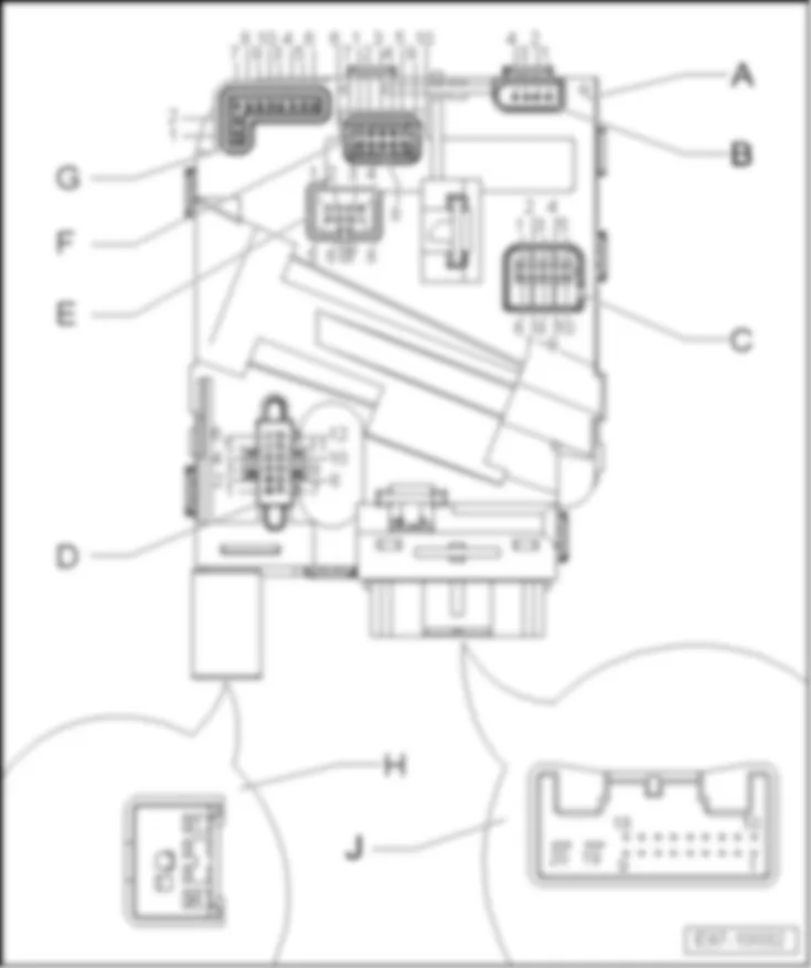
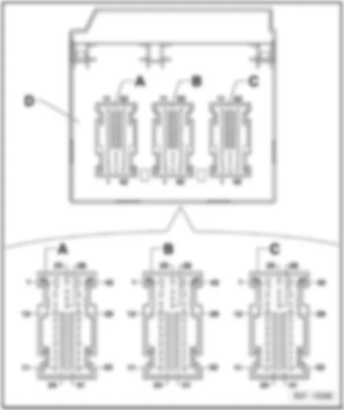
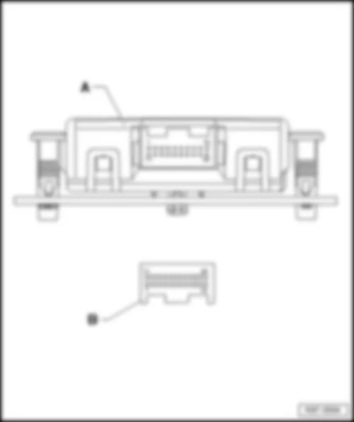
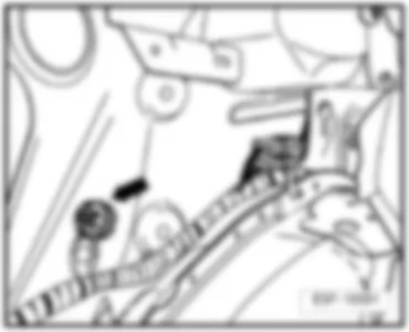
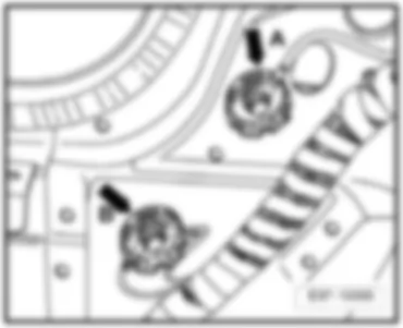
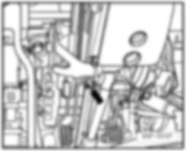
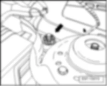
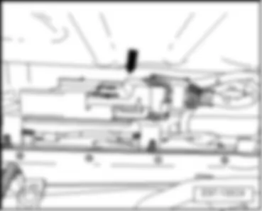
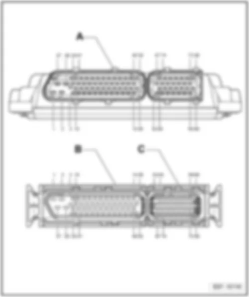
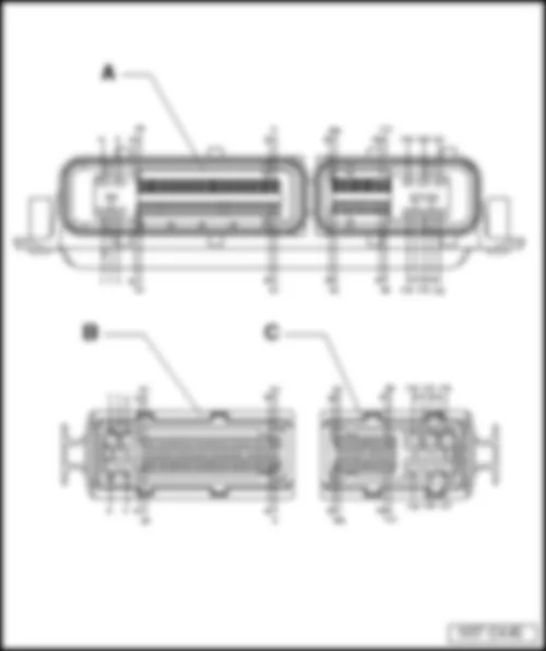
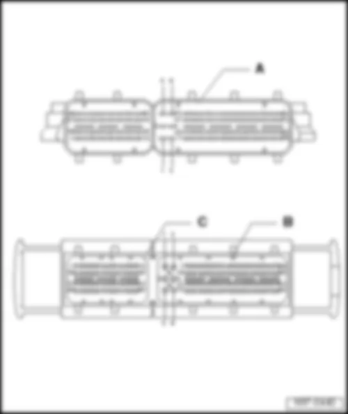
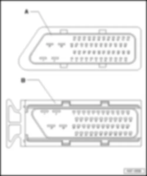
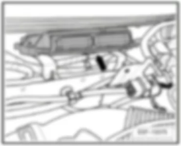
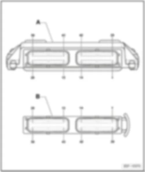
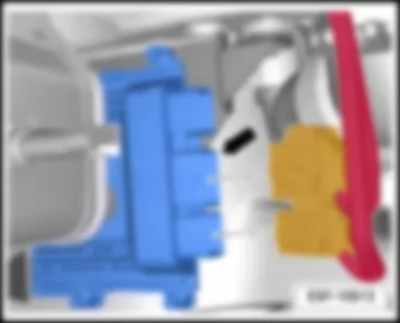
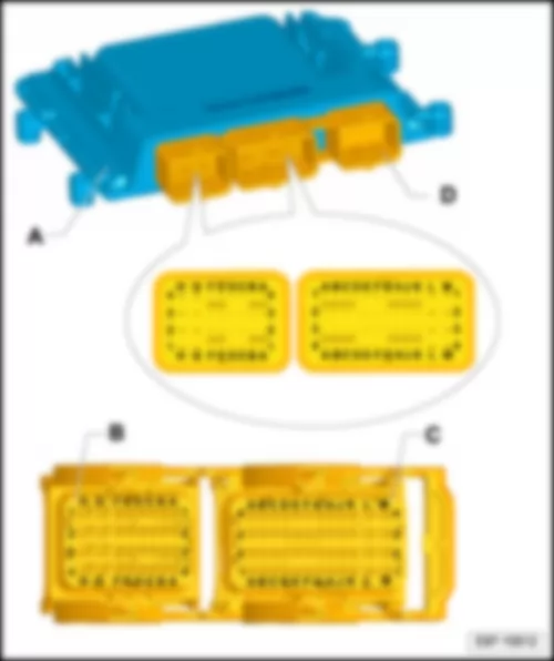
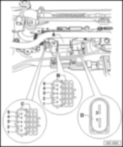
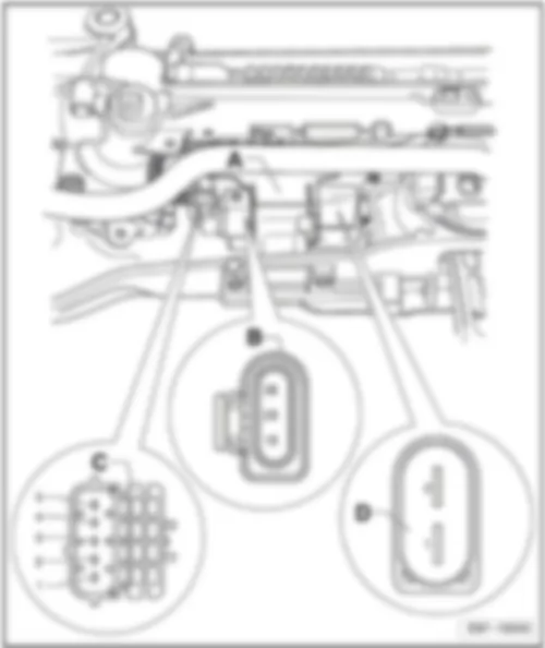
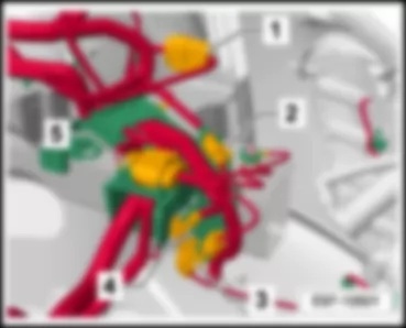
| Connector | Pin | Terminal | Equipment
H | Equipment
M | Equipment
B |
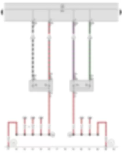
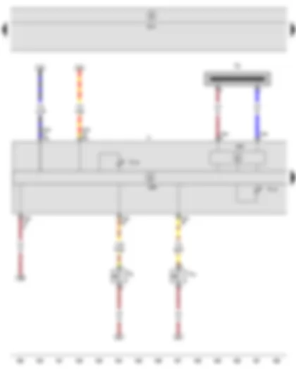
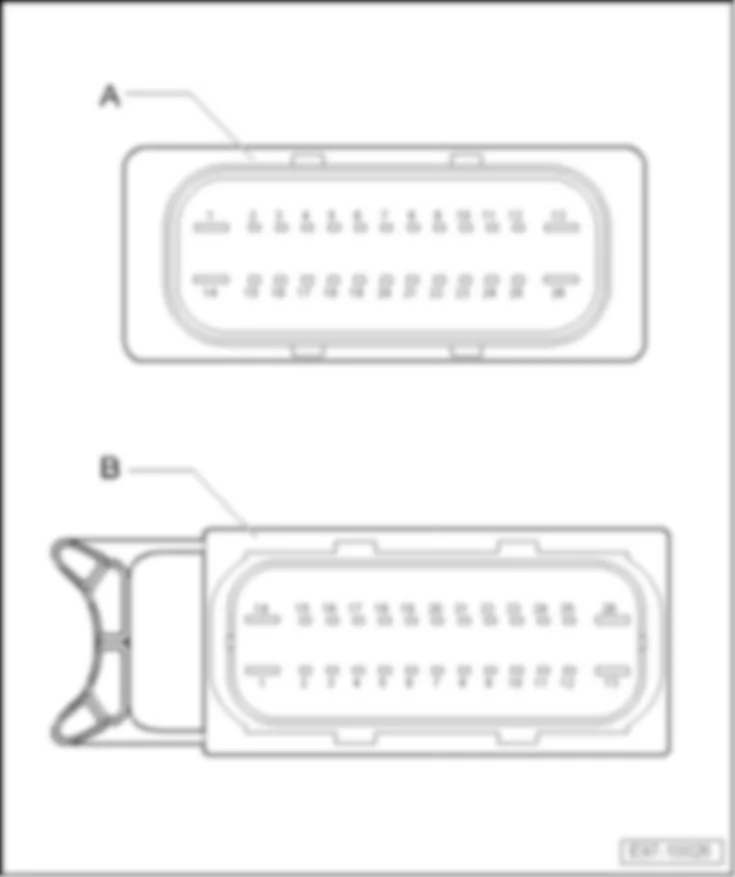
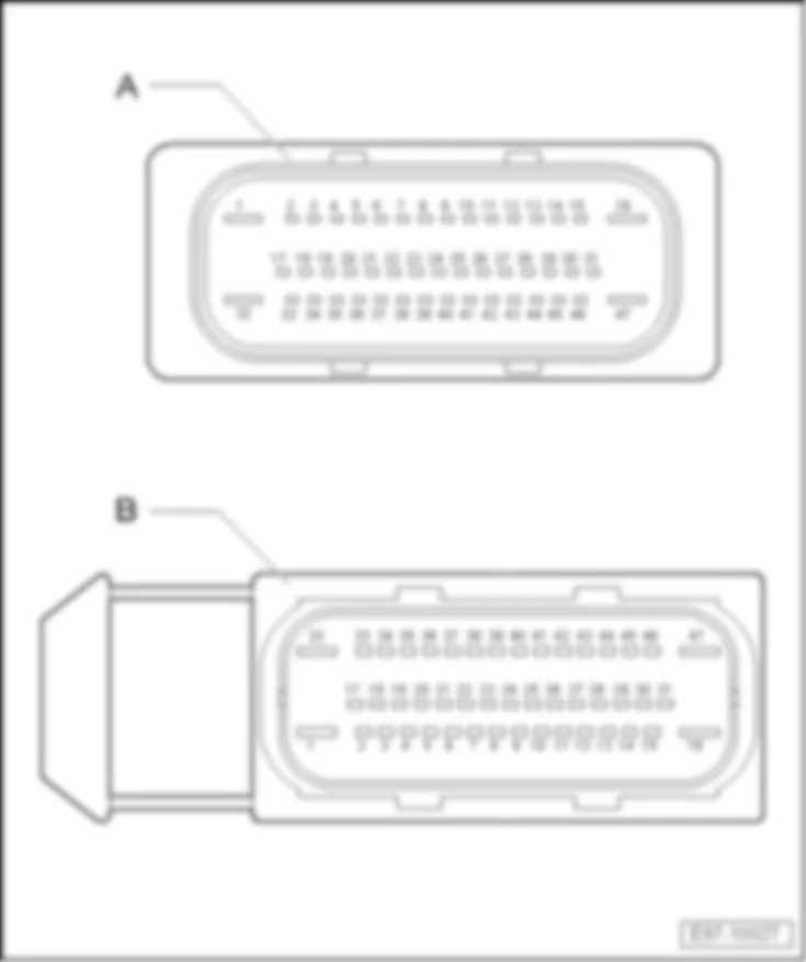
| A | 1 | Supply input (30A), left headlight bulbs | x | x | x |
| A | 2 | | | | |
| A | 3 | Right side repeater turn signal bulb signal output | x | x | x |
| A | 4 | Left side repeater turn signal bulb signal output | x | x | x |
| A | 5 | Left main beam bulb signal output | x | x | x |
| A | 6 | Right day driving light bulb signal output | x | x | x |
| A | 7 | | | | |
| A | 8 | | | | |
| A | 9 | Signal output for rear right turn signal bulb | x | x | x |
| A | 10 | Signal output for front left turn signal bulb | x | x | x |
| A | 11 | Left dipped beam bulb signal output | x | x | x |
| A | 12 | Rear lid remote release input signal | x | x | x |
| A | 13 | Rear lid handle release button input signal | x | x | x |
| A | 14 | Bonnet contact switch input signal | x | x | x |
| A | 15 | | | | |
| A | 16 | Reversing light switch signal input | x | x | x |
| A | 17 | Side light, rear fog light switch signal input | x | x | x |
| A | 18 | Light switch position "0" signal input | x | x | x |
| A | 19 | Input signal light switch, side light | x | x | x |
| A | 20 | Side light, automatic lights switch signal input | x | x | x |
| A | 21 | Side light, fog light switch signal input | x | x | - |
| A | 22 | Input signal light switch, dipped beam | x | x | x |
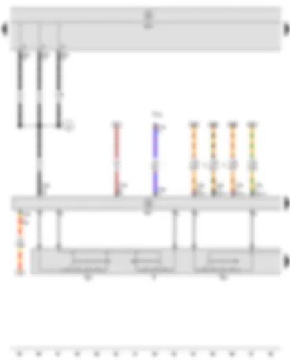
| A | 23 | Input for earth - reference voltage (31) | x | x | x |
| A | 24 | Input for reference voltage (30) | x | x | x |
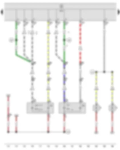
| A | 25 | Left fog light bulb signal output | x | x | - |
| A | 26 | Right brake light and side light bulb signal output | x | x | x |
| A | 27 | Left side light bulb in tail light signal output | x | x | x |
| A | 28 | Left reversing light bulb signal output (according to model) | x | x | x |
| | | Left day driving light bulb signal output (according to model) | | | |
| A | 29 | Rear lid remote release input signal | x | x | x |
| A | 30 | Rear right door contact switch input signal | x | x | x |
| A | 31 | | | | |
| A | 32 | | | | |
| A | 33 | | | | |
| A | 34 | | | | |
| A | 35 | Heated rear window button input signal | x | x | x |
| A | 36 | Interior monitoring deactivation input signal | x | x | x |
| A | 37 | | | | |
| A | 38 | Left central locking lock unit input signal (Safe) | x | x | x |
| A | 39 | | | | |
| A | 40 | Right central locking lock unit input signal (Safe) | x | x | x |
| A | 41 | Rear left door contact switch input signal | x | x | x |
| A | 42 | Input for earth - central locking (31) | x | x | x |
| A | 43 | Washer pump motor and rear window wiper motor signal output | x | x | x |
| A | 44 | Front right side light bulb signal output | x | x | x |
| A | 45 | High-level brake light bulb signal output | x | x | x |
| A | 46 | Tank filler flap locking motor signal output (+) | x | x | x |
| A | 47 | | | | |
| A | 48 | Central locking motor signal output in rear left door (-) | x | x | x |
| A | 49 | Central locking motor signal output in rear right door (+) | x | x | x |
| A | 50 | | | | |
| A | 51 | | | | |
| A | 52 | | | | |
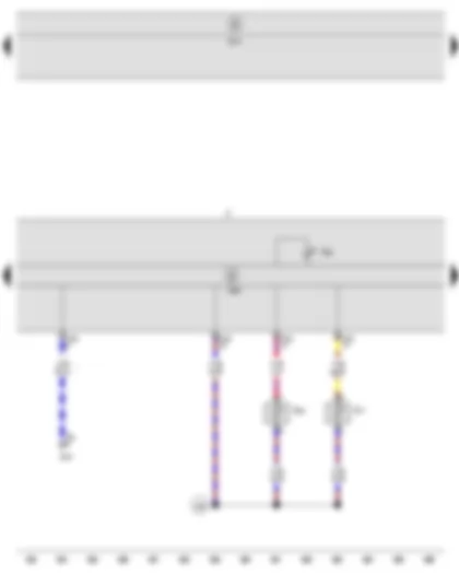
| B | 1 | Supply input (30), central locking | x | x | x |
| B | 2 | Washer pump motor and rear window wiper motor signal output | x | x | x |
| B | 3 | | | | |
| B | 4 | | | | |
| B | 5 | Tank filler flap locking motor signal output (-) | x | x | x |
| B | 6 | | | | |
| B | 7 | Central locking motor signal output in rear left door (+) | x | x | x |
| B | 8 | Central locking motor signal output in rear right door (-) | x | x | x |
| B | 9 | | | | |
| B | 10 | | | | |
| B | 11 | Rear lid release motor signal output (+) | x | x | x |
| B | 12 | Relay 15 signal output | x | x | x |
| B | 13 | | | | |
| B | 14 | Heated rear window warning lamp signal output | x | x | x |
| B | 15 | Illumination regulators - switches and instruments signal output (58d) | x | x | x |
| B | 16 | Sliding sunroof adjustment control unit signal output | x | x | x |
| B | 17 | Central locking deadlock function warning lamp -SAFE- signal output | x | x | x |
| B | 18 | Convenience locking signal output | x | x | x |
| B | 19 | | | | |
| B | 20 | | | | |
| B | 21 | Heated front seats control unit signal output | x | x | x |
| B | 22 | Heated rear window relay signal output | x | x | x |
| B | 23 | | | | |
| B | 24 | Hazard warning light system warning lamp signal output | x | x | x |
| B | 25 | | | | |
| B | 26 | Central locking motor signal output (Safe) in rear left door (+) | x | x | x |
| B | 27 | Central locking motor signal output (Safe) in rear right door (+) | x | x | x |
| B | 28 | Relay X signal output | x | x | x |
| B | 29 | Relay 50 signal output | x | x | x |
| B | 30 | Switches and instruments illumination regulator signal earth input | x | x | x |
| B | 31 | | | | |
| B | 32 | | | | |
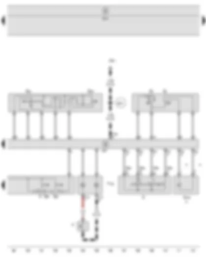
| B | 33 | LIN bus 1 (rain and light detector sensor) | x | x | x |
| B | 34 | | | | |
| B | 35 | | | | |
| B | 36 | LIN bus 2 (alarm) | x | x | x |
| B | 37 | Signal output for interior monitoring off warning lamp | x | x | x |
| B | 38 | Fuel pump control unit signal output | x | x | x |
| B | 39 | | | | |
| B | 40 | Headlight washer system relay signal output | x | x | x |
| B | 41 | Horn signal output | x | x | x |
| B | 42 | Supply input (30) ignition | x | x | x |
| B | 43 | Interior light (30G) supply output signal | x | x | x |
| B | 44 | | | | |
| B | 45 | | | | |
| B | 46 | | | | |
| B | 47 | | | | |
| B | 48 | | | | |
| B | 49 | | | | |
| B | 50 | | | | |
| B | 51 | Light switch input signal (58d) | x | x | x |
| B | 52 | Input for earth (31), left lights | x | x | x |
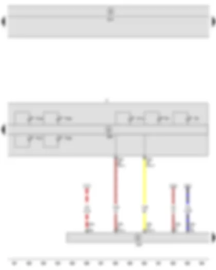
| C | 1 | Supply input (30a) alarm (models with alarm system only) | x | x | x |
| C | 2 | | | | |
| C | 3 | Right side light in tail light signal output | x | x | x |
| C | 4 | Left brake light and side light bulb signal output | x | x | x |
| C | 5 | Input for earth (31), right lights | x | x | x |
| C | 6 | | | | |
| C | 7 | Hazard warning light system switch input signal | x | x | x |
| C | 8 | | | | |
| C | 9 | | | | |
| C | 10 | Interior light signal output | x | x | x |
| C | 11 | | | | |
| C | 12 | | | | |
| C | 13 | Ignition/starter switch input signal (S) | x | x | x |
| C | 14 | Ignition/starter switch input signal (50) (without start/stop system) | x | x | x |
| | | Ignition/starter switch input signal (15) (with start/stop system) | | | |
| C | 15 | CAN-high, convenience | x | x | x |
| C | 16 | CAN-low, convenience | x | x | x |
| C | 17 | Brake pedal position sender signal input | x | x | x |
| C | 18 | | | | |
| C | 19 | | | | |
| C | 20 | | | | |
| C | 21 | | | | |
| C | 22 | | | | |
| C | 23 | | | | |
| C | 24 | | | | |
| C | 25 | Right fog light bulb signal output | x | x | - |
| C | 26 | Front left side light bulb signal output | x | x | x |
| C | 27 | Number plate light signal output | x | x | x |
| C | 28 | Right reversing light bulb signal output | x | x | x |
| C | 29 | | | | |
| C | 30 | P/N input signal (models with automatic gearbox) | x | x | x |
| | | Input for earth (31) (models with manual gearbox) | | | |
| C | 31 | Ignition/starter switch input signal (15) | x | x | x |
| C | 32 | Signal L alternator | x | x | x |
| C | 33 | | | | |
| C | 34 | Signal input (50) diagnosis (only models with stop/start system) | x | x | x |
| C | 35 | Illumination regulators - switches and instruments input signal (58d) | x | x | x |
| C | 36 | | | | |
| C | 37 | | | | |
| C | 38 | | | | |
| C | 39 | | | | |
| C | 40 | Central locking aerial input (GND), up to October 2009 | x | x | x |
| C | 41 | Central locking aerial signal input, up to October 2009 | x | x | x |
| C | 42 | Supply input (30), right headlight | x | x | x |
| C | 43 | | | | |
| C | 44 | | | | |
| C | 45 | | | | |
| C | 46 | Right main beam bulb signal output | x | x | x |
| C | 47 | Fog light bulb signal output (according to model) | x | x | x |
| C | 47 | Left day driving light bulb signal output (according to model) | x | x | x |
| C | 48 | Left Xenon screen motor signal output | x | | |
| C | 49 | Right Xenon screen motor signal output | x | | |
| C | 50 | Signal output for front right turn signal bulb | x | x | x |
| C | 51 | Signal output for rear left turn signal bulb | x | x | x |
| C | 52 | Right dipped beam bulb signal output | x | x | x |
| No. | T40a | Current Flow Diagram designation | Nominal value | | Function/component | Terminal |
| F1 | 32 | Fuse 1 on fuse holder B -SB1- | 30 A | - | Front passenger side wiper motor control unit -J584- | 30a |
| F2 | 39 | Fuse 2 on fuse holder B -SB2- | 30 A | - | Mechatronic unit for dual clutch gearbox -J743- (CDAA) | 30a |
| F3 | 38 | Fuse 3 on fuse holder B -SB3- | 5 A | - | Onboard supply control unit -J519- (via A/24), reference voltage | 30a |
| F4 | 27 | Fuse 4 on fuse holder B -SB4- | 20 A | - | ABS control unit -J104- | 30a |
| F5 | 40 | Fuse 5 on fuse holder B -SB5- | 15 A | - | Mechatronic unit for dual clutch gearbox -J743- DSG (AZV, BKD, BLS, BMM, BWA and CDAA) | 30a |
| F6 | 25 | Fuse 6 on fuse holder B -SB6- | 5 A | - | Control unit in dash panel insert -J285- | 30a |
| | | | | | Steering column electronics control unit -J527- | |
| F7 | 33 | Fuse 7 on fuse holder B -SB7- | 40 A | - | Terminal 15 voltage supply relay 2 -J681- | 30a |
| F8 | 34 | Fuse 8 on fuse holder B -SB8- | 15 A | - | Control unit with display for radio and navigation system -J503- | 30a |
| | | | | | Radio -R- | |
| F9 | 30 | Fuse 9 on fuse holder B -SB9- | 5 A | - | Telephone transmitter and receiver unit -R36- | 30a |
| F10 | 28 | Fuse 10 on fuse holder B -SB10- | 5 A | - | Main relay -J271- (BVY, BVZ and CAXC) | 30a |
| | | | | | Terminal 30 voltage supply relay -J317- (AZV, BKD, BLS, BMM, BMN, BXE, BXF and CEGA) | |
| | | | | | Engine control unit -J623- (BVY, BVZ, CAXC and CEGA) | |
| | | | 10 A | - | Main relay -J271- (BWA, BWJ and CDAA) | |
| | | | | | Terminal 30 voltage supply relay -J317- (BXW) | |
| | | | | | Engine control unit -J623- (BWA, BWJ, BXW and CDAA) | |
| F11 | 20 | Fuse 11 on fuse holder B -SB11- | - | - | vacant | |
| F12 | 24 | Fuse 12 on fuse holder B -SB12- | 5 A | - | Data bus diagnostic interface -J533- | 30a |
| F13 | 22 | Fuse 13 on fuse holder B -SB13- | 15 A | - | Engine control unit -J623- (BSE, BSF, BVY, BVZ, BWA, BWJ, BXW, CAXC, CCSA and CDAA) | 87a |
| | | | 30 A | - | Engine control unit -J623- (AZV, BKD, BLS, BMM, BMN, BXE, BXF and CEGA) | |
| F14 | 19 | Fuse 14 on fuse holder B -SB14- | 20 A | - | Ignition coil 1 with output stage -N70- (BVY, BVZ, BWA, BWJ, BXW, CAXC and CDAA) | 87a |
| | | | | | Ignition coil 2 with output stage -N127- (BVY, BVZ, BWA, BWJ, BXW, CAXC and CDAA) | |
| | | | | | Ignition transformer -N152- (BSE, BSF and CCSA) | |
| | | | | | Fuel pressure regulating valve -N276- (CEGA) | |
| | | | | | Fuel metering valve -N290- (CEGA) | |
| | | | | | Ignition coil 3 with output stage -N291- (BVY, BVZ, BWA, BWJ, BXW, CAXC and CDAA) | |
| | | | | | Ignition coil 4 with output stage -N292- (BVY, BVZ, BWA, BWJ, BXW, CAXC and CDAA) | |
| F15 | 26 | Fuse 15 on fuse holder B -SB15- | 5 A | - | Fuel pump relay -J17- (AZV, BKD, BLS, BMM, BMN, BXE, BXF and CEGA) | 87a |
| | | | | | Electric fuel pump 2 relay -J49- (CEGA) | |
| | | | | | Automatic glow period control unit -J179- (AZV, BKD, BLS, BMM, BMN, BXE, BXF and CEGA) | |
| | | | | | Low heat output relay -J359- | |
| | | | | | High heat output relay -J360- | |
| | | | 10 A | - | Injector, cylinder 1 -N30- (BXW) | |
| | | | | | Injector, cylinder 2 -N31- (BXW) | |
| | | | | | Injector, cylinder 3 -N32- (BXW) | |
| | | | | | Injector, cylinder 4 -N33- (BXW) | |
| | | | | | Circulation pump relay -J160- (BWA and BWJ) | |
| | | | | | Lambda probe heater -Z19- (CAXC) | |
| | | | | | Lambda probe 1 heater after catalytic converter -Z29- (BVY, BVZ and CAXC) | |
| | | | | | Lambda probe 2 heater after catalytic converter -Z30- (BVY) | |
| | | | | | Lambda probe 3 heater after catalytic converter -Z64- (BVY) | |
| F16 | 23 | Fuse 16 on fuse holder B -SB16- | 30 A | - | Onboard supply control unit -J519- (via C/42), right headlight bulb supply | 30a |
| F17 | 18 | Fuse 17 on fuse holder B -SB17- | 15 A | - | Dual tone horn relay -J4- | 30a |
| F18 | 17 | Fuse 18 on fuse holder B -SB18- | - | - | vacant | |
| F19 | 12 | Fuse 19 on fuse holder B -SB19- | 30 A | - | Wiper motor control unit -J400- , driver side | 30a |
| F20 | 13 | Fuse 20 on fuse holder B -SB20- | 10 A | - | Coolant circulation pump -V50- (CAXC) | 87a |
| | | | 20 A | - | Fuel pressure regulating valve -N276- (CDAA) | |
| F21 | 16 | Fuse 21 on fuse holder B -SB21- | 10 A | - | Lambda probe heater -Z19- (BLS, BMM, BMN and CEGA) | 87a |
| | | | 15 A | - | Lambda probe heater -Z19- (BSE, BSF, BVY, BVZ, BXW, CCSA and CDAA) | |
| | | | | | Lambda probe 1 heater after catalytic converter -Z29- (BSE, BSF, BXW, CCSA and CDAA) | |
| F22 | 14 | Fuse 22 on fuse holder B -SB22- | 5 A | - | Clutch position sender -G476- | 87a |
| F23 | 21 | Fuse 23 on fuse holder B -SB23- | 5 A | - | Continued coolant circulation relay -J151- (CDAA) | 87a |
| | | | | | Circulation pump relay -J160- (BWA and BWJ) | |
| | | | | | Secondary air pump relay -J299- (BSE and CCSA) | |
| | | | | | Motronic current supply relay -2- -J670- (BWA, BWJ) | |
| | | | 10 A | - | Exhaust gas recirculation valve -N18- (AZV, BKD, BXE and BXF) | |
| | | | | | Charge pressure control solenoid valve -N75- (AZV, BKD, BLS, BMM, BMN, BXE, BXF and CEGA) | |
| | | | | | Intake manifold flap valve -N316- (BMN) | |
| | | | | | Exhaust gas recirculation cooler change-over valve -N345- (AZV, BKD, BLS, BMM, BMN, BXE, BXF and CEGA) | |
| | | | 15 A | - | Fuel pressure regulating valve -N276- (BVY, BVZ and CAXC) | |
| F24 | 11 | Fuse 24 on fuse holder B -SB24- | 10 A | - | Radiator fan control unit C1781 -J293- | 87a |
| | | | | | Additional coolant pump relay -J496- (CAXC) | |
| | | | | | Engine component current supply relay -J757- (CDAA) | |
| | | | | | Charge pressure control solenoid valve -N75- (CAXC and CDAA) | |
| | | | | | Activated charcoal filter system solenoid valve 1 -N80- (BSE, BSF, BVY, BVZ, BXW, CAXC, CCSA and CDAA) | |
| | | | | | Variable intake manifold change-over valve -N156- (BSE, BSF, BVY, BVZ and CCSA) | |
| | | | | | Inlet camshaft control valve 1 -N205- (BVY, BVZ, BWA, BWJ, CAXC and CDAA) | |
| | | | | | Turbocharger air recirculation valve -N249- (CAXC and CDAA) | |
| | | | | | Intake manifold flap valve -N316- (CDAA) | |
| | | | | | Oil pressure warning lamp -N428- (CDAA) | |
| | | | | | Radiator fan -V7- | |
| | | | | | Intake manifold flap motor -V157- (AZV, BKD, BXE and BXF) | |
| | | | | | Coolant circulation pump 2 -V178- (CEGA) | |
| F25 | 31 | Fuse 25 on fuse holder B -SB25- | 40 A | - | ABS control unit -J104- | 30a |
| F26 | 35 | Fuse 26 on fuse holder B -SB26- | 30 A | - | Onboard supply control unit -J519- (via A/1), left headlight bulb supply | 30a |
| F27 | 1 | Fuse 27 on fuse holder B -SB27- | 40 A | - | Secondary air pump motor -V101- (BSE and CCSA) | 87a |
| | | | 50 A | - | Automatic glow period control unit -J179- (AZV, BKD, BLS, BMM, BMN, BXE, BXF and CEGA) | 30a |
| F28 | 4 | Fuse 28 on fuse holder B -SB28- | - | - | vacant | |
| F29 | 2 | Fuse 29 on fuse holder B -SB29- | 50 A | - | Sliding sunroof adjustment control unit -J245- | 30a |
| | | | | | Onboard supply control unit -J519- (without Autolock function) (via B/1), supply central locking | |
| | | | | | Heated front seats control unit -J774- | |
| | | | | | Headlight washer system relay -J39- | |
| F30 | 3 | Fuse 30 on fuse holder B -SB30- | 50 A | - | X-contact relief relay -J59- | 30a |
| No. | | Current Flow Diagram designation | Nominal value | | Function/component | Terminal |
| F1 | 32 | Fuse 1 on fuse holder B -SB1- | 30 A | - | Front passenger side wiper motor control unit -J584- | 30a |
| F2 | 39 | Fuse 2 on fuse holder B -SB2- | 30 A | - | Mechatronic unit for dual clutch gearbox -J743- (BSF, CAYC and CDAA) | 30a |
| F3 | 38 | Fuse 3 on fuse holder B -SB3- | 5 A | - | Battery monitor control unit -J367- (CAYC with stop/start system) | 30a |
| | | | | | Onboard supply control unit -J519- (via A/24), reference voltage | |
| F4 | 27 | Fuse 4 on fuse holder B -SB4- | 20 A | - | ABS control unit -J104- | 30a |
| F5 | 40 | Fuse 5 on fuse holder B -SB5- | 15 A | - | Mechatronic unit for dual clutch gearbox -J743- (AZV, BKD, BLS, BMM, BSF, CAYC, CCZB, CDAA and CEGA) | 30a |
| F6 | 25 | Fuse 6 on fuse holder B -SB6- | 5 A | - | Control unit in dash panel insert -J285- (without stop/start system) | 30a |
| | | | | | Steering column electronics control unit -J527- | |
| F7 | 33 | Fuse 7 on fuse holder B -SB7- | 40 A | - | Terminal 15 voltage supply relay 2 -J681- | 30a |
| F8 | 34 | Fuse 8 on fuse holder B -SB8- | 15 A | - | Control unit with display for radio and navigation system -J503- | 30a |
| | | | | | Voltage stabiliser -J532- (CAYC with stop/start system) | |
| | | | | | Radio -R- | |
| F9 | 30 | Fuse 9 on fuse holder B -SB9- | 5 A | - | Telephone transmitter and receiver unit -R36- (without stop/start system) | 30a |
| F10 | 28 | Fuse 10 on fuse holder B -SB10- | 5 A | - | Main relay -J271- (CAXC) | 30a |
| | | | | | Terminal 30 voltage supply relay -J317- (AZV, BKD, BLS, BMM, BXE, BXF, CAYC and CEGA) | |
| | | | | | Engine control unit -J623- (CAXC, CAYC and CEGA) | |
| | | | 10 A | - | Main relay -J271- (CCZB, CDAA, CDLA and CDLD) | |
| | | | | | Terminal 30 voltage supply relay -J317- (BXW) | |
| | | | | | Engine control unit -J623- (BXW, CCZB, CDAA, CDLA and CDLD) | |
| F11 | 20 | Fuse 11 on fuse holder B -SB11- | - | - | vacant | |
| F12 | 24 | Fuse 12 on fuse holder B -SB12- | 5 A | - | Data bus diagnostic interface -J533- | 30a |
| F13 | 22 | Fuse 13 on fuse holder B -SB13- | 15 A | - | Engine control unit -J623- (BSE, BSF, BXW, CAXC, CCSA, CCZB, CDAA and CHGA) | 87a |
| | | | 30 A | - | Engine control unit -J623- (AZV, BKD, BLS, BMM, BXE, BXF, CAYC and CEGA) | |
| F14 | 19 | Fuse 14 on fuse holder B -SB14- | 20 A | - | Ignition coil 1 with output stage -N70- (BXW, CAXC, CCZB, CDAA, CDLA and CDLD) | 87a |
| | | | | | Ignition coil 2 with output stage -N127- (BXW, CAXC, CCZB, CDAA, CDLA and CDLD) | |
| | | | | | Ignition transformer -N152- (BSE, BSF, CCSA and CHGA) | |
| | | | | | Fuel pressure regulating valve -N276- (CAYC and CEGA) | |
| | | | | | Fuel metering valve -N290- (CAYC and CEGA) | |
| | | | | | Ignition coil 3 with output stage -N291- (BXW, CAXC, CCZB, CDAA, CDLA and CDLD) | |
| | | | | | Ignition coil 4 with output stage -N292- (BXW, CAXC, CCZB, CDAA, CDLA and CDLD) | |
| F15 | 26 | Fuse 15 on fuse holder B -SB15- | 5 A | - | Fuel pump relay -J17- (AZV, BKD, BLS, BMM, BXE, BXF, CAYC and CEGA) | 87a |
| | | | | | Electric fuel pump 2 relay -J49- (CEGA) | |
| | | | | | Automatic glow period control unit -J179- (AZV, BKD, BLS, BMM, BXE, BXF, CAYC and CEGA) | |
| | | | | | Low heat output relay -J359- | |
| | | | | | High heat output relay -J360- | |
| | | | 10 A | - | Injector, cylinder 1 -N30- (BXW) | |
| | | | | | Injector, cylinder 2 -N31- (BXW) | |
| | | | | | Injector, cylinder 3 -N32- (BXW) | |
| | | | | | Injector, cylinder 4 -N33- (BXW) | |
| | | | | | Continued coolant circulation relay -J151- (CDLA and CDLD) | |
| | | | | | Lambda probe heater -Z19- (CAXC) | |
| | | | | | Lambda probe 1 heater after catalytic converter -Z29- (CAXC) | |
| F16 | 23 | Fuse 16 on fuse holder B -SB16- | 30 A | - | Onboard supply control unit -J519- (via C/42), right headlight bulb supply | 30a |
| F17 | 18 | Fuse 17 on fuse holder B -SB17- | 15 A | - | Dual tone horn relay -J4- | 30a |
| F18 | 17 | Fuse 18 on fuse holder B -SB18- | - | - | vacant | |
| F19 | 12 | Fuse 19 on fuse holder B -SB19- | 30 A | - | Wiper motor control unit -J400- , driver side | 30a |
| F20 | 13 | Fuse 20 on fuse holder B -SB20- | 10 A | - | Coolant circulation pump -V50- (CAXC) | 87a |
| | | | 20 A | - | Fuel pressure regulating valve -N276- (CCZB and CDAA) | |
| F21 | 16 | Fuse 21 on fuse holder B -SB21- | 10 A | - | Lambda probe heater -Z19- (BLS, BMM, BMN and CEGA) | 87a |
| | | | 15 A | - | Lambda probe heater -Z19- (BSE, BSF, BXW, CCSA, CCZB, CDAA and CHGA) | |
| | | | | | Lambda probe 1 heater after catalytic converter -Z29- (BSE, BSF, BXW, CCSA, CCZB, CDAA and CHGA) | |
| F22 | 14 | Fuse 22 on fuse holder B -SB22- | 5 A | - | Clutch position sender -G476- | 87a |
| F23 | 21 | Fuse 23 on fuse holder B -SB23- | 5 A | - | Continued coolant circulation relay -J151- (CCZB, CDAA, CDLA and CDLD) | 87a |
| | | | | | Secondary air pump relay -J299- (BSE, CCSA and CHGA) | |
| | | | | | Motronic current supply relay -2- -J670- (CDLA and CDLD) | |
| | | | 10 A | - | Intake manifold preheating relay -J81- (CAYC) | |
| | | | | | Exhaust gas recirculation valve -N18- (AZV, BKD, BXE and BXF) | |
| | | | | | Charge pressure control solenoid valve -N75- (AZV, BKD, BLS, BMM, BXE, BXF, CAYC and CEGA) | |
| | | | | | Exhaust gas recirculation cooler change-over valve -N345- (AZV, BKD, BLS, BMM, BXE, BXF, CAYC and CEGA) | |
| | | | 15 A | - | Fuel pressure regulating valve -N276- (CAXC) | |
| F24 | 11 | Fuse 24 on fuse holder B -SB24- | 10 A | - | Radiator fan control unit C1781 -J293- | 87a |
| | | | | | Additional coolant pump relay -J496- (CAXC) | |
| | | | | | Engine component current supply relay -J757- (CCZB and CDAA) | |
| | | | | | Charge pressure control solenoid valve -N75- (CAXC, CCZB and CDAA) | |
| | | | | | Activated charcoal filter system solenoid valve 1 -N80- (BSE, BSF, BXW, CAXC, CCSA, CCZB, CDAA and CHGA) | |
| | | | | | Variable intake manifold change-over valve -N156- (BSE, BSF, CCSA and CHGA) | |
| | | | | | Inlet camshaft control valve 1 -N205- (CAXC, CCZB, CDAA, CDLA and CDLD) | |
| | | | | | Turbocharger air recirculation valve -N249- (CAXC, CCZB and CDAA) | |
| | | | | | Intake manifold flap valve -N316- (CCZB and CDAA) | |
| | | | | | Oil pressure warning lamp -N428- (CCZB and CDAA) | |
| | | | | | Radiator fan -V7- | |
| | | | | | Intake manifold flap motor -V157- (AZV, BKD, BXE and BXF) | |
| | | | | | Coolant circulation pump 2 -V178- (CAYC and CEGA) | |
| F25 | 31 | Fuse 25 on fuse holder B -SB25- | 40 A | - | ABS control unit -J104- | 30a |
| F26 | 35 | Fuse 26 on fuse holder B -SB26- | 30 A | - | Onboard supply control unit -J519- (via A/1), left headlight bulb supply | 30a |
| F27 | 1 | Fuse 27 on fuse holder B -SB27- | 40 A | - | Secondary air pump motor -V101- (BSE, CCSA and CHGA) | 87a |
| | | | 50 A | - | Automatic glow period control unit -J179- (AZV, BKD, BLS, BMM, BXE, BXF, CAYC and CEGA) | 30a |
| F28 | 4 | Fuse 28 on fuse holder B -SB28- | - | - | vacant | |
| F29 | 2 | Fuse 29 on fuse holder B -SB29- | 50 A | - | Sliding sunroof adjustment control unit -J245- | 30a |
| | | | | | Onboard supply control unit -J519- (without Autolock function) (via B/1), supply central locking | |
| | | | | | Heated front seats control unit -J774- | |
| | | | | | Headlight washer system relay -J39- | |
| F30 | 3 | Fuse 30 on fuse holder B -SB30- | 50 A | - | X-contact relief relay -J59- | 30a |
| No. | T40a | Current Flow Diagram designation | Nominal value | | Function/component | Terminal |
| F1 | 32 | Fuse 1 on fuse holder B -SB1- | 30 A | - | Front passenger side wiper motor control unit -J584- | 30a |
| F2 | 39 | Fuse 2 on fuse holder B -SB2- | 30 A | - | Mechatronic unit for dual clutch gearbox -J743- (BSF, CAYB, CAYC and CDAA) | 30a |
| F3 | 38 | Fuse 3 on fuse holder B -SB3- | 5 A | - | Battery monitor control unit -J367- (CAYB, CAYC and CBZB with stop/start system) | 30a |
| | | | | | Onboard supply control unit -J519- (via A/24), reference voltage | |
| F4 | 27 | Fuse 4 on fuse holder B -SB4- | 20 A | - | ABS control unit -J104- | 30a |
| F5 | 40 | Fuse 5 on fuse holder B -SB5- | 15 A | - | Mechatronic unit for dual clutch gearbox -J743- (AZV, BKD, BLS, BMM, BSF, CAYB, CAYC, CCZB, CDAA, CEGA and CFHC) | 30a |
| F6 | 25 | Fuse 6 on fuse holder B -SB6- | 5 A | - | Control unit in dash panel insert -J285- (without stop/start system) | 30a |
| | | | | | Steering column electronics control unit -J527- | |
| F7 | 33 | Fuse 7 on fuse holder B -SB7- | 40 A | - | Terminal 15 voltage supply relay 2 -J681- | 30a |
| F8 | 34 | Fuse 8 on fuse holder B -SB8- | 15 A | - | Control unit with display for radio and navigation system -J503- | 30a |
| | | | | | Voltage stabiliser -J532- (CAYB, CAYC and CBZB with stop/start system) | |
| | | | | | Radio -R- | |
| F9 | 30 | Fuse 9 on fuse holder B -SB9- | 5 A | - | Telephone transmitter and receiver unit -R36- (without stop/start system) | 30a |
| F10 | 28 | Fuse 10 on fuse holder B -SB10- | 5 A | - | Main relay -J271- (CAXC and CBZB) | 30a |
| | | | | | Terminal 30 voltage supply relay -J317- (AZV, BKD, BLS, BMM, BXE, BXF, CAYB, CAYC, CEGA, CFHC and CFJA) | |
| | | | | | Engine control unit -J623- (CAXC, CAYB, CAYC, CBZB, CEGA, CFHC and CFJA) | |
| | | | 10 A | - | Main relay -J271- (CCZB, CDAA, CDLA and CDLD) | |
| | | | | | Terminal 30 voltage supply relay -J317- (CGGB) | |
| | | | | | Engine control unit -J623- (CCZB, CDAA, CDLA, CDLD and CGGB) | |
| F11 | 20 | Fuse 11 on fuse holder B -SB11- | - | - | vacant | |
| F12 | 24 | Fuse 12 on fuse holder B -SB12- | 5 A | - | Data bus diagnostic interface -J533- | 30a |
| F13 | 22 | Fuse 13 on fuse holder B -SB13- | 15 A | - | Engine control unit -J623- (BSE, BSF, CAXC, CBZB, CCSA, CCZB, CDAA, CDLA, CDLD, CGGB, CHGA and CMXA) | 87a |
| | | | 30 A | - | Engine control unit -J623- (AZV, BKD, BLS, BMM, BXE, BXF, CAYB, CAYC, CEGA, CFHC and CFJA) | |
| F14 | 19 | Fuse 14 on fuse holder B -SB14- | 20 A | - | Ignition coil 1 with output stage -N70- (CAXC, CCZB, CDAA, CDLA, CDLD and CGGB) | 87a |
| | | | | | Ignition coil 2 with output stage -N127- (CAXC, CCZB, CDAA, CDLA, CDLD and CGGB) | |
| | | | | | Ignition transformer -N152- (BSE, BSF, CCSA, CHGA, CBZB and CMXA) | |
| | | | | | Fuel pressure regulating valve -N276- (CAYB, CAYC, CEGA, CFHC and CFJA) | |
| | | | | | Fuel metering valve -N290- (CAYB, CAYC, CEGA, CFHC and CFJA) | |
| | | | | | Ignition coil 3 with output stage -N291- (CAXC, CCZB, CDAA, CDLA, CDLD and CGGB) | |
| | | | | | Ignition coil 4 with output stage -N292- (CAXC, CCZB, CDAA, CDLA, CDLD and CGGB) | |
| F15 | 26 | Fuse 15 on fuse holder B -SB15- | 5 A | - | Fuel pump relay -J17- (AZV, BKD, BLS, BMM, BXE, BXF, CAYB, CAYC, CEGA, CFHC and CFJA) | 87a |
| | | | | | Electric fuel pump 2 relay -J49- (CEGA, CFHC and CFJA) | |
| | | | | | Automatic glow period control unit -J179- (AZV, BKD, BLS, BMM, BXE, BXF, CAYB, CAYC, CEGA, CFHC and CFJA) | |
| | | | | | Low heat output relay -J359- | |
| | | | | | High heat output relay -J360- | |
| | | | 10 A | - | Injector, cylinder 1 -N30- (CGGB) | |
| | | | | | Injector, cylinder 2 -N31- (CGGB) | |
| | | | | | Injector, cylinder 3 -N32- (CGGB) | |
| | | | | | Injector, cylinder 4 -N33- (CGGB) | |
| | | | | | Continued coolant circulation relay -J151- (CDLA and CDLD) | |
| | | | | | Lambda probe heater -Z19- (CAXC and CBZB) | |
| | | | | | Lambda probe 1 heater after catalytic converter -Z29- (CAXC and CBZB) | |
| | | | 15 A | - | Sender for gas gauge -G707- (CHGA) | |
| | | | | | Gas mode control unit -J659- (CHGA) | |
| | | | | | Gas injection valve 1 -N366- (CHGA) | |
| | | | | | Gas injection valve 2 -N367- (CHGA) | |
| | | | | | Gas injection valve 3 -N368- (CHGA) | |
| | | | | | Gas injection valve 4 -N369- (CHGA) | |
| | | | | | High pressure valve for gas mode -N372- (CHGA) | |
| | | | | | Gas reservoir valve -N495- (CHGA) | |
| F16 | 23 | Fuse 16 on fuse holder B -SB16- | 30 A | - | Onboard supply control unit -J519- (via C/42), right headlight bulb supply | 30a |
| F17 | 18 | Fuse 17 on fuse holder B -SB17- | 15 A | - | Dual tone horn relay -J4- | 30a |
| F18 | 17 | Fuse 18 on fuse holder B -SB18- | - | - | vacant | |
| F19 | 12 | Fuse 19 on fuse holder B -SB19- | 30 A | - | Wiper motor control unit -J400- , driver side | 30a |
| F20 | 13 | Fuse 20 on fuse holder B -SB20- | 10 A | - | Coolant circulation pump -V50- (CAXC and CBZB) | 87a |
| | | | 20 A | - | Fuel pressure regulating valve -N276- (CCZB and CDAA) | |
| F21 | 16 | Fuse 21 on fuse holder B -SB21- | 10 A | - | Lambda probe heater -Z19- (BLS, BMM, CAYB, CAYC, CEGA, CFHC and CFJA) | 87a |
| | | | 15 A | - | Lambda probe heater -Z19- (BSE, BSF, CCSA, CCZB, CDAA, CGGB, CHGA and CMXA) | |
| | | | | | Lambda probe 1 heater after catalytic converter -Z29- (BSE, BSF, CCSA, CCZB, CDAA, CGGB, CHGA and CMXA) | |
| F22 | 14 | Fuse 22 on fuse holder B -SB22- | 5 A | - | Clutch position sender -G476- | 87a |
| F23 | 21 | Fuse 23 on fuse holder B -SB23- | 5 A | - | Continued coolant circulation relay -J151- (CCZB, CDAA, CDLA and CDLD) | 87a |
| | | | | | Secondary air pump relay -J299- (BSE, CCSA, CHGA and CMXA) | |
| | | | | | Motronic current supply relay -2- -J670- (CDLA and CDLD) | |
| | | | 10 A | - | Air mass meter -G70- (CFHC and CFJA) | |
| | | | | | Intake manifold preheating relay -J81- (CAYB and CAYC) | |
| | | | | | Exhaust gas recirculation valve -N18- (AZV, BKD, BXE and BXF) | |
| | | | | | Charge pressure control solenoid valve -N75- (AZV, BKD, BLS, BMM, BXE, BXF, CAYB, CAYC, CEGA, CFHC and CFJA) | |
| | | | | | Exhaust gas recirculation cooler change-over valve -N345- (AZV, BKD, BLS, BMM, BXE, BXF, CAYB, CAYC, CEGA, CFHC and CFJA) | |
| | | | 15 A | - | Fuel pressure regulating valve -N276- (CAXC and CBZB) | |
| F24 | 11 | Fuse 24 on fuse holder B -SB24- | 10 A | - | Radiator fan control unit C1781 -J293- | 87a |
| | | | | | Additional coolant pump relay -J496- (CAXC and CBZB) | |
| | | | | | Engine component current supply relay -J757- (CCZB and CDAA) | |
| | | | | | Charge pressure control solenoid valve -N75- (CAXC, CCZB and CDAA) | |
| | | | | | Activated charcoal filter system solenoid valve 1 -N80- (BSE, BSF, CAXC, CBZB, CCSA, CCZB, CDAA, CGGB, CHGA and CMXA) | |
| | | | | | Variable intake manifold change-over valve -N156- (BSE, BSF, CCSA, CHGA and CMXA) | |
| | | | | | Inlet camshaft control valve 1 -N205- (CAXC, CCZB, CDAA, CDLA and CDLD) | |
| | | | | | Turbocharger air recirculation valve -N249- (CAXC, CCZB and CDAA) | |
| | | | | | Intake manifold flap valve -N316- (CCZB and CDAA) | |
| | | | | | Oil pressure warning lamp -N428- (CCZB and CDAA) | |
| | | | | | Refrigerant circulation solenoid valve -N492- (CBZB) | |
| | | | | | Radiator fan -V7- | |
| | | | | | Intake manifold flap motor -V157- (AZV, BKD, BXE and BXF) | |
| | | | | | Coolant circulation pump 2 -V178- (CAYB, CAYC, CEGA, CFHC and CFJA) | |
| F25 | 31 | Fuse 25 on fuse holder B -SB25- | 40 A | - | ABS control unit -J104- | 30a |
| F26 | 35 | Fuse 26 on fuse holder B -SB26- | 30 A | - | Onboard supply control unit -J519- (via A/1), left headlight bulb supply | 30a |
| F27 | 1 | Fuse 27 on fuse holder B -SB27- | 40 A | - | Secondary air pump motor -V101- (BSE, CCSA, CHGA and CMXA) | 87a |
| | | | 50 A | - | Automatic glow period control unit -J179- (AZV, BKD, BLS, BMM, BXE, BXF, CAYB, CAYC, CEGA, CFHC and CFJA) | 30a |
| F28 | 4 | Fuse 28 on fuse holder B -SB28- | - | - | vacant | |
| F29 | 2 | Fuse 29 on fuse holder B -SB29- | 50 A | - | Sliding sunroof adjustment control unit -J245- | 30a |
| | | | | | Onboard supply control unit -J519- (without Autolock function) (via B/1), supply central locking | |
| | | | | | Heated front seats control unit -J774- | |
| | | | | | Headlight washer system relay -J39- | |
| F30 | 3 | Fuse 30 on fuse holder B -SB30- | 50 A | - | X-contact relief relay -J59- | 30a |
| No. | T40a | Current Flow Diagram designation | Nominal value | | Function/component | Terminal |
| F1 | 32 | Fuse 1 on fuse holder B -SB1- | 30 A | - | Front passenger side wiper motor control unit -J584- | 30a |
| F2 | 39 | Fuse 2 on fuse holder B -SB2- | 30 A | - | Mechatronic unit for dual clutch gearbox -J743- (BSF, CAYB, CAYC and CDAA) | 30a |
| F3 | 38 | Fuse 3 on fuse holder B -SB3- | 5 A | - | Battery monitor control unit -J367- (CAYC and CBZB with stop/start system) | 30a |
| | | | | | Onboard supply control unit -J519- (via A/24), reference voltage | |
| F4 | 27 | Fuse 4 on fuse holder B -SB4- | 20 A | - | ABS control unit -J104- | 30a |
| F5 | 40 | Fuse 5 on fuse holder B -SB5- | 15 A | - | Mechatronic unit for dual clutch gearbox -J743- (BKD, BSF, CAYB, CAYC, CCZB, CDAA, CEGA and CFHC) | 30a |
| F6 | 25 | Fuse 6 on fuse holder B -SB6- | 5 A | - | Control unit in dash panel insert -J285- (without stop/start system) | 30a |
| | | | | | Steering column electronics control unit -J527- | |
| F7 | 33 | Fuse 7 on fuse holder B -SB7- | 40 A | - | Terminal 15 voltage supply relay 2 -J681- | 30a |
| F8 | 34 | Fuse 8 on fuse holder B -SB8- | 15 A | - | Control unit with display for radio and navigation system -J503- | 30a |
| | | | | | Voltage stabiliser -J532- (CAYC and CBZB with stop/start system) | |
| | | | | | Radio -R- | |
| F9 | 30 | Fuse 9 on fuse holder B -SB9- | 5 A | - | Telephone transmitter and receiver unit -R36- (without stop/start system) | 30a |
| F10 | 28 | Fuse 10 on fuse holder B -SB10- | 5 A | - | Main relay -J271- (CAXC and CBZB) | 30a |
| | | | | | Terminal 30 voltage supply relay -J317- (BKD, CAYB, CAYC, CEGA, CFHC, CFJA and CLCB) | |
| | | | | | Engine control unit -J623- (CAXC, CAYB, CAYC, CBZB, CEGA, CFHC, CFJA and CLCB) | |
| | | | 10 A | - | Main relay -J271- (CCZB, CDAA, CDLA and CDLD) | |
| | | | | | Terminal 30 voltage supply relay -J317- (CGGB) | |
| | | | | | Engine control unit -J623- (CCZB, CDAA, CDLA, CDLD and CGGB) | |
| F11 | 20 | Fuse 11 on fuse holder B -SB11- | - | - | vacant | |
| F12 | 24 | Fuse 12 on fuse holder B -SB12- | 5 A | - | Data bus diagnostic interface -J533- | 30a |
| F13 | 22 | Fuse 13 on fuse holder B -SB13- | 15 A | - | Engine control unit -J623- (BSF, CAXC, CBZB, CCZB, CDAA, CDLA, CDLD, CGGB, CHGA and CMXA) | 87a |
| | | | 30 A | - | Engine control unit -J623- (BKD, CAYB, CAYC, CEGA, CFHC, CFJA and CLCB) | |
| F14 | 19 | Fuse 14 on fuse holder B -SB14- | 20 A | - | Ignition coil 1 with output stage -N70- (CAXC, CCZB, CDAA, CDLA, CDLD and CGGB) | 87a |
| | | | | | Ignition coil 2 with output stage -N127- (CAXC, CCZB, CDAA, CDLA, CDLD and CGGB) | |
| | | | | | Ignition transformer -N152- (BSF, CHGA, CBZB and CMXA) | |
| | | | | | Fuel pressure regulating valve -N276- (CAYB, CAYC, CEGA, CFHC, CFJA and CLCB) | |
| | | | | | Fuel metering valve -N290- (CAYB, CAYC, CEGA, CFHC, CFJA and CLCB) | |
| | | | | | Ignition coil 3 with output stage -N291- (CAXC, CCZB, CDAA, CDLA, CDLD and CGGB) | |
| | | | | | Ignition coil 4 with output stage -N292- (CAXC, CCZB, CDAA, CDLA, CDLD and CGGB) | |
| F15 | 26 | Fuse 15 on fuse holder B -SB15- | 5 A | - | Fuel pump relay -J17- (BKD, CAYB, CAYC, CEGA, CFHC, CFJA and CLCB) | 87a |
| | | | | | Electric fuel pump 2 relay -J49- (CEGA, CFHC and CFJA) | |
| | | | | | Automatic glow period control unit -J179- (BKD, CAYB, CAYC, CEGA, CFHC, CFJA and CLCB) | |
| | | | | | Low heat output relay -J359- | |
| | | | | | High heat output relay -J360- | |
| | | | 10 A | - | Injector, cylinder 1 -N30- (CGGB) | |
| | | | | | Injector, cylinder 2 -N31- (CGGB) | |
| | | | | | Injector, cylinder 3 -N32- (CGGB) | |
| | | | | | Injector, cylinder 4 -N33- (CGGB) | |
| | | | | | Continued coolant circulation relay -J151- (CDLA and CDLD) | |
| | | | | | Lambda probe heater -Z19- (CAXC and CBZB) | |
| | | | | | Lambda probe 1 heater after catalytic converter -Z29- (CAXC and CBZB) | |
| | | | 15 A | - | Sender for gas gauge -G707- (CHGA) | |
| | | | | | Gas mode control unit -J659- (CHGA) | |
| | | | | | Gas injection valve 1 -N366- (CHGA) | |
| | | | | | Gas injection valve 2 -N367- (CHGA) | |
| | | | | | Gas injection valve 3 -N368- (CHGA) | |
| | | | | | Gas injection valve 4 -N369- (CHGA) | |
| | | | | | High pressure valve for gas mode -N372- (CHGA) | |
| | | | | | Gas reservoir valve -N495- (CHGA) | |
| F16 | 23 | Fuse 16 on fuse holder B -SB16- | 30 A | - | Onboard supply control unit -J519- (via C/42), right headlight bulb supply | 30a |
| F17 | 18 | Fuse 17 on fuse holder B -SB17- | 15 A | - | Dual tone horn relay -J4- | 30a |
| F18 | 17 | Fuse 18 on fuse holder B -SB18- | - | - | vacant | |
| F19 | 12 | Fuse 19 on fuse holder B -SB19- | 30 A | - | Wiper motor control unit -J400- , driver side | 30a |
| F20 | 13 | Fuse 20 on fuse holder B -SB20- | 10 A | - | Coolant circulation pump -V50- (CAXC and CBZB) | 87a |
| | | | 20 A | - | Fuel pressure regulating valve -N276- (CCZB and CDAA) | |
| F21 | 16 | Fuse 21 on fuse holder B -SB21- | 10 A | - | Lambda probe heater -Z19- (CAYB, CAYC, CEGA, CFHC, CFJA and CLCB) | 87a |
| | | | 15 A | - | Lambda probe heater -Z19- (BSF, CCZB, CDAA, CGGB, CHGA and CMXA) | |
| | | | | | Lambda probe 1 heater after catalytic converter -Z29- (BSF, CCZB, CDAA, CGGB, CHGA and CMXA) | |
| F22 | 14 | Fuse 22 on fuse holder B -SB22- | 5 A | - | Clutch position sender -G476- | 87a |
| F23 | 21 | Fuse 23 on fuse holder B -SB23- | 5 A | - | Continued coolant circulation relay -J151- (CCZB, CDAA, CDLA and CDLD) | 87a |
| | | | | | Secondary air pump relay -J299- (CHGA and CMXA) | |
| | | | | | Motronic current supply relay -2- -J670- (CDLA and CDLD) | |
| | | | 10 A | - | Air mass meter -G70- (CFHC, CFJA and CLCB) | |
| | | | | | Intake manifold preheating relay -J81- (CAYB and CAYC) | |
| | | | | | Exhaust gas recirculation valve -N18- (BKD) | |
| | | | | | Charge pressure control solenoid valve -N75- (BKD, CAYB, CAYC, CEGA, CFHC, CFJA and CLCB) | |
| | | | | | Exhaust gas recirculation cooler change-over valve -N345- (BKD, CAYB, CAYC, CEGA, CFHC, CFJA and CLCB) | |
| | | | 15 A | - | Fuel pressure regulating valve -N276- (CAXC and CBZB) | |
| F24 | 11 | Fuse 24 on fuse holder B -SB24- | 10 A | - | Radiator fan control unit C1781 -J293- | 87a |
| | | | | | Additional coolant pump relay -J496- (CAXC and CBZB) | |
| | | | | | Engine component current supply relay -J757- (CCZB and CDAA) | |
| | | | | | Charge pressure control solenoid valve -N75- (CAXC, CCZB and CDAA) | |
| | | | | | Activated charcoal filter system solenoid valve 1 -N80- (BSF, CAXC, CBZB, CCZB, CDAA, CGGB, CHGA and CMXA) | |
| | | | | | Variable intake manifold change-over valve -N156- (BSF, CHGA and CMXA) | |
| | | | | | Inlet camshaft control valve 1 -N205- (CAXC, CCZB, CDAA, CDLA and CDLD) | |
| | | | | | Turbocharger air recirculation valve -N249- (CAXC, CCZB and CDAA) | |
| | | | | | Intake manifold flap valve -N316- (CCZB and CDAA) | |
| | | | | | Oil pressure warning lamp -N428- (CCZB and CDAA) | |
| | | | | | Refrigerant circulation solenoid valve -N492- (CBZB) | |
| | | | | | Radiator fan -V7- | |
| | | | | | Intake manifold flap motor -V157- (BKD) | |
| | | | | | Coolant circulation pump 2 -V178- (CAYB, CAYC, CEGA, CFHC, CFJA and CLCB) | |
| F25 | 31 | Fuse 25 on fuse holder B -SB25- | 40 A | - | ABS control unit -J104- | 30a |
| F26 | 35 | Fuse 26 on fuse holder B -SB26- | 30 A | - | Onboard supply control unit -J519- (via A/1), left headlight bulb supply | 30a |
| F27 | 1 | Fuse 27 on fuse holder B -SB27- | 40 A | - | Secondary air pump motor -V101- (CHGA and CMXA) | 87a |
| | | | 50 A | - | Automatic glow period control unit -J179- (BKD, CAYB, CAYC, CEGA, CFHC, CFJA and CLCB) | 30a |
| F28 | 4 | Fuse 28 on fuse holder B -SB28- | - | - | vacant | |
| F29 | 2 | Fuse 29 on fuse holder B -SB29- | 50 A | - | Sliding sunroof adjustment control unit -J245- | 30a |
| | | | | | Onboard supply control unit -J519- (without Autolock function) (via B/1), supply central locking | |
| | | | | | Heated front seats control unit -J774- | |
| | | | | | Headlight washer system relay -J39- | |
| F30 | 3 | Fuse 30 on fuse holder B -SB30- | 50 A | - | X-contact relief relay -J59- | 30a |
| No. | T40a | Current Flow Diagram designation | Nominal value | | Function/component | Terminal |
| F1 | 32 | Fuse 1 on fuse holder B -SB1- | 30 A | - | Front passenger side wiper motor control unit -J584- | 30a |
| F2 | 39 | Fuse 2 on fuse holder B -SB2- | 30 A | - | Mechatronic unit for dual clutch gearbox -J743- (BSF, CAYB, CAYC and CDAA) | 30a |
| F3 | 38 | Fuse 3 on fuse holder B -SB3- | 5 A | - | Battery monitor control unit -J367- (CAYC and CBZB with stop/start system) | 30a |
| | | | | | Onboard supply control unit -J519- (via A/24), reference voltage | |
| F4 | 27 | Fuse 4 on fuse holder B -SB4- | 20 A | - | ABS control unit -J104- | 30a |
| F5 | 40 | Fuse 5 on fuse holder B -SB5- | 15 A | - | Mechatronic unit for dual clutch gearbox -J743- (BSF, CAYB, CAYC, CCZB, CDAA, CEGA and CFHC) | 30a |
| F6 | 25 | Fuse 6 on fuse holder B -SB6- | 5 A | - | Control unit in dash panel insert -J285- (without stop/start system) | 30a |
| | | | | | Steering column electronics control unit -J527- | |
| F7 | 33 | Fuse 7 on fuse holder B -SB7- | 40 A | - | Terminal 15 voltage supply relay 2 -J681- | 30a |
| F8 | 34 | Fuse 8 on fuse holder B -SB8- | 15 A | - | Control unit with display for radio and navigation system -J503- | 30a |
| | | | | | Voltage stabiliser -J532- (CAYC and CBZB with stop/start system) | |
| | | | | | Radio -R- | |
| F9 | 30 | Fuse 9 on fuse holder B -SB9- | 5 A | - | Telephone transmitter and receiver unit -R36- (without stop/start system) | 30a |
| F10 | 28 | Fuse 10 on fuse holder B -SB10- | 5 A | - | Main relay -J271- (CAXC and CBZB) | 30a |
| | | | | | Terminal 30 voltage supply relay -J317- (CAYB, CAYC, CEGA, CFHC, CFJA and CLCB) | |
| | | | | | Engine control unit -J623- (CAXC, CAYB, CAYC, CBZB, CEGA, CFHC, CFJA and CLCB) | |
| | | | 10 A | - | Main relay -J271- (CCZB, CDAA, CDLA and CDLD) | |
| | | | | | Terminal 30 voltage supply relay -J317- (CGGB) | |
| | | | | | Engine control unit -J623- (CCZB, CDAA, CDLA, CDLD and CGGB) | |
| F11 | 20 | Fuse 11 on fuse holder B -SB11- | - | - | vacant | |
| F12 | 24 | Fuse 12 on fuse holder B -SB12- | 5 A | - | Data bus diagnostic interface -J533- | 30a |
| F13 | 22 | Fuse 13 on fuse holder B -SB13- | 15 A | - | Engine control unit -J623- (BSF, CAXC, CBZB, CCZB, CDAA, CDLA, CDLD, CGGB, CHGA and CMXA) | 87a |
| | | | 30 A | - | Engine control unit -J623- (CAYB, CAYC, CEGA, CFHC, CFJA and CLCB) | |
| F14 | 19 | Fuse 14 on fuse holder B -SB14- | 20 A | - | Ignition coil 1 with output stage -N70- (CAXC, CCZB, CDAA, CDLA, CDLD and CGGB) | 87a |
| | | | | | Ignition coil 2 with output stage -N127- (CAXC, CCZB, CDAA, CDLA, CDLD and CGGB) | |
| | | | | | Ignition transformer -N152- (BSE, BSF, CHGA, CBZB and CMXA) | |
| | | | | | Fuel pressure regulating valve -N276- (CAYB, CAYC, CEGA, CFHC, CFJA and CLCB) | |
| | | | | | Fuel metering valve -N290- (CAYB, CAYC, CEGA, CFHC, CFJA and CLCB) | |
| | | | | | Ignition coil 3 with output stage -N291- (CAXC, CCZB, CDAA, CDLA, CDLD and CGGB) | |
| | | | | | Ignition coil 4 with output stage -N292- (CAXC, CCZB, CDAA, CDLA, CDLD and CGGB) | |
| F15 | 26 | Fuse 15 on fuse holder B -SB15- | 5 A | - | Fuel pump relay -J17- (CAYB, CAYC, CEGA, CFHC, CFJA and CLCB) | 87a |
| | | | | | Electric fuel pump 2 relay -J49- (CEGA, CFHC and CFJA) | |
| | | | | | Automatic glow period control unit -J179- (CAYB, CAYC, CEGA, CFHC, CFJA and CLCB) | |
| | | | | | Low heat output relay -J359- (Diesel) | |
| | | | | | High heat output relay -J360- (Diesel) | |
| | | | 10 A | - | Injector, cylinder 1 -N30- (CGGB) | |
| | | | | | Injector, cylinder 2 -N31- (CGGB) | |
| | | | | | Injector, cylinder 3 -N32- (CGGB) | |
| | | | | | Injector, cylinder 4 -N33- (CGGB) | |
| | | | | | Continued coolant circulation relay -J151- (CDLA and CDLD) | |
| | | | | | Low heat output relay -J359- (petrol) | |
| | | | | | High heat output relay -J360- (petrol) | |
| | | | | | Lambda probe heater -Z19- (CAXC and CBZB) | |
| | | | | | Lambda probe 1 heater after catalytic converter -Z29- (CAXC and CBZB) | |
| | | | 15 A | - | Sender for gas gauge -G707- (CHGA) | |
| | | | | | Gas mode control unit -J659- (CHGA) | |
| | | | | | Gas injection valve 1 -N366- (CHGA) | |
| | | | | | Gas injection valve 2 -N367- (CHGA) | |
| | | | | | Gas injection valve 3 -N368- (CHGA) | |
| | | | | | Gas injection valve 4 -N369- (CHGA) | |
| | | | | | High pressure valve for gas mode -N372- (CHGA) | |
| | | | | | Gas reservoir valve -N495- (CHGA) | |
| F16 | 23 | Fuse 16 on fuse holder B -SB16- | 30 A | - | Onboard supply control unit -J519- (via C/42), right headlight bulb supply | 30a |
| F17 | 18 | Fuse 17 on fuse holder B -SB17- | 15 A | - | Dual tone horn relay -J4- | 30a |
| F18 | 17 | Fuse 18 on fuse holder B -SB18- | - | - | vacant | |
| F19 | 12 | Fuse 19 on fuse holder B -SB19- | 30 A | - | Wiper motor control unit -J400- , driver side | 30a |
| F20 | 13 | Fuse 20 on fuse holder B -SB20- | 10 A | - | Coolant circulation pump -V50- (CAXC and CBZB) | 87a |
| | | | 20 A | - | Fuel pressure regulating valve -N276- (CCZB and CDAA) | |
| F21 | 16 | Fuse 21 on fuse holder B -SB21- | 10 A | - | Lambda probe heater -Z19- (CAYB, CAYC, CEGA, CFHC, CFJA and CLCB) | 87a |
| | | | 15 A | - | Lambda probe heater -Z19- (BSE, BSF, CCZB, CDAA, CGGB, CHGA and CMXA) | |
| | | | | | Lambda probe 1 heater after catalytic converter -Z29- (BSE, BSF, CCZB, CDAA, CGGB, CHGA and CMXA) | |
| F22 | 14 | Fuse 22 on fuse holder B -SB22- | 5 A | - | Brake pedal position sender -G100- | 87a |
| | | | | | Clutch position sender -G476- (only models with manual gearbox) | |
| F23 | 21 | Fuse 23 on fuse holder B -SB23- | 5 A | - | Continued coolant circulation relay -J151- (CCZB, CDAA, CDLA and CDLD) | 87a |
| | | | | | Secondary air pump relay -J299- (CHGA and CMXA) | |
| | | | | | Motronic current supply relay -2- -J670- (CDLA and CDLD) | |
| | | | 10 A | - | Air mass meter -G70- (CFHC, CFJA and CLCB) | |
| | | | | | Intake manifold preheating relay -J81- (CAYB and CAYC) | |
| | | | | | Exhaust gas recirculation valve -N18- (BKD) | |
| | | | | | Charge pressure control solenoid valve -N75- (CAYB, CAYC, CEGA, CFHC, CFJA and CLCB) | |
| | | | | | Exhaust gas recirculation cooler change-over valve -N345- (CAYB, CAYC, CEGA, CFHC, CFJA and CLCB) | |
| | | | 15 A | - | Fuel pressure regulating valve -N276- (CAXC and CBZB) | |
| F24 | 11 | Fuse 24 on fuse holder B -SB24- | 10 A | - | Radiator fan control unit C1781 -J293- | 87a |
| | | | | | Additional coolant pump relay -J496- (CAXC and CBZB) | |
| | | | | | Engine component current supply relay -J757- (CCZB and CDAA) | |
| | | | | | Charge pressure control solenoid valve -N75- (CAXC, CCZB and CDAA) | |
| | | | | | Activated charcoal filter system solenoid valve 1 -N80- (BSE, BSF, CAXC, CBZB, CCZB, CDAA, CGGB, CHGA and CMXA) | |
| | | | | | Variable intake manifold change-over valve -N156- (BSE, BSF, CHGA and CMXA) | |
| | | | | | Inlet camshaft control valve 1 -N205- (CAXC, CCZB, CDAA, CDLA and CDLD) | |
| | | | | | Turbocharger air recirculation valve -N249- (CAXC, CCZB and CDAA) | |
| | | | | | Intake manifold flap valve -N316- (CCZB and CDAA) | |
| | | | | | Oil pressure warning lamp -N428- (CCZB and CDAA) | |
| | | | | | Refrigerant circulation solenoid valve -N492- (CBZB) | |
| | | | | | Radiator fan -V7- | |
| | | | | | Coolant circulation pump 2 -V178- (CAYB, CAYC, CEGA, CFHC, CFJA and CLCB) | |
| F25 | 31 | Fuse 25 on fuse holder B -SB25- | 40 A | - | ABS control unit -J104- | 30a |
| F26 | 35 | Fuse 26 on fuse holder B -SB26- | 30 A | - | Onboard supply control unit -J519- (via A/1), left headlight bulb supply | 30a |
| F27 | 1 | Fuse 27 on fuse holder B -SB27- | 40 A | - | Secondary air pump motor -V101- (CHGA and CMXA) | 87a |
| | | | 50 A | - | Automatic glow period control unit -J179- (CAYB, CAYC, CEGA, CFHC, CFJA and CLCB) | 30a |
| F28 | 4 | Fuse 28 on fuse holder B -SB28- | - | - | vacant | |
| F29 | 2 | Fuse 29 on fuse holder B -SB29- | 50 A | - | Sliding sunroof adjustment control unit -J245- | 30a |
| | | | | | Onboard supply control unit -J519- (without Autolock function) (via B/1), supply central locking | |
| | | | | | Heated front seats control unit -J774- | |
| | | | | | Headlight washer system relay -J39- | |
| F30 | 3 | Fuse 30 on fuse holder B -SB30- | 50 A | - | X-contact relief relay -J59- | 30a |
| No. | | Current Flow Diagram designation | Nominal value | | Function/component | Terminal |
| 1 | - | Fuse 1 on fuse holder C -SC1- | 10 A | - | Diagnosis connection -U31- (T16/1) | 15a |
| | | | | | Headlight range control regulator -E102- | |
| | | | | | Air mass meter -G70- (AZV, BKD, BLS, BMM, BMN, BWA, BWJ, BXE, BXF, BZB, CDAA and CEGA) | |
| | | | | | Engine control unit -J623- (BXW) | |
| | | | | | Cornering light and headlight range control unit -J745- | |
| | | | | | Intake manifold preheating heater element -N51- (AZV, BKD, BLS, BMM, BMN, BSE, BSF, BXE, BXF, CCSA and CEGA) | |
| | | | | | Heater element for crankcase breather -N79- (BXW) | |
| | | | | | Left headlight range control motor -V48- | |
| | | | | | Right headlight range control motor -V49- | |
| | | | | | Heated windscreen -Z2- | |
| | | | | | Left washer jet heater element -Z20- | |
| | | | | | Right washer jet heater element -Z21- | |
| 2 | - | Fuse 2 on fuse holder C -SC2- | 10 A | - | Light switch -E1- | 15a |
| | | | | | Tiptronic switch -F189- (BVY and BVZ) | |
| | | | | | Brake pedal position sender -G100- | |
| | | | | | ABS control unit -J104- | |
| | | | | | Control unit in dash panel insert -J285- | |
| | | | | | Terminal 30 voltage supply relay -J317- (BSE, BSF and CCSA) | |
| | | | | | Trailer detector control unit -J345- | |
| | | | | | Current supply relay for Simos control unit -J363- (BSE, BSF and CCSA) | |
| | | | | | Parking aid control unit -J446- | |
| | | | | | Power steering control unit -J500- | |
| | | | | | Data bus diagnostic interface -J533- | |
| | | | | | Fuel pump control unit -J538- (BVY, BVZ, BWA, BWJ, CAXC and CDAA) | |
| | | | | | Selector lever sensors control unit -J587- (AZV, BKD, BLS, BMM, BWA and CDAA) | |
| | | | | | Engine control unit -J623- (AZV, BKD, BLS, BMM, BMN, BSE, BSF, BVY, BVZ, BWA, BWJ, BXE, BXF, CAXC, CCSA, CDAA and CEGA) | |
| | | | | | Fuel supply relay -J643- (BXW) | |
| | | | | | Mechatronic unit for dual clutch gearbox -J743- (AZV, BKD, BLS, BMM, BWA and CDAA) | |
| 3 | - | Fuse 3 on fuse holder C -SC3- | 5 A | - | Airbag control unit -J234- | 15a |
| | | | | | Front passenger side airbag deactivated warning lamp -K145- | |
| 4 | - | Fuse 4 on fuse holder C -SC4- | 5 A | - | Heater/heat output switch -E16- | 15a |
| | | | | | Tyre pressure monitor button -E226- | |
| | | | | | TCS and ESP button -E256- | |
| | | | | | Reversing light switch -F4- | |
| | | | | | High pressure sender -G65- | |
| | | | | | Oil level and oil temperature sender -G266- (CAXC and CDAA) | |
| | | | | | Air conditioning system control unit -J301- | |
| | | | | | Automatic anti-dazzle interior mirror -Y7- | |
| 5 | - | Fuse 5 on fuse holder C -SC5- | 10 A | - | Power output module for right headlight -J668- | 15a |
| 6 | - | Fuse 6 on fuse holder C -SC6- | 10 A | - | Power output module for left headlight -J667- | 15a |
| 7 | - | Fuse 7 on fuse holder C -SC7- | - | | vacant | |
| 8 | - | Fuse 8 on fuse holder C -SC8- | - | | vacant | |
| 9 | - | Fuse 9 on fuse holder C -SC9- | - | | vacant | |
| 10 | - | Fuse 10 on fuse holder C -SC10- | - | | vacant | |
| 11 | - | Fuse 11 on fuse holder C -SC11- | - | - | vacant | |
| 12 | - | Fuse 12 on fuse holder C -SC12- | 15 A | - | Driver door control unit -J386- (without Autolock function) | 30a |
| | | | | | Front passenger door control unit -J387- (without Autolock function) | |
| | | | | | Rear left door control unit -J388- (without Autolock function) | |
| | | | | | Rear right door control unit -J389- (without Autolock function) | |
| 13 | - | Fuse 13 on fuse holder C -SC13- | 10 A | - | Diagnosis connection -U31- (T16/16) | 30a |
| | | | | | Light switch -E1- | |
| | | | | | Rain and light detector sensor -G397- | |
| | | | | | Heated rear window relay -J9- | |
| 14 | - | Fuse 14 on fuse holder C -SC14- | 10 A | - | Heater/heat output switch -E16- | 30a |
| | | | | | Tiptronic switch -F189- | |
| | | | | | Automatic gearbox control unit -J217- (BVY and BVZ) | |
| | | | | | Climatronic control unit -J255- | |
| | | | | | Air conditioning system control unit -J301- | |
| | | | | | Selector lever sensors control unit -J587- (AZV, BKD, BLS, BMM, BWA and CDAA) | |
| 15 | - | Fuse 15 on fuse holder C -SC15- | - | - | vacant | |
| 16 | - | Fuse 16 on fuse holder C -SC16- | - | - | vacant | |
| 17 | - | Fuse 17 on fuse holder C -SC17- | 5 A | - | Interior monitoring sensor -G273- | 30a |
| | | | | | Alarm horn -H12- | |
| | | | | | Dual tone horn relay -J4- | |
| | | | | | Onboard supply control unit -J519- (via C/1), supply alarm | |
| 18 | - | Fuse 18 on fuse holder C -SC18- | - | - | vacant | |
| 19 | - | Fuse 19 on fuse holder C -SC19- | - | - | vacant | |
| 20 | - | Fuse 20 on fuse holder C -SC20- | - | - | vacant | |
| 21 | - | Fuse 21 on fuse holder C -SC21- | 10 A | - | Fuel pressure regulating valve -N276- (BWA and BWJ) | 87a |
| 22 | - | Fuse 22 on fuse holder C -SC22- | 40 A | - | Fresh air blower -V2- (Climatronic only) | 30a |
| 23 | - | Fuse 23 on fuse holder C -SC23- | 30 A | - | Driver door control unit -J386- | 30a |
| | | | | | Front passenger door control unit -J387- | |
| 24 | - | Fuse 24 on fuse holder C -SC24- | 20 A | - | Onboard supply control unit -J519- (via B/42), reference voltage | 30a |
| 25 | - | Fuse 25 on fuse holder C -SC25- | 25 A | - | Heated rear window relay -J9- | 30a |
| 26 | - | Fuse 26 on fuse holder C -SC26- | 30 A | - | Rear left door control unit -J388- | 30a |
| | | | | | Rear right door control unit -J389- | |
| 27 | - | Fuse 27 on fuse holder C -SC27- | 15 A | - | Fuel pump relay -J17- (AZV, BKD, BLS, BMM, BMN, BSE, BSF, BXE, BXF, BXW, CCSA and CEGA) | 30a |
| | | | | | Electric fuel pump 2 relay -J49- (CEGA) | |
| | | | | | Current supply relay for Simos control unit -J363- (BSE, BSF and CCSA) | |
| | | | | | Fuel pump control unit -J538- (BVY, BVZ, BWA, BWJ, CAXC and CDAA) | |
| | | | | | Fuel supply relay -J643- (BXW) | |
| | | | | | Motronic current supply relay -2- -J670- (BWA and BWJ) | |
| 28 | - | Fuse 28 on fuse holder C -SC28- | 30 A | - | Driver door control unit -J386- (with Autolock function) | 30 |
| | | | | | Front passenger door control unit -J387- (with Autolock function) | |
| | | | | | Rear left door control unit -J388- (with Autolock function) | |
| | | | | | Rear right door control unit -J389- (with Autolock function) | |
| | | | | | Onboard supply control unit -J519- (with Autolock function) (via B/1), supply central locking | |
| 29 | - | Fuse 29 on fuse holder C -SC29- | - | - | vacant | |
| 30 | - | Fuse 30 on fuse holder C -SC30- | 20 A | - | Multifunction switch -F125- (BVY and BVZ) | 30a |
| | | | | | Automatic gearbox control unit -J217- (BVY and BVZ) | |
| 31 | - | Fuse 31 on fuse holder C -SC31- | 20 A | - | Vacuum pump relay -J57- (BVY and BVZ) | 15a |
| 32 | - | Fuse 32 on fuse holder C -SC32- | - | - | vacant | |
| 33 | - | Fuse 33 on fuse holder C -SC33- | 25 A | - | Sliding sunroof adjustment control unit -J245- | 30a |
| 34 | - | Fuse 34 on fuse holder C -SC34- | 25 A | - | Onboard supply control unit -J519- (without Autolock function) (via B/1), supply central locking | 30a |
| 35 | - | Fuse 35 on fuse holder C -SC35- | - | - | vacant | |
| 36 | - | Fuse 36 on fuse holder C -SC36- | 20 A | - | Headlight washer system relay -J39- | 30a |
| 37 | - | Fuse 37 on fuse holder C -SC37- | 30 A | - | Heated front seats control unit -J774- | 30a |
| 38 | - | Fuse 38 on fuse holder C -SC38- | 10 A | - | Charge pressure control solenoid valve -N75- (BWA and BWJ) | 87a |
| | | | | | Activated charcoal filter system solenoid valve 1 -N80- (BWA and BWJ) | |
| | | | | | Turbocharger air recirculation valve -N249- (BWA and BWJ) | |
| 39 | - | Fuse 39 on fuse holder C -SC39- | - | - | vacant | |
| 40 | - | Fuse 40 on fuse holder C -SC40- | 40 A | - | Heater/heat output switch -E16- | 75a |
| | | | | | Air conditioning system control unit -J301- | |
| 41 | - | Fuse 41 on fuse holder C -SC41- | 20 A | - | Rear window wiper motor -V12- | 75a |
| 42 | - | Fuse 42 on fuse holder C -SC42- | 20 A | - | Cigarette lighter -U1- | 75a |
| | | | | | 12 V socket 2 -U18- | |
| 43 | - | Fuse 43 on fuse holder C -SC43- | 15 A | - | Trailer detector control unit -J345- | 30a |
| 44 | - | Fuse 44 on fuse holder C -SC44- | 20 A | - | Trailer detector control unit -J345- | 30a |
| 45 | - | Fuse 45 on fuse holder C -SC45- | 15 A | - | Trailer detector control unit -J345- | 30a |
| 46 | - | Fuse 46 on fuse holder C -SC46- | - | - | vacant | |
| 47 | - | Fuse 47 on fuse holder C -SC47- | 10 A | - | Lambda probe heater -Z19- (BWA and BWJ) | 87a |
| 48 | - | Fuse 48 on fuse holder C -SC48- | 10 A | - | Lambda probe 1 heater after catalytic converter -Z29- (BWA and BWJ) | 87a |
| 49 | | Fuse 49 on fuse holder C -SC49- | - | - | vacant | |
| No. | | Current Flow Diagram designation | Nominal value | | Function/component | Terminal |
| 1 | - | Fuse 1 on fuse holder C -SC1- | 10 A | - | Diagnosis connection -U31- (T16/1) | 15a |
| | | | | | Headlight range control regulator -E102- | |
| | | | | | Air mass meter -G70- (AZV, BKD, BLS, BMM, BXE, BXF, CAYC, CCZB, CDAA, CDLA, CDLD and CEGA) | |
| | | | | | Engine control unit -J623- (BXW) | |
| | | | | | Cornering light and headlight range control unit -J745- | |
| | | | | | Control unit for structure-borne sound -J869- (Cupra and Cupra R only) | |
| | | | | | Intake manifold preheating heater element -N51- (AZV, BKD, BLS, BMM, BSE, BSF, BXE, BXF, CCSA and CEGA) | |
| | | | | | Heater element for crankcase breather -N79- (BXW) | |
| | | | | | Left headlight range control motor -V48- | |
| | | | | | Right headlight range control motor -V49- | |
| | | | | | Heated windscreen -Z2- | |
| | | | | | Left washer jet heater element -Z20- | |
| | | | | | Right washer jet heater element -Z21- | |
| 2 | - | Fuse 2 on fuse holder C -SC2- | 10 A | - | Light switch -E1- | 15a |
| | | | | | Brake pedal position sender -G100- | |
| | | | | | ABS control unit -J104- | |
| | | | | | Control unit in dash panel insert -J285- | |
| | | | | | Terminal 30 voltage supply relay -J317- (BSE, BSF, CCSA and CHGA) | |
| | | | | | Trailer detector control unit -J345- | |
| | | | | | Current supply relay for Simos control unit -J363- (BSE, BSF, CCSA and CHGA) | |
| | | | | | Parking aid control unit -J446- | |
| | | | | | Power steering control unit -J500- | |
| | | | | | Voltage stabiliser -J532- (CAYC with stop/start system) | |
| | | | | | Data bus diagnostic interface -J533- | |
| | | | | | Fuel pump control unit -J538- (CAXC, CCZB, CDAA, CDLA and CDLD) | |
| | | | | | Selector lever sensors control unit -J587- (AZV, BKD, BLS, BMM, BSF, CAYC, CCZB, CDAA and CEGA) | |
| | | | | | Engine control unit -J623- (AZV, BKD, BLS, BMM, BSE, BSF, BXE, BXF, CAXC, CAYC, CCSA, CCZB, CDAA, CDLA, CDLD, CEGA and CHGA) | |
| | | | | | Fuel supply relay -J643- (BXW) | |
| | | | | | Terminal 50 voltage supply relay -J682- (CAYC with stop/start system) | |
| | | | | | Mechatronic unit for dual clutch gearbox -J743- (AZV, BKD, BLS, BMM, BSF, CAYC, CCZB, CDAA and CEGA) | |
| | | | | | Starter motor relay 2 -J907- (CAYC with stop/start system) | |
| 3 | - | Fuse 3 on fuse holder C -SC3- | 5 A | - | Airbag control unit -J234- | 15a |
| | | | | | Front passenger side airbag deactivated warning lamp -K145- | |
| 4 | - | Fuse 4 on fuse holder C -SC4- | 5 A | - | Heater/heat output switch -E16- | 15a |
| | | | | | Tyre pressure monitor button -E226- | |
| | | | | | TCS and ESP button -E256- | |
| | | | | | Stop/start system button -E693- (CAYC with stop/start system) | |
| | | | | | Reversing light switch -F4- | |
| | | | | | High pressure sender -G65- | |
| | | | | | Oil level and oil temperature sender -G266- (CAXC, CAYC, CCZB, CDAA, CEGA and CHGA) | |
| | | | | | Air conditioning system control unit -J301- | |
| | | | | | Start/Stop operation warning lamp -K259- (CAYC with stop/start system) | |
| | | | | | Automatic anti-dazzle interior mirror -Y7- | |
| 5 | - | Fuse 5 on fuse holder C -SC5- | 10 A | - | Power output module for right headlight -J668- | 15a |
| 6 | - | Fuse 6 on fuse holder C -SC6- | 10 A | - | Power output module for left headlight -J667- | 15a |
| 7 | - | Fuse 7 on fuse holder C -SC7- | - | | vacant | |
| 8 | - | Fuse 8 on fuse holder C -SC8- | - | | vacant | |
| 9 | - | Fuse 9 on fuse holder C -SC9- | - | | vacant | |
| 10 | - | Fuse 10 on fuse holder C -SC10- | - | | vacant | |
| 11 | - | Fuse 11 on fuse holder C -SC11- | - | - | vacant | |
| 12 | - | Fuse 12 on fuse holder C -SC12- | 15 A | - | Driver door control unit -J386- (without Autolock function) | 30a |
| | | | | | Front passenger door control unit -J387- (without Autolock function) | |
| | | | | | Rear left door control unit -J388- (without Autolock function) | |
| | | | | | Rear right door control unit -J389- (without Autolock function) | |
| 13 | - | Fuse 13 on fuse holder C -SC13- | 10 A | - | Diagnosis connection -U31- (T16/16) | 30a |
| | | | | | Light switch -E1- | |
| | | | | | Rain and light detector sensor -G397- | |
| | | | | | Heated rear window relay -J9- | |
| 14 | - | Fuse 14 on fuse holder C -SC14- | 10 A | - | Heater/heat output switch -E16- | 30a |
| | | | | | Climatronic control unit -J255- | |
| | | | | | Air conditioning system control unit -J301- | |
| | | | | | Selector lever sensors control unit -J587- (AZV, BKD, BLS, BMM, BSF, CAYC, CCZB, CDAA and CEGA) | |
| 15 | - | Fuse 15 on fuse holder C -SC15- | - | - | vacant | |
| 16 | - | Fuse 16 on fuse holder C -SC16- | - | - | vacant | |
| 17 | - | Fuse 17 on fuse holder C -SC17- | 5 A | - | Interior monitoring sensor -G273- | 30a |
| | | | | | Alarm horn -H12- | |
| | | | | | Dual tone horn relay -J4- | |
| | | | | | Onboard supply control unit -J519- (via C/1), supply alarm | |
| 18 | - | Fuse 18 on fuse holder C -SC18- | 5 A | - | Control unit in dash panel insert -J285- (with stop/start system) | 30a |
| 19 | - | Fuse 19 on fuse holder C -SC19- | - | - | vacant | |
| 20 | - | Fuse 20 on fuse holder C -SC20- | 15 A | - | Control unit with display for radio and navigation system -J503- (with stop/start system) | 30a |
| | | | | | Radio -R- (with stop/start system) | |
| 21 | - | Fuse 21 on fuse holder C -SC21- | 10 A | - | Fuel pressure regulating valve -N276- (CDLA and CDLD) | 87a |
| 22 | - | Fuse 22 on fuse holder C -SC22- | 40 A | - | Fresh air blower -V2- (Climatronic only) | 30a |
| 23 | - | Fuse 23 on fuse holder C -SC23- | 30 A | - | Driver door control unit -J386- | 30a |
| | | | | | Front passenger door control unit -J387- | |
| 24 | - | Fuse 24 on fuse holder C -SC24- | 20 A | - | Onboard supply control unit -J519- (via B/42), supply ignition | 30a |
| 25 | - | Fuse 25 on fuse holder C -SC25- | 25 A | - | Heated rear window relay -J9- | 30a |
| 26 | - | Fuse 26 on fuse holder C -SC26- | 30 A | - | Rear left door control unit -J388- | 30a |
| | | | | | Rear right door control unit -J389- | |
| 27 | - | Fuse 27 on fuse holder C -SC27- | 15 A | - | Fuel pump relay -J17- (AZV, BKD, BLS, BMM, BSE, BSF, BXE, BXF, BXW, CAYC, CCSA, CEGA and CHGA) | 30a |
| | | | | | Electric fuel pump 2 relay -J49- (CEGA) | |
| | | | | | Current supply relay for Simos control unit -J363- (BSE, BSF, CCSA and CHGA) | |
| | | | | | Fuel pump control unit -J538- (CAXC, CCZB, CDAA, CDLA and CDLD) | |
| | | | | | Fuel supply relay -J643- (BXW) | |
| | | | | | Motronic current supply relay -2- -J670- (CDLA and CDLD) | |
| 28 | - | Fuse 28 on fuse holder C -SC28- | 30 A | - | Driver door control unit -J386- (with Autolock function) | 30 |
| | | | | | Front passenger door control unit -J387- (with Autolock function) | |
| | | | | | Rear left door control unit -J388- (with Autolock function) | |
| | | | | | Rear right door control unit -J389- (with Autolock function) | |
| | | | | | Onboard supply control unit -J519- (with Autolock function) (via B/1), supply central locking | |
| 29 | - | Fuse 29 on fuse holder C -SC29- | - | - | vacant | |
| 30 | - | Fuse 30 on fuse holder C -SC30- | - | - | vacant | |
| 31 | - | Fuse 31 on fuse holder C -SC31- | 20 A | - | Vacuum pump relay -J57- (BSE, BSF and CCSA) (from November 2009) | |
| 32 | - | Fuse 32 on fuse holder C -SC32- | - | - | vacant | |
| 33 | - | Fuse 33 on fuse holder C -SC33- | 25 A | - | Sliding sunroof adjustment control unit -J245- | 30a |
| 34 | - | Fuse 34 on fuse holder C -SC34- | 25 A | - | Onboard supply control unit -J519- (without Autolock function) (via B/1), supply central locking | 30a |
| 35 | - | Fuse 35 on fuse holder C -SC35- | - | - | vacant | |
| 36 | - | Fuse 36 on fuse holder C -SC36- | 20 A | - | Headlight washer system relay -J39- | 30a |
| 37 | - | Fuse 37 on fuse holder C -SC37- | 30 A | - | Heated front seats control unit -J774- | 30a |
| 38 | - | Fuse 38 on fuse holder C -SC38- | 10 A | - | Charge pressure control solenoid valve -N75- (CDLA and CDLD) | 87a |
| | | | | | Activated charcoal filter system solenoid valve 1 -N80- (CDLA and CDLD) | |
| | | | | | Turbocharger air recirculation valve -N249- (CDLA and CDLD) | |
| 39 | - | Fuse 39 on fuse holder C -SC39- | 10 A | - | Telephone transmitter and receiver unit -R36- (with stop/start system) | 30a |
| 40 | - | Fuse 40 on fuse holder C -SC40- | 40 A | - | Heater/heat output switch -E16- | 75a |
| | | | | | Air conditioning system control unit -J301- | |
| 41 | - | Fuse 41 on fuse holder C -SC41- | 20 A | - | Rear window wiper motor -V12- | 75a |
| 42 | - | Fuse 42 on fuse holder C -SC42- | 20 A | - | Cigarette lighter -U1- | 75a |
| | | | | | 12 V socket 2 -U18- | |
| 43 | - | Fuse 43 on fuse holder C -SC43- | 15 A | - | Trailer detector control unit -J345- | 30a |
| 44 | - | Fuse 44 on fuse holder C -SC44- | 20 A | - | Trailer detector control unit -J345- | 30a |
| 45 | - | Fuse 45 on fuse holder C -SC45- | 15 A | - | Trailer detector control unit -J345- | 30a |
| 46 | - | Fuse 46 on fuse holder C -SC46- | - | - | vacant | |
| 47 | - | Fuse 47 on fuse holder C -SC47- | 10 A | - | Lambda probe heater -Z19- (CDLA and CDLD) | 87a |
| 48 | - | Fuse 48 on fuse holder C -SC48- | 10 A | - | Lambda probe 1 heater after catalytic converter -Z29- (CDLA and CDLD) | 87a |
| 49 | | Fuse 49 on fuse holder C -SC49- | - | - | vacant | |
| No. | | Current Flow Diagram designation | Nominal value | | Function/component | Terminal |
| 1 | - | Fuse 1 on fuse holder C -SC1- | 10 A | - | Diagnosis connection -U31- (T16j/1) | 15a |
| | | | | | Headlight range control regulator -E102- | |
| | | | | | Air mass meter -G70- (AZV, BKD, BLS, BMM, BXE, BXF, CAYB, CAYC, CCZB, CDAA, CDLA, CDLD and CEGA) | |
| | | | | | Engine control unit -J623- (CGGB) | |
| | | | | | Gas mode control unit -J659- (CHGA) | |
| | | | | | Cornering light and headlight range control unit -J745- | |
| | | | | | Control unit for structure-borne sound -J869- (Cupra and Cupra R only) | |
| | | | | | Intake manifold preheating heater element -N51- (AZV, BKD, BLS, BMM, BSE, BSF, BXE, BXF, CCSA, CEGA and CMXA) | |
| | | | | | Heater element for crankcase breather -N79- (CFHC and CFJA) | |
| | | | | | Left headlight range control motor -V48- | |
| | | | | | Right headlight range control motor -V49- | |
| | | | | | Heated windscreen -Z2- | |
| | | | | | Left washer jet heater element -Z20- | |
| | | | | | Right washer jet heater element -Z21- | |
| 2 | - | Fuse 2 on fuse holder C -SC2- | 10 A | - | Light switch -E1- | 15a |
| | | | | | Brake pedal position sender -G100- | |
| | | | | | ABS control unit -J104- | |
| | | | | | Control unit in dash panel insert -J285- | |
| | | | | | Terminal 30 voltage supply relay -J317- (BSE, BSF, CCSA, CHGA and CMXA) | |
| | | | | | Trailer detector control unit -J345- | |
| | | | | | Current supply relay for Simos control unit -J363- (BSE, BSF, CCSA, CHGA and CMXA) | |
| | | | | | Parking aid control unit -J446- | |
| | | | | | Power steering control unit -J500- | |
| | | | | | Voltage stabiliser -J532- (CAYB, CAYC and CBZB with stop/start system) | |
| | | | | | Data bus diagnostic interface -J533- | |
| | | | | | Fuel pump control unit -J538- (CAXC, CBZB, CCZB, CDAA, CDLA and CDLD) | |
| | | | | | Selector lever sensors control unit -J587- (AZV, BKD, BLS, BMM, BSF, CAYB, CAYC, CCZB, CDAA, CEGA and CFHC) | |
| | | | | | Engine control unit -J623- (AZV, BKD, BLS, BMM, BSE, BSF, BXE, BXF, CAXC, CAYB, CAYC, CBZB, CCSA, CCZB, CDAA, CDLA, CDLD, CEGA, CFHC, CFJA, CHGA and CMXA) | |
| | | | | | Fuel supply relay -J643- (CGGB) | |
| | | | | | Terminal 50 voltage supply relay -J682- (CAYB, CAYC and CBZB with stop/start system) | |
| | | | | | Mechatronic unit for dual clutch gearbox -J743- (AZV, BKD, BLS, BMM, BSF, CAYB, CAYC, CCZB, CDAA, CEGA and CFHC) | |
| | | | | | Starter motor relay 2 -J907- (CAYB, CAYC and CBZB with stop/start system) | |
| 3 | - | Fuse 3 on fuse holder C -SC3- | 5 A | - | Airbag control unit -J234- | 15a |
| | | | | | Front passenger side airbag deactivated warning lamp -K145- | |
| 4 | - | Fuse 4 on fuse holder C -SC4- | 5 A | - | Heater/heat output switch -E16- | 15a |
| | | | | | Tyre pressure monitor button -E226- | |
| | | | | | TCS and ESP button -E256- | |
| | | | | | Stop/start system button -E693- (CAYB, CAYC and CBZB with stop/start system) | |
| | | | | | Reversing light switch -F4- | |
| | | | | | High pressure sender -G65- | |
| | | | | | Oil level and oil temperature sender -G266- | |
| | | | | | Air conditioning system control unit -J301- | |
| | | | | | Start/Stop operation warning lamp -K259- (CAYB, CAYC and CBZB with stop/start system) | |
| | | | | | Automatic anti-dazzle interior mirror -Y7- | |
| 5 | - | Fuse 5 on fuse holder C -SC5- | 10 A | - | Power output module for right headlight -J668- | 15a |
| 6 | - | Fuse 6 on fuse holder C -SC6- | 10 A | - | Power output module for left headlight -J667- | 15a |
| 7 | - | Fuse 7 on fuse holder C -SC7- | - | | vacant | |
| 8 | - | Fuse 8 on fuse holder C -SC8- | - | | vacant | |
| 9 | - | Fuse 9 on fuse holder C -SC9- | - | | vacant | |
| 10 | - | Fuse 10 on fuse holder C -SC10- | - | | vacant | |
| 11 | - | Fuse 11 on fuse holder C -SC11- | - | - | vacant | |
| 12 | - | Fuse 12 on fuse holder C -SC12- | 15 A | - | Driver door control unit -J386- (without Autolock function) | 30a |
| | | | | | Front passenger door control unit -J387- (without Autolock function) | |
| | | | | | Rear left door control unit -J388- (without Autolock function) | |
| | | | | | Rear right door control unit -J389- (without Autolock function) | |
| 13 | - | Fuse 13 on fuse holder C -SC13- | 10 A | - | Diagnosis connection -U31- (T16j/16) | 30a |
| | | | | | Light switch -E1- | |
| | | | | | Rain and light detector sensor -G397- | |
| | | | | | Heated rear window relay -J9- | |
| 14 | - | Fuse 14 on fuse holder C -SC14- | 10 A | - | Heater/heat output switch -E16- | 30a |
| | | | | | Climatronic control unit -J255- | |
| | | | | | Air conditioning system control unit -J301- | |
| | | | | | Selector lever sensors control unit -J587- (AZV, BKD, BLS, BMM, BSF, CAYB, CAYC, CCZB, CDAA, CEGA and CFHC) | |
| 15 | - | Fuse 15 on fuse holder C -SC15- | - | - | vacant | |
| 16 | - | Fuse 16 on fuse holder C -SC16- | - | - | vacant | |
| 17 | - | Fuse 17 on fuse holder C -SC17- | 5 A | - | Interior monitoring sensor -G273- | 30a |
| | | | | | Alarm horn -H12- | |
| | | | | | Dual tone horn relay -J4- | |
| | | | | | Onboard supply control unit -J519- (via C/1), supply alarm | |
| 18 | - | Fuse 18 on fuse holder C -SC18- | 5 A | - | Control unit in dash panel insert -J285- (with stop/start system) | 30a |
| 19 | - | Fuse 19 on fuse holder C -SC19- | - | - | vacant | |
| 20 | - | Fuse 20 on fuse holder C -SC20- | 15 A | - | Control unit with display for radio and navigation system -J503- (with stop/start system) | 30a |
| | | | | | Radio -R- (with stop/start system) | |
| 21 | - | Fuse 21 on fuse holder C -SC21- | 10 A | - | Fuel pressure regulating valve -N276- (CDLA and CDLD) | 87a |
| 22 | - | Fuse 22 on fuse holder C -SC22- | 40 A | - | Fresh air blower -V2- (Climatronic only) | 30a |
| 23 | - | Fuse 23 on fuse holder C -SC23- | 30 A | - | Driver door control unit -J386- | 30a |
| | | | | | Front passenger door control unit -J387- | |
| 24 | - | Fuse 24 on fuse holder C -SC24- | 20 A | - | Onboard supply control unit -J519- (via B/42), supply ignition | 30a |
| 25 | - | Fuse 25 on fuse holder C -SC25- | 25 A | - | Heated rear window relay -J9- | 30a |
| 26 | - | Fuse 26 on fuse holder C -SC26- | 30 A | - | Rear left door control unit -J388- | 30a |
| | | | | | Rear right door control unit -J389- | |
| 27 | - | Fuse 27 on fuse holder C -SC27- | 15 A | - | Fuel pump relay -J17- (AZV, BKD, BLS, BMM, BSE, BSF, BXE, BXF, CAYB, CAYC, CCSA, CEGA, CFHC, CFJA, CGGB, CHGA and CMXA) | 30a |
| | | | | | Electric fuel pump 2 relay -J49- (CEGA, CFHC and CFJA) | |
| | | | | | Current supply relay for Simos control unit -J363- (BSE, BSF, CCSA, CHGA and CMXA) | |
| | | | | | Fuel pump control unit -J538- (CAXC, CBZB, CCZB, CDAA, CDLA and CDLD) | |
| | | | | | Fuel supply relay -J643- (CGGB) | |
| | | | | | Motronic current supply relay -2- -J670- (CDLA and CDLD) | |
| 28 | - | Fuse 28 on fuse holder C -SC28- | 30 A | - | Driver door control unit -J386- (with Autolock function) | 30 |
| | | | | | Front passenger door control unit -J387- (with Autolock function) | |
| | | | | | Rear left door control unit -J388- (with Autolock function) | |
| | | | | | Rear right door control unit -J389- (with Autolock function) | |
| | | | | | Onboard supply control unit -J519- (with Autolock function) (via B/1), supply central locking | |
| 29 | - | Fuse 29 on fuse holder C -SC29- | - | - | vacant | |
| 30 | - | Fuse 30 on fuse holder C -SC30- | - | - | vacant | |
| 31 | - | Fuse 31 on fuse holder C -SC31- | 20 A | - | Vacuum pump relay -J57- (BSE, BSF and CCSA) | 15a |
| 32 | - | Fuse 32 on fuse holder C -SC32- | - | - | vacant | |
| 33 | - | Fuse 33 on fuse holder C -SC33- | 25 A | - | Sliding sunroof adjustment control unit -J245- | 30a |
| 34 | - | Fuse 34 on fuse holder C -SC34- | 25 A | - | Onboard supply control unit -J519- (without Autolock function) (via B/1), supply central locking | 30a |
| 35 | - | Fuse 35 on fuse holder C -SC35- | - | - | vacant | |
| 36 | - | Fuse 36 on fuse holder C -SC36- | 20 A | - | Headlight washer system relay -J39- | 30a |
| 37 | - | Fuse 37 on fuse holder C -SC37- | 30 A | - | Heated front seats control unit -J774- | 30a |
| 38 | - | Fuse 38 on fuse holder C -SC38- | 10 A | - | Charge pressure control solenoid valve -N75- (CDLA and CDLD) | 87a |
| | | | | | Activated charcoal filter system solenoid valve 1 -N80- (CDLA and CDLD) | |
| | | | | | Turbocharger air recirculation valve -N249- (CDLA and CDLD) | |
| 39 | - | Fuse 39 on fuse holder C -SC39- | 10 A | - | Telephone transmitter and receiver unit -R36- (with stop/start system) | 30a |
| 40 | - | Fuse 40 on fuse holder C -SC40- | 40 A | - | Heater/heat output switch -E16- | 75a |
| | | | | | Air conditioning system control unit -J301- | |
| 41 | - | Fuse 41 on fuse holder C -SC41- | 20 A | - | Rear window wiper motor -V12- | 75a |
| 42 | - | Fuse 42 on fuse holder C -SC42- | 20 A | - | Cigarette lighter -U1- | 75a |
| | | | | | 12 V socket 2 -U18- | |
| 43 | - | Fuse 43 on fuse holder C -SC43- | 15 A | - | Trailer detector control unit -J345- | 30a |
| 44 | - | Fuse 44 on fuse holder C -SC44- | 20 A | - | Trailer detector control unit -J345- | 30a |
| 45 | - | Fuse 45 on fuse holder C -SC45- | 15 A | - | Trailer detector control unit -J345- | 30a |
| 46 | - | Fuse 46 on fuse holder C -SC46- | - | - | vacant | |
| 47 | - | Fuse 47 on fuse holder C -SC47- | 10 A | - | Lambda probe heater -Z19- (CDLA and CDLD) | 87a |
| 48 | - | Fuse 48 on fuse holder C -SC48- | 10 A | - | Lambda probe 1 heater after catalytic converter -Z29- (CDLA and CDLD) | 87a |
| 49 | | Fuse 49 on fuse holder C -SC49- | - | - | vacant | |
| No. | | Current Flow Diagram designation | Nominal value | | Function/component | Terminal |
| 1 | - | Fuse 1 on fuse holder C -SC1- | 10 A | - | Diagnosis connection -U31- (T16j/1) | 15a |
| | | | | | Headlight range control regulator -E102- | |
| | | | | | Air mass meter -G70- (BKD, CAYB, CAYC, CCZB, CDAA, CDLA, CDLD and CEGA) | |
| | | | | | Engine control unit -J623- (CGGB) | |
| | | | | | Gas mode control unit -J659- (CHGA) | |
| | | | | | Cornering light and headlight range control unit -J745- | |
| | | | | | Control unit for structure-borne sound -J869- (Cupra and Cupra R only) | |
| | | | | | Intake manifold preheating heater element -N51- (BKD, BSF, CEGA and CMXA) | |
| | | | | | Heater element for crankcase breather -N79- (CFHC, CFJA and CLCB) | |
| | | | | | Left headlight range control motor -V48- | |
| | | | | | Right headlight range control motor -V49- | |
| | | | | | Heated windscreen -Z2- | |
| | | | | | Left washer jet heater element -Z20- | |
| | | | | | Right washer jet heater element -Z21- | |
| 2 | - | Fuse 2 on fuse holder C -SC2- | 10 A | - | Light switch -E1- | 15a |
| | | | | | Brake pedal position sender -G100- | |
| | | | | | ABS control unit -J104- | |
| | | | | | Control unit in dash panel insert -J285- | |
| | | | | | Terminal 30 voltage supply relay -J317- (BSF, CHGA and CMXA) | |
| | | | | | Trailer detector control unit -J345- | |
| | | | | | Current supply relay for Simos control unit -J363- (BSF, CHGA and CMXA) | |
| | | | | | Parking aid control unit -J446- | |
| | | | | | Power steering control unit -J500- | |
| | | | | | Voltage stabiliser -J532- (CAYC and CBZB with stop/start system) | |
| | | | | | Data bus diagnostic interface -J533- | |
| | | | | | Fuel pump control unit -J538- (CAXC, CBZB, CCZB, CDAA, CDLA and CDLD) | |
| | | | | | Selector lever sensors control unit -J587- (BKD, BSF, CAYB, CAYC, CCZB, CDAA, CEGA and CFHC) | |
| | | | | | Engine control unit -J623- (BKD, BSF, CAXC, CAYB, CAYC, CBZB, CCZB, CDAA, CDLA, CDLD, CEGA, CFHC, CFJA, CHGA, CLCB and CMXA) | |
| | | | | | Fuel supply relay -J643- (CGGB) | |
| | | | | | Terminal 50 voltage supply relay -J682- (CAYC and CBZB with stop/start system) | |
| | | | | | Mechatronic unit for dual clutch gearbox -J743- (BKD, BSF, CAYB, CAYC, CCZB, CDAA, CEGA and CFHC) | |
| | | | | | Starter motor relay 2 -J907- (CAYC and CBZB with stop/start system) | |
| 3 | - | Fuse 3 on fuse holder C -SC3- | 5 A | - | Airbag control unit -J234- | 15a |
| | | | | | Front passenger side airbag deactivated warning lamp -K145- | |
| 4 | - | Fuse 4 on fuse holder C -SC4- | 5 A | - | Heater/heat output switch -E16- | 15a |
| | | | | | Tyre pressure monitor button -E226- | |
| | | | | | TCS and ESP button -E256- | |
| | | | | | Stop/start system button -E693- (CAYC and CBZB with stop/start system) | |
| | | | | | Reversing light switch -F4- | |
| | | | | | High pressure sender -G65- | |
| | | | | | Oil level and oil temperature sender -G266- | |
| | | | | | Air conditioning system control unit -J301- | |
| | | | | | Start/Stop operation warning lamp -K259- (CAYC and CBZB with stop/start system) | |
| | | | | | Automatic anti-dazzle interior mirror -Y7- | |
| 5 | - | Fuse 5 on fuse holder C -SC5- | 10 A | - | Power output module for right headlight -J668- | 15a |
| 6 | - | Fuse 6 on fuse holder C -SC6- | 10 A | - | Power output module for left headlight -J667- | 15a |
| 7 | - | Fuse 7 on fuse holder C -SC7- | - | | vacant | |
| 8 | - | Fuse 8 on fuse holder C -SC8- | - | | vacant | |
| 9 | - | Fuse 9 on fuse holder C -SC9- | - | | vacant | |
| 10 | - | Fuse 10 on fuse holder C -SC10- | - | | vacant | |
| 11 | - | Fuse 11 on fuse holder C -SC11- | - | - | vacant | |
| 12 | - | Fuse 12 on fuse holder C -SC12- | 15 A | - | Driver door control unit -J386- (without Autolock function) | 30a |
| | | | | | Front passenger door control unit -J387- (without Autolock function) | |
| | | | | | Rear left door control unit -J388- (without Autolock function) | |
| | | | | | Rear right door control unit -J389- (without Autolock function) | |
| 13 | - | Fuse 13 on fuse holder C -SC13- | 10 A | - | Diagnosis connection -U31- (T16j/16) | 30a |
| | | | | | Light switch -E1- | |
| | | | | | Rain and light detector sensor -G397- | |
| | | | | | Heated rear window relay -J9- | |
| 14 | - | Fuse 14 on fuse holder C -SC14- | 10 A | - | Heater/heat output switch -E16- | 30a |
| | | | | | Climatronic control unit -J255- | |
| | | | | | Air conditioning system control unit -J301- | |
| | | | | | Selector lever sensors control unit -J587- (BKD, BSF, CAYB, CAYC, CCZB, CDAA, CEGA and CFHC) | |
| 15 | - | Fuse 15 on fuse holder C -SC15- | - | - | vacant | |
| 16 | - | Fuse 16 on fuse holder C -SC16- | - | - | vacant | |
| 17 | - | Fuse 17 on fuse holder C -SC17- | 5 A | - | Interior monitoring sensor -G273- | 30a |
| | | | | | Alarm horn -H12- | |
| | | | | | Dual tone horn relay -J4- | |
| | | | | | Onboard supply control unit -J519- (via C/1), supply alarm | |
| 18 | - | Fuse 18 on fuse holder C -SC18- | 5 A | - | Control unit in dash panel insert -J285- (with stop/start system) | 30a |
| 19 | - | Fuse 19 on fuse holder C -SC19- | - | - | vacant | |
| 20 | - | Fuse 20 on fuse holder C -SC20- | 15 A | - | Control unit with display for radio and navigation system -J503- (with stop/start system) | 30a |
| | | | | | Radio -R- (with stop/start system) | |
| 21 | - | Fuse 21 on fuse holder C -SC21- | 10 A | - | Fuel pressure regulating valve -N276- (CDLA and CDLD) | 87a |
| 22 | - | Fuse 22 on fuse holder C -SC22- | 40 A | - | Fresh air blower -V2- (Climatronic only) | 30a |
| 23 | - | Fuse 23 on fuse holder C -SC23- | 30 A | - | Driver door control unit -J386- | 30a |
| | | | | | Front passenger door control unit -J387- | |
| 24 | - | Fuse 24 on fuse holder C -SC24- | 20 A | - | Onboard supply control unit -J519- (via B/42), supply ignition | 30a |
| 25 | - | Fuse 25 on fuse holder C -SC25- | 25 A | - | Heated rear window relay -J9- | 30a |
| 26 | - | Fuse 26 on fuse holder C -SC26- | 30 A | - | Rear left door control unit -J388- | 30a |
| | | | | | Rear right door control unit -J389- | |
| 27 | - | Fuse 27 on fuse holder C -SC27- | 15 A | - | Fuel pump relay -J17- (BKD, BSF, CAYB, CAYC, CEGA, CFHC, CFJA, CGGB, CHGA, CLCB and CMXA) | 30a |
| | | | | | Electric fuel pump 2 relay -J49- (CEGA, CFHC, CFJA and CLCB) | |
| | | | | | Current supply relay for Simos control unit -J363- (BSF, CHGA and CMXA) | |
| | | | | | Fuel pump control unit -J538- (CAXC, CBZB, CCZB, CDAA, CDLA and CDLD) | |
| | | | | | Fuel supply relay -J643- (CGGB) | |
| | | | | | Motronic current supply relay -2- -J670- (CDLA and CDLD) | |
| 28 | - | Fuse 28 on fuse holder C -SC28- | 30 A | - | Driver door control unit -J386- (with Autolock function) | 30 |
| | | | | | Front passenger door control unit -J387- (with Autolock function) | |
| | | | | | Rear left door control unit -J388- (with Autolock function) | |
| | | | | | Rear right door control unit -J389- (with Autolock function) | |
| | | | | | Onboard supply control unit -J519- (with Autolock function) (via B/1), supply central locking | |
| 29 | - | Fuse 29 on fuse holder C -SC29- | - | - | vacant | |
| 30 | - | Fuse 30 on fuse holder C -SC30- | - | - | vacant | |
| 31 | - | Fuse 31 on fuse holder C -SC31- | 20 A | - | Vacuum pump relay -J57- (BSF) | 15a |
| 32 | - | Fuse 32 on fuse holder C -SC32- | - | - | vacant | |
| 33 | - | Fuse 33 on fuse holder C -SC33- | 25 A | - | Sliding sunroof adjustment control unit -J245- | 30a |
| 34 | - | Fuse 34 on fuse holder C -SC34- | 25 A | - | Onboard supply control unit -J519- (without Autolock function) (via B/1), supply central locking | 30a |
| 35 | - | Fuse 35 on fuse holder C -SC35- | - | - | vacant | |
| 36 | - | Fuse 36 on fuse holder C -SC36- | 20 A | - | Headlight washer system relay -J39- | 30a |
| 37 | - | Fuse 37 on fuse holder C -SC37- | 30 A | - | Heated front seats control unit -J774- | 30a |
| 38 | - | Fuse 38 on fuse holder C -SC38- | 10 A | - | Charge pressure control solenoid valve -N75- (CDLA and CDLD) | 87a |
| | | | | | Activated charcoal filter system solenoid valve 1 -N80- (CDLA and CDLD) | |
| | | | | | Turbocharger air recirculation valve -N249- (CDLA and CDLD) | |
| 39 | - | Fuse 39 on fuse holder C -SC39- | 10 A | - | Telephone transmitter and receiver unit -R36- (with stop/start system) | 30a |
| 40 | - | Fuse 40 on fuse holder C -SC40- | 40 A | - | Heater/heat output switch -E16- | 75a |
| | | | | | Air conditioning system control unit -J301- | |
| 41 | - | Fuse 41 on fuse holder C -SC41- | 20 A | - | Rear window wiper motor -V12- | 75a |
| 42 | - | Fuse 42 on fuse holder C -SC42- | 20 A | - | Cigarette lighter -U1- | 75a |
| | | | | | 12 V socket 2 -U18- | |
| 43 | - | Fuse 43 on fuse holder C -SC43- | 15 A | - | Trailer detector control unit -J345- | 30a |
| 44 | - | Fuse 44 on fuse holder C -SC44- | 20 A | - | Trailer detector control unit -J345- | 30a |
| 45 | - | Fuse 45 on fuse holder C -SC45- | 15 A | - | Trailer detector control unit -J345- | 30a |
| 46 | - | Fuse 46 on fuse holder C -SC46- | - | - | vacant | |
| 47 | - | Fuse 47 on fuse holder C -SC47- | 10 A | - | Lambda probe heater -Z19- (CDLA and CDLD) | 87a |
| 48 | - | Fuse 48 on fuse holder C -SC48- | 10 A | - | Lambda probe 1 heater after catalytic converter -Z29- (CDLA and CDLD) | 87a |
| 49 | | Fuse 49 on fuse holder C -SC49- | - | - | vacant | |
| No. | | Current Flow Diagram designation | Nominal value | | Function/component | Terminal |
| 1 | - | Fuse 1 on fuse holder C -SC1- | 10 A | - | Diagnosis connection -U31- (T16j/1) | 15a |
| | | | | | Headlight range control regulator -E102- | |
| | | | | | Air mass meter -G70- (CAYB, CAYC, CCZB, CDAA, CDLA, CDLD and CEGA) | |
| | | | | | Engine control unit -J623- (CGGB) | |
| | | | | | Gas mode control unit -J659- (CHGA) | |
| | | | | | Cornering light and headlight range control unit -J745- | |
| | | | | | Control unit for structure-borne sound -J869- (Cupra and Cupra R only) | |
| | | | | | Intake manifold preheating heater element -N51- (BSE, BSF, CEGA and CMXA) | |
| | | | | | Heater element for crankcase breather -N79- (CFHC, CFJA and CLCB) | |
| | | | | | Left headlight range control motor -V48- | |
| | | | | | Right headlight range control motor -V49- | |
| | | | | | Heated windscreen -Z2- | |
| | | | | | Left washer jet heater element -Z20- | |
| | | | | | Right washer jet heater element -Z21- | |
| 2 | - | Fuse 2 on fuse holder C -SC2- | 10 A | - | Light switch -E1- | 15a |
| | | | | | ABS control unit -J104- | |
| | | | | | Control unit in dash panel insert -J285- | |
| | | | | | Terminal 30 voltage supply relay -J317- (BSE, BSF, CHGA and CMXA) | |
| | | | | | Trailer detector control unit -J345- | |
| | | | | | Current supply relay for Simos control unit -J363- (BSE, BSF, CHGA and CMXA) | |
| | | | | | Parking aid control unit -J446- | |
| | | | | | Power steering control unit -J500- | |
| | | | | | Voltage stabiliser -J532- (CAYC and CBZB with stop/start system) | |
| | | | | | Data bus diagnostic interface -J533- | |
| | | | | | Fuel pump control unit -J538- (CAXC, CBZB, CCZB, CDAA, CDLA and CDLD) | |
| | | | | | Selector lever sensors control unit -J587- (BSF, CAYB, CAYC, CCZB, CDAA, CEGA and CFHC) | |
| | | | | | Engine control unit -J623- (BSE, BSF, CAXC, CAYB, CAYC, CBZB, CCZB, CDAA, CDLA, CDLD, CEGA, CFHC, CFJA, CHGA, CLCB and CMXA) | |
| | | | | | Fuel supply relay -J643- (CGGB) | |
| | | | | | Terminal 50 voltage supply relay -J682- (CAYC and CBZB with stop/start system) | |
| | | | | | Mechatronic unit for dual clutch gearbox -J743- (BKD, BSF, CAYB, CAYC, CCZB, CDAA, CEGA and CFHC) | |
| | | | | | Starter motor relay 2 -J907- (CAYC and CBZB with stop/start system) | |
| 3 | - | Fuse 3 on fuse holder C -SC3- | 5 A | - | Airbag control unit -J234- | 15a |
| | | | | | Front passenger side airbag deactivated warning lamp -K145- | |
| 4 | - | Fuse 4 on fuse holder C -SC4- | 5 A | - | Heater/heat output switch -E16- | 15a |
| | | | | | Tyre pressure monitor button -E226- | |
| | | | | | TCS and ESP button -E256- | |
| | | | | | Stop/start system button -E693- (CAYC and CBZB with stop/start system) | |
| | | | | | Reversing light switch -F4- | |
| | | | | | High pressure sender -G65- | |
| | | | | | Oil level and oil temperature sender -G266- | |
| | | | | | Air conditioning system control unit -J301- | |
| | | | | | Start/Stop operation warning lamp -K259- (CAYC and CBZB with stop/start system) | |
| | | | | | Automatic anti-dazzle interior mirror -Y7- | |
| 5 | - | Fuse 5 on fuse holder C -SC5- | 10 A | - | Power output module for right headlight -J668- | 15a |
| 6 | - | Fuse 6 on fuse holder C -SC6- | 10 A | - | Power output module for left headlight -J667- | 15a |
| 7 | - | Fuse 7 on fuse holder C -SC7- | - | | vacant | |
| 8 | - | Fuse 8 on fuse holder C -SC8- | - | | vacant | |
| 9 | - | Fuse 9 on fuse holder C -SC9- | - | | vacant | |
| 10 | - | Fuse 10 on fuse holder C -SC10- | - | | vacant | |
| 11 | - | Fuse 11 on fuse holder C -SC11- | - | - | vacant | |
| 12 | - | Fuse 12 on fuse holder C -SC12- | 15 A | - | Driver door control unit -J386- (without Autolock function) | 30a |
| | | | | | Front passenger door control unit -J387- (without Autolock function) | |
| | | | | | Rear left door control unit -J388- (without Autolock function) | |
| | | | | | Rear right door control unit -J389- (without Autolock function) | |
| 13 | - | Fuse 13 on fuse holder C -SC13- | 10 A | - | Diagnosis connection -U31- (T16j/16) | 30a |
| | | | | | Light switch -E1- | |
| | | | | | Rain and light detector sensor -G397- | |
| | | | | | Heated rear window relay -J9- | |
| 14 | - | Fuse 14 on fuse holder C -SC14- | 10 A | - | Heater/heat output switch -E16- | 30a |
| | | | | | Climatronic control unit -J255- | |
| | | | | | Air conditioning system control unit -J301- | |
| | | | | | Selector lever sensors control unit -J587- (BSF, CAYB, CAYC, CCZB, CDAA, CEGA and CFHC) | |
| 15 | - | Fuse 15 on fuse holder C -SC15- | - | - | vacant | |
| 16 | - | Fuse 16 on fuse holder C -SC16- | - | - | vacant | |
| 17 | - | Fuse 17 on fuse holder C -SC17- | 5 A | - | Interior monitoring sensor -G273- | 30a |
| | | | | | Alarm horn -H12- | |
| | | | | | Dual tone horn relay -J4- | |
| | | | | | Onboard supply control unit -J519- (via C/1), supply alarm | |
| 18 | - | Fuse 18 on fuse holder C -SC18- | 5 A | - | Control unit in dash panel insert -J285- (with stop/start system) | 30a |
| 19 | - | Fuse 19 on fuse holder C -SC19- | - | - | vacant | |
| 20 | - | Fuse 20 on fuse holder C -SC20- | 15 A | - | Control unit with display for radio and navigation system -J503- (with stop/start system) | 30a |
| | | | | | Radio -R- (with stop/start system) | |
| 21 | - | Fuse 21 on fuse holder C -SC21- | 10 A | - | Fuel pressure regulating valve -N276- (CDLA and CDLD) | 87a |
| 22 | - | Fuse 22 on fuse holder C -SC22- | 40 A | - | Fresh air blower -V2- (Climatronic only) | 30a |
| 23 | - | Fuse 23 on fuse holder C -SC23- | 30 A | - | Driver door control unit -J386- | 30a |
| | | | | | Front passenger door control unit -J387- | |
| 24 | - | Fuse 24 on fuse holder C -SC24- | 20 A | - | Onboard supply control unit -J519- (via B/42), supply ignition | 30a |
| 25 | - | Fuse 25 on fuse holder C -SC25- | 25 A | - | Heated rear window relay -J9- | 30a |
| 26 | - | Fuse 26 on fuse holder C -SC26- | 30 A | - | Rear left door control unit -J388- | 30a |
| | | | | | Rear right door control unit -J389- | |
| 27 | - | Fuse 27 on fuse holder C -SC27- | 15 A | - | Fuel pump relay -J17- (BSE, BSF, CAYB, CAYC, CEGA, CFHC, CFJA, CGGB, CHGA, CLCB and CMXA) | 30a |
| | | | | | Electric fuel pump 2 relay -J49- (CEGA, CFHC, CFJA and CLCB) | |
| | | | | | Current supply relay for Simos control unit -J363- (BSE, BSF, CHGA and CMXA) | |
| | | | | | Fuel pump control unit -J538- (CAXC, CBZB, CCZB, CDAA, CDLA and CDLD) | |
| | | | | | Fuel supply relay -J643- (CGGB) | |
| | | | | | Motronic current supply relay -2- -J670- (CDLA and CDLD) | |
| 28 | - | Fuse 28 on fuse holder C -SC28- | 30 A | - | Driver door control unit -J386- (with Autolock function) | 30 |
| | | | | | Front passenger door control unit -J387- (with Autolock function) | |
| | | | | | Rear left door control unit -J388- (with Autolock function) | |
| | | | | | Rear right door control unit -J389- (with Autolock function) | |
| | | | | | Onboard supply control unit -J519- (with Autolock function) (via B/1), supply central locking | |
| 29 | - | Fuse 29 on fuse holder C -SC29- | - | - | vacant | |
| 30 | - | Fuse 30 on fuse holder C -SC30- | - | - | vacant | |
| 31 | - | Fuse 31 on fuse holder C -SC31- | 20 A | - | Vacuum pump relay -J57- (BSE and BSF) | 15a |
| 32 | - | Fuse 32 on fuse holder C -SC32- | - | - | vacant | |
| 33 | - | Fuse 33 on fuse holder C -SC33- | 25 A | - | Sliding sunroof adjustment control unit -J245- | 30a |
| 34 | - | Fuse 34 on fuse holder C -SC34- | 25 A | - | Onboard supply control unit -J519- (without Autolock function) (via B/1), supply central locking | 30a |
| 35 | - | Fuse 35 on fuse holder C -SC35- | - | - | vacant | |
| 36 | - | Fuse 36 on fuse holder C -SC36- | 20 A | - | Headlight washer system relay -J39- | 30a |
| 37 | - | Fuse 37 on fuse holder C -SC37- | 30 A | - | Heated front seats control unit -J774- | 30a |
| 38 | - | Fuse 38 on fuse holder C -SC38- | 10 A | - | Charge pressure control solenoid valve -N75- (CDLA and CDLD) | 87a |
| | | | | | Activated charcoal filter system solenoid valve 1 -N80- (CDLA and CDLD) | |
| | | | | | Turbocharger air recirculation valve -N249- (CDLA and CDLD) | |
| 39 | - | Fuse 39 on fuse holder C -SC39- | 10 A | - | Telephone transmitter and receiver unit -R36- (with stop/start system) | 30a |
| 40 | - | Fuse 40 on fuse holder C -SC40- | 40 A | - | Heater/heat output switch -E16- | 75a |
| | | | | | Air conditioning system control unit -J301- | |
| 41 | - | Fuse 41 on fuse holder C -SC41- | 20 A | - | Rear window wiper motor -V12- | 75a |
| 42 | - | Fuse 42 on fuse holder C -SC42- | 20 A | - | Cigarette lighter -U1- | 75a |
| | | | | | 12 V socket 2 -U18- | |
| 43 | - | Fuse 43 on fuse holder C -SC43- | 15 A | - | Trailer detector control unit -J345- | 30a |
| 44 | - | Fuse 44 on fuse holder C -SC44- | 20 A | - | Trailer detector control unit -J345- | 30a |
| 45 | - | Fuse 45 on fuse holder C -SC45- | 15 A | - | Trailer detector control unit -J345- | 30a |
| 46 | - | Fuse 46 on fuse holder C -SC46- | - | - | vacant | |
| 47 | - | Fuse 47 on fuse holder C -SC47- | 10 A | - | Lambda probe heater -Z19- (CDLA and CDLD) | 87a |
| 48 | - | Fuse 48 on fuse holder C -SC48- | 10 A | - | Lambda probe 1 heater after catalytic converter -Z29- (CDLA and CDLD) | 87a |
| 49 | | Fuse 49 on fuse holder C -SC49- | - | - | vacant | |

