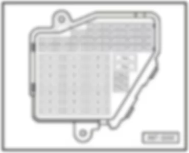
| No. | | Current Flow Diagram designation | Nominal value | | Function/component | Terminal |
| A | - | Fuse 1 on fuse holder B -SB1- | 15 A | - | Clutch pedal switch -F36- (BWE) | 30 |
| | | | | | Brake pedal switch -F47- (BWE) | |
| | | | | | Map-controlled engine cooling system thermostat -F265- (ALZ and CFMA) | |
| | | | | | Inlet camshaft control valve 1 -N205- (BWE and CFMA) | |
| | | | 20 A | - | Relay for supplementary fuel pump -J832- (CAGA, CAGC and CAHA) | |
| | | | | | Ignition coil 1 with output stage -N70- (CDHA, CDHB and CDND) | |
| | | | | | Ignition coil 2 with output stage -N127- (CDHA, CDHB and CDND) | |
| | | | | | Ignition coil 3 with output stage -N291- (CDHA, CDHB and CDND) | |
| | | | | | Ignition coil 4 with output stage -N292- (CDHA, CDHB and CDND) | |
| B | - | Fuse 2 on fuse holder B -SB2- | 15 A | - | Charge pressure control solenoid valve -N75- (BWE) | 30 |
| | | | | | Activated charcoal filter system solenoid valve 1 -N80- (BWE) | |
| | | | | | Turbocharger air recirculation valve -N249- (BWE) | |
| | | | | | Fuel pressure regulating valve -N276- (BWE) | |
| | | | 40 A | - | Secondary air pump relay -J299- (ALZ and CFMA) | |
| | | | 60 A | - | Automatic glow period control unit -J179- (CAGA, CAGC and CAHA) | |
| C | - | Fuse 3 on fuse holder B -SB3- | 15 A | - | Clutch pedal switch -F36- (CAGA, CAGC and CAHA) | 30 |
| | | | | | Brake pedal switch -F47- (CAGA, CAGC and CAHA) | |
| | | | | | Automatic glow period control unit -J179- (CAGA, CAGC and CAHA) | |
| | | | | | Low heat output relay -J359- (CAGA, CAGC and CAHA) | |
| | | | | | High heat output relay -J360- (CAGA, CAGC and CAHA) | |
| | | | | | Engine control unit -J623- (BWE) | |
| | | | | | Charge pressure control solenoid valve -N75- (CAGA, CAGC and CAHA) | |
| | | | | | Heater element for crankcase breather -N79- (CAGA, CAGC and CAHA) (only models for cold climate countries) | |
| | | | | | Exhaust gas recirculation cooler change-over valve -N345- (CAGA, CAGC and CAHA) | |
| | | | | | Lambda probe heater -Z19- (CDHA, CDHB and CDND) | |
| | | | | | Lambda probe 1 heater after catalytic converter -Z29- (CDHA, CDHB and CDND) | |
| D | - | Fuse 4 on fuse holder B -SB4- | 15 A | - | Engine control unit -J623- (CAGA, CAGC, CAHA, CDHA, CDHB and CDND) | 30 |
| | | | 20 A | | Engine control unit -J623- (ALZ and CFMA) | |
| | | | | | Ignition coil 1 with output stage -N70- (BWE and CFMA) | |
| | | | | | Ignition coil 2 with output stage -N127- (BWE and CFMA) | |
| | | | | | Ignition transformer -N152- (ALZ) | |
| | | | | | Ignition coil 3 with output stage -N291- (BWE and CFMA) | |
| | | | | | Ignition coil 4 with output stage -N292- (BWE and CFMA) | |
| E | - | Fuse 5 on fuse holder B -SB5- | 10 A | | Clutch pedal switch -F36- (CDHA and CDHB) | 30 |
| | | | | | Brake pedal switch -F47- (CDHA and CDHB) | |
| | | | | | Additional coolant pump relay -J496- (CDHA and CDHB) | |
| | | | | | Charge pressure control solenoid valve -N75- (CDHA and CDHB) | |
| | | | | | Activated charcoal filter system solenoid valve 1 -N80- (CDHA and CDHB) | |
| | | | | | Inlet camshaft control valve 1 -N205- (CDHA and CDHB) | |
| | | | | | Turbocharger air recirculation valve -N249- (CDHA and CDHB) | |
| | | | | | Intake manifold flap valve -N316- (CDHA and CDHB) | |
| | | | | | Oil pressure warning lamp -N428- (CDHA and CDHB) | |
| | | | 15 A | - | Clutch pedal switch -F36- (CDND) | |
| | | | | | Brake pedal switch -F47- (CDND) | |
| | | | | | Actuator 1 for camshaft adjustment -F366- (CDND) | |
| | | | | | Actuator 2 for camshaft adjustment -F367- (CDND) | |
| | | | | | Actuator 3 for camshaft adjustment -F368- (CDND) | |
| | | | | | Actuator 4 for camshaft adjustment -F369- (CDND) | |
| | | | | | Actuator 5 for camshaft adjustment -F370- (CDND) | |
| | | | | | Actuator 6 for camshaft adjustment -F371- (CDND) | |
| | | | | | Actuator 7 for camshaft adjustment -F372- (CDND) | |
| | | | | | Actuator 8 for camshaft adjustment -F373- (CDND) | |
| | | | | | Additional coolant pump relay -J496- (CDND) | |
| | | | | | Injector, cylinder 1 -N30- (ALZ and CFMA) | |
| | | | | | Injector, cylinder 2 -N31- (ALZ and CFMA) | |
| | | | | | Injector, cylinder 3 -N32- (ALZ and CFMA) | |
| | | | | | Injector, cylinder 4 -N33- (ALZ and CFMA) | |
| | | | | | Charge pressure control solenoid valve -N75- (CDND) | |
| | | | | | Activated charcoal filter system solenoid valve 1 -N80- (CDND) | |
| | | | | | Inlet camshaft control valve 1 -N205- (CDND) | |
| | | | | | Turbocharger air recirculation valve -N249- (CDND) | |
| | | | | | Intake manifold flap valve -N316- (CDND) | |
| | | | | | Oil pressure warning lamp -N428- (CDND) | |
| | | | | | Pump for exhaust gas recirculation cooler -V400- (CAGA, CAGC and CAHA) | |
| | | | | | Lambda probe heater -Z19- (BWE) | |
| | | | | | Lambda probe 1 heater after catalytic converter -Z29- (BWE) | |
| F | - | Fuse 6 on fuse holder B -SB6- | 5 A | - | Engine control unit -J623- (CAGA, CAGC, CAHA, CDHA, CDHB and CDND) | 30 |
| G | - | Fuse 7 on fuse holder B -SB7- | 10 A | - | Fuel pressure regulating valve -N276- (CAGA, CAGC, CAHA and CDND) | 30 |
| | | | | | Fuel metering valve -N290- (CAGA, CAGC and CAHA) | |
| | | | 15 A | - | Air mass meter -G70- (ALZ and CFMA) | |
| | | | | | Automatic gearbox control unit -J217- (BWE) | |
| | | | | | Secondary air pump relay -J299- (ALZ and CFMA) | |
| | | | | | Activated charcoal filter system solenoid valve 1 -N80- (ALZ and CFMA) | |
| | | | | | Secondary air inlet valve -N112- (CFMA) | |
| | | | | | Variable intake manifold change-over valve -N156- (ALZ) | |
| | | | | | Turbocharger air recirculation valve -N249- (CFMA) | |
| | | | | | Lambda probe heater -Z19- (ALZ and CFMA) | |
| | | | | | Lambda probe 1 heater after catalytic converter -Z29- (ALZ and CFMA) | |
| | | | 20 A | - | Fuel pressure regulating valve -N276- (CDHA and CDHB) | |
| No. | | Current Flow Diagram designation | Nominal value | | Function/component | Terminal |
| A | - | Fuse 1 on fuse holder B -SB1- | 15 A | - | Clutch pedal switch -F36- (BWE) | 30 |
| | | | | | Brake pedal switch -F47- (BWE) | |
| | | | | | Inlet camshaft control valve 1 -N205- (BWE) | |
| | | | 20 A | - | Ignition coil 1 with output stage -N70- (CDHA, CDHB and CDND) | |
| | | | | | Ignition coil 2 with output stage -N127- (CDHA, CDHB and CDND) | |
| | | | | | Ignition coil 3 with output stage -N291- (CDHA, CDHB and CDND) | |
| | | | | | Ignition coil 4 with output stage -N292- (CDHA, CDHB and CDND) | |
| B | - | Fuse 2 on fuse holder B -SB2- | 15 A | - | Charge pressure control solenoid valve -N75- (BWE) | 30 |
| | | | | | Activated charcoal filter system solenoid valve 1 -N80- (BWE) | |
| | | | | | Turbocharger air recirculation valve -N249- (BWE) | |
| | | | | | Fuel pressure regulating valve -N276- (BWE) | |
| | | | 60 A | - | Automatic glow period control unit -J179- (CGLB, CJCA and CJCC) | |
| C | - | Fuse 3 on fuse holder B -SB3- | 15 A | - | Clutch pedal switch -F36- (CGLB, CJCA and CJCC) | 30 |
| | | | | | Brake pedal switch -F47- (CGLB, CJCA and CJCC) | |
| | | | | | Air mass meter -G70- (CGLB, CJCA and CJCC) | |
| | | | | | Automatic glow period control unit -J179- (CGLB, CJCA and CJCC) | |
| | | | | | Low heat output relay -J359- (CGLB, CJCA and CJCC) | |
| | | | | | High heat output relay -J360- (CGLB, CJCA and CJCC) | |
| | | | | | Engine control unit -J623- (BWE) | |
| | | | | | Charge pressure control solenoid valve -N75- (CGLB, CJCA and CJCC) | |
| | | | | | Heater element for crankcase breather -N79- (CGLB, CJCA and CJCC) (only models for cold climate countries) | |
| | | | | | Exhaust gas recirculation cooler change-over valve -N345- (CGLB, CJCA and CJCC) | |
| | | | | | Lambda probe heater -Z19- (CDHA, CDHB and CDND) | |
| | | | | | Lambda probe 1 heater after catalytic converter -Z29- (CDHA, CDHB and CDND) | |
| D | - | Fuse 4 on fuse holder B -SB4- | 15 A | - | Engine control unit -J623- (CDHA, CDHB, CDND,CGLB, CJCA and CJCC) | 30 |
| | | | 20 A | | Ignition coil 1 with output stage -N70- (BWE) | |
| | | | | | Ignition coil 2 with output stage -N127- (BWE) | |
| | | | | | Ignition coil 3 with output stage -N291- (BWE) | |
| | | | | | Ignition coil 4 with output stage -N292- (BWE) | |
| E | - | Fuse 5 on fuse holder B -SB5- | 10 A | | Clutch pedal switch -F36- (CDHA and CDHB) | 30 |
| | | | | | Brake pedal switch -F47- (CDHA and CDHB) | |
| | | | | | Additional coolant pump relay -J496- (CDHA and CDHB) | |
| | | | | | Charge pressure control solenoid valve -N75- (CDHA and CDHB) | |
| | | | | | Activated charcoal filter system solenoid valve 1 -N80- (CDHA and CDHB) | |
| | | | | | Inlet camshaft control valve 1 -N205- (CDHA and CDHB) | |
| | | | | | Turbocharger air recirculation valve -N249- (CDHA and CDHB) | |
| | | | | | Intake manifold flap valve -N316- (CDHA and CDHB) | |
| | | | | | Oil pressure warning lamp -N428- (CDHA and CDHB) | |
| | | | 15 A | - | Clutch pedal switch -F36- (CDND) | |
| | | | | | Brake pedal switch -F47- (CDND) | |
| | | | | | Actuator 1 for camshaft adjustment -F366- (CDND) | |
| | | | | | Actuator 2 for camshaft adjustment -F367- (CDND) | |
| | | | | | Actuator 3 for camshaft adjustment -F368- (CDND) | |
| | | | | | Actuator 4 for camshaft adjustment -F369- (CDND) | |
| | | | | | Actuator 5 for camshaft adjustment -F370- (CDND) | |
| | | | | | Actuator 6 for camshaft adjustment -F371- (CDND) | |
| | | | | | Actuator 7 for camshaft adjustment -F372- (CDND) | |
| | | | | | Actuator 8 for camshaft adjustment -F373- (CDND) | |
| | | | | | Additional coolant pump relay -J496- (CDND) | |
| | | | | | Charge pressure control solenoid valve -N75- (CDND) | |
| | | | | | Activated charcoal filter system solenoid valve 1 -N80- (CDND) | |
| | | | | | Inlet camshaft control valve 1 -N205- (CDND) | |
| | | | | | Turbocharger air recirculation valve -N249- (CDND) | |
| | | | | | Intake manifold flap valve -N316- (CDND) | |
| | | | | | Oil pressure warning lamp -N428- (CDND) | |
| | | | | | Pump for exhaust gas recirculation cooler -V400- (CGLB, CJCA and CJCC) | |
| | | | | | Lambda probe heater -Z19- (BWE) | |
| | | | | | Lambda probe 1 heater after catalytic converter -Z29- (BWE) | |
| F | - | Fuse 6 on fuse holder B -SB6- | 5 A | - | Engine control unit -J623- (CDHA, CDHB, CDND, CGLB, CJCA and CJCC) | 30 |
| G | - | Fuse 7 on fuse holder B -SB7- | 10 A | - | Fuel pressure regulating valve -N276- (CDND, CGLB, CJCA and CJCC) | 30 |
| | | | | | Fuel metering valve -N290- (CGLB, CJCA and CJCC) | |
| | | | 15 A | - | Automatic gearbox control unit -J217- (BWE) | |
| | | | 20 A | - | Fuel pressure regulating valve -N276- (CDHA and CDHB) | |
| No. | | Current Flow Diagram designation | Nominal value | | Function/component | Terminal |
| A | - | Fuse 1 on fuse holder B -SB1- | 15 A | - | Clutch pedal switch -F36- (BWE) | 30 |
| | | | | | Brake pedal switch -F47- (BWE) | |
| | | | | | Map-controlled engine cooling system thermostat -F265- (ALZ and CFMA) | |
| | | | | | Engine control unit -J623- (CDHA, CDHB and CDND) | |
| | | | | | Inlet camshaft control valve 1 -N205- (BWE and CFMA) | |
| | | | 20 A | - | Relay for supplementary fuel pump -J832- (CAGA, CAGC and CAHA) | |
| B | - | Fuse 2 on fuse holder B -SB2- | 15 A | - | Charge pressure control solenoid valve -N75- (BWE) | 30 |
| | | | | | Activated charcoal filter system solenoid valve 1 -N80- (BWE) | |
| | | | | | Turbocharger air recirculation valve -N249- (BWE) | |
| | | | | | Fuel pressure regulating valve -N276- (BWE) | |
| | | | | | Pump for exhaust gas recirculation cooler -V400- (CAGA, CAGC and CAHA) | |
| | | | 20 A | - | Ignition coil 1 with output stage -N70- (CDHA, CDHB and CDND) | |
| | | | | | Ignition coil 2 with output stage -N127- (CDHA, CDHB and CDND) | |
| | | | | | Ignition coil 3 with output stage -N291- (CDHA, CDHB and CDND) | |
| | | | | - | Ignition coil 4 with output stage -N292- (CDHA, CDHB and CDND) | |
| C | - | Fuse 3 on fuse holder B -SB3- | 15 A | - | Clutch pedal switch -F36- (CAGA, CAGC and CAHA) | 30 |
| | | | | | Brake pedal switch -F47- (CAGA, CAGC and CAHA) | |
| | | | | | Automatic glow period control unit -J179- (CAGA, CAGC and CAHA) | |
| | | | | | Low heat output relay -J359- (CAGA, CAGC and CAHA) | |
| | | | | | High heat output relay -J360- (CAGA, CAGC and CAHA) | |
| | | | | | Engine control unit -J623- (BWE) | |
| | | | | | Charge pressure control solenoid valve -N75- (CAGA, CAGC and CAHA) | |
| | | | | | Exhaust gas recirculation cooler change-over valve -N345- (CAGA, CAGC and CAHA) | |
| | | | | | Lambda probe heater -Z19- (CDHA, CDHB and CDND) | |
| | | | | | Lambda probe 1 heater after catalytic converter -Z29- (CDHA, CDHB and CDND) | |
| D | - | Fuse 4 on fuse holder B -SB4- | 5 A | - | Engine control unit -J623- (CAGA, CAGC, CAHA, CDHA, CDHB and CDND) | 30 |
| | | | 20 A | - | Engine control unit -J623- (ALZ and CFMA) | |
| | | | | | Ignition coil 1 with output stage -N70- (BWE and CFMA) | |
| | | | | | Ignition coil 2 with output stage -N127- (BWE and CFMA) | |
| | | | | | Ignition transformer -N152- (ALZ) | |
| | | | | | Ignition coil 3 with output stage -N291- (BWE and CFMA) | |
| | | | | | Ignition coil 4 with output stage -N292- (BWE and CFMA) | |
| E | - | Fuse 5 on fuse holder B -SB5- | 10 A | - | Fuel pressure regulating valve -N276- (CAGA, CAGC, CAHA and CDND) | 30 |
| | | | | | Fuel metering valve -N290- (CAGA, CAGC and CAHA) | |
| | | | 15 A | - | Injector, cylinder 1 -N30- (ALZ and CFMA) | |
| | | | | | Injector, cylinder 2 -N31- (ALZ and CFMA) | |
| | | | | | Injector, cylinder 3 -N32- (ALZ and CFMA) | |
| | | | | | Injector, cylinder 4 -N33- (ALZ and CFMA) | |
| | | | | | Lambda probe heater -Z19- (BWE) | |
| | | | | | Lambda probe 1 heater after catalytic converter -Z29- (BWE) | |
| | | | 20 A | - | Fuel pressure regulating valve -N276- (CDHA and CDHB) | |
| F | - | Fuse 6 on fuse holder B -SB6- | 40 A | - | Secondary air pump relay -J299- (ALZ and CFMA) | 30 |
| | | | 60 A | - | Automatic glow period control unit -J179- (CAGA, CAGC and CAHA) | |
| G | - | Fuse 7 on fuse holder B -SB7- | 10 A | - | Clutch pedal switch -F36- (CDHA and CDHB) | 30 |
| | | | | | Brake pedal switch -F47- (CDHA and CDHB) | |
| | | | | | Charge pressure control solenoid valve -N75- (CDHA and CDHB) | |
| | | | | | Activated charcoal filter system solenoid valve 1 -N80- (CDHA and CDHB) | |
| | | | | | Inlet camshaft control valve 1 -N205- (CDHA and CDHB) | |
| | | | | | Turbocharger air recirculation valve -N249- (CDHA and CDHB) | |
| | | | | | Intake manifold flap valve -N316- (CDHA and CDHB) | |
| | | | | | Oil pressure warning lamp -N428- (CDHA and CDHB) | |
| | | | | | Additional coolant pump relay -J496- (CDHA and CDHB) | |
| | | | 15 A | - | Clutch pedal switch -F36- (CDND) | |
| | | | | | Brake pedal switch -F47- (CDND) | |
| | | | | | Actuator 1 for camshaft adjustment -F366- (CDND) | |
| | | | | | Actuator 2 for camshaft adjustment -F367- (CDND) | |
| | | | | | Actuator 3 for camshaft adjustment -F368- (CDND) | |
| | | | | | Actuator 4 for camshaft adjustment -F369- (CDND) | |
| | | | | | Actuator 5 for camshaft adjustment -F370- (CDND) | |
| | | | | | Actuator 6 for camshaft adjustment -F371- (CDND) | |
| | | | | | Actuator 7 for camshaft adjustment -F372- (CDND) | |
| | | | | | Actuator 8 for camshaft adjustment -F373- (CDND) | |
| | | | | | Air mass meter -G70- (ALZ and CFMA) | |
| | | | | | Automatic gearbox control unit -J217- (BWE) | |
| | | | | | Secondary air pump relay -J299- (ALZ and CFMA) | |
| | | | | | Additional coolant pump relay -J496- (CDND) | |
| | | | | | Engine control unit -J623- (CAGA, CAGC and CAHA) | |
| | | | | | Charge pressure control solenoid valve -N75- (CDND) | |
| | | | | | Activated charcoal filter system solenoid valve 1 -N80- (ALZ, CDND and CFMA) | |
| | | | | | Secondary air inlet valve -N112- (CFMA) | |
| | | | | | Variable intake manifold change-over valve -N156- (ALZ) | |
| | | | | | Inlet camshaft control valve 1 -N205- (CDND) | |
| | | | | | Turbocharger air recirculation valve -N249- (CDND and CFMA) | |
| | | | | | Lambda probe heater -Z19- (ALZ and CFMA) | |
| | | | | | Lambda probe 1 heater after catalytic converter -Z29- (ALZ and CFMA) | |
| No. | | Current Flow Diagram designation | Nominal value | | Function/component | Terminal |
| A | - | Fuse 1 on fuse holder B -SB1- | 15 A | - | Clutch pedal switch -F36- (BWE) | 30 |
| | | | | | Brake pedal switch -F47- (BWE) | |
| | | | | | Engine control unit -J623- (CDHA, CDHB and CDND) | |
| | | | | | Inlet camshaft control valve 1 -N205- (BWE) | |
| B | - | Fuse 2 on fuse holder B -SB2- | 15 A | - | Charge pressure control solenoid valve -N75- (BWE) | 30 |
| | | | | | Activated charcoal filter system solenoid valve 1 -N80- (BWE) | |
| | | | | | Turbocharger air recirculation valve -N249- (BWE) | |
| | | | | | Fuel pressure regulating valve -N276- (BWE) | |
| | | | | | Pump for exhaust gas recirculation cooler -V400- (CGLB, CJCA and CJCC) | |
| | | | 20 A | - | Ignition coil 1 with output stage -N70- (CDHA, CDHB and CDND) | |
| | | | | | Ignition coil 2 with output stage -N127- (CDHA, CDHB and CDND) | |
| | | | | | Ignition coil 3 with output stage -N291- (CDHA, CDHB and CDND) | |
| | | | | - | Ignition coil 4 with output stage -N292- (CDHA, CDHB and CDND) | |
| C | - | Fuse 3 on fuse holder B -SB3- | 15 A | - | Clutch pedal switch -F36- (CGLB, CJCA and CJCC) | 30 |
| | | | | | Brake pedal switch -F47- (CGLB, CJCA and CJCC) | |
| | | | | | Air mass meter -G70- (CGLB, CJCA and CJCC) | |
| | | | | | Automatic glow period control unit -J179- (CGLB, CJCA and CJCC) | |
| | | | | | Low heat output relay -J359- (CGLB, CJCA and CJCC) | |
| | | | | | High heat output relay -J360- (CGLB, CJCA and CJCC) | |
| | | | | | Engine control unit -J623- (BWE) | |
| | | | | | Charge pressure control solenoid valve -N75- (CGLB, CJCA and CJCC) | |
| | | | | | Exhaust gas recirculation cooler change-over valve -N345- (CGLB, CJCA and CJCC) | |
| | | | | | Lambda probe heater -Z19- (CDHA, CDHB and CDND) | |
| | | | | | Lambda probe 1 heater after catalytic converter -Z29- (CDHA, CDHB and CDND) | |
| D | - | Fuse 4 on fuse holder B -SB4- | 5 A | - | Engine control unit -J623- (CDHA, CDHB, CDND, CGLB, CJCA and CJCC) | 30 |
| | | | 20 A | - | Ignition coil 1 with output stage -N70- (BWE) | |
| | | | | | Ignition coil 2 with output stage -N127- (BWE) | |
| | | | | | Ignition coil 3 with output stage -N291- (BWE) | |
| | | | | | Ignition coil 4 with output stage -N292- (BWE) | |
| E | - | Fuse 5 on fuse holder B -SB5- | 10 A | - | Fuel pressure regulating valve -N276- (CDND, CGLB, CJCA and CJCC) | 30 |
| | | | | | Fuel metering valve -N290- (CGLB, CJCA and CJCC) | |
| | | | 15 A | - | Lambda probe heater -Z19- (BWE) | |
| | | | | | Lambda probe 1 heater after catalytic converter -Z29- (BWE) | |
| | | | 20 A | - | Fuel pressure regulating valve -N276- (CDHA and CDHB) | |
| F | - | Fuse 6 on fuse holder B -SB6- | 60 A | - | Automatic glow period control unit -J179- (CGLB, CJCA and CJCC) | 30 |
| G | - | Fuse 7 on fuse holder B -SB7- | 10 A | - | Clutch pedal switch -F36- (CDHA and CDHB) | 30 |
| | | | | | Brake pedal switch -F47- (CDHA and CDHB) | |
| | | | | | Charge pressure control solenoid valve -N75- (CDHA and CDHB) | |
| | | | | | Activated charcoal filter system solenoid valve 1 -N80- (CDHA and CDHB) | |
| | | | | | Inlet camshaft control valve 1 -N205- (CDHA and CDHB) | |
| | | | | | Turbocharger air recirculation valve -N249- (CDHA and CDHB) | |
| | | | | | Intake manifold flap valve -N316- (CDHA and CDHB) | |
| | | | | | Oil pressure warning lamp -N428- (CDHA and CDHB) | |
| | | | | | Additional coolant pump relay -J496- (CDHA and CDHB) | |
| | | | 15 A | - | Clutch pedal switch -F36- (CDND) | |
| | | | | | Brake pedal switch -F47- (CDND) | |
| | | | | | Actuator 1 for camshaft adjustment -F366- (CDND) | |
| | | | | | Actuator 2 for camshaft adjustment -F367- (CDND) | |
| | | | | | Actuator 3 for camshaft adjustment -F368- (CDND) | |
| | | | | | Actuator 4 for camshaft adjustment -F369- (CDND) | |
| | | | | | Actuator 5 for camshaft adjustment -F370- (CDND) | |
| | | | | | Actuator 6 for camshaft adjustment -F371- (CDND) | |
| | | | | | Actuator 7 for camshaft adjustment -F372- (CDND) | |
| | | | | | Actuator 8 for camshaft adjustment -F373- (CDND) | |
| | | | | | Automatic gearbox control unit -J217- (BWE) | |
| | | | | | Additional coolant pump relay -J496- (CDND) | |
| | | | | | Engine control unit -J623- (CGLB, CJCA and CJCC) | |
| | | | | | Charge pressure control solenoid valve -N75- (CDND) | |
| | | | | | Activated charcoal filter system solenoid valve 1 -N80- (CDND) | |
| | | | | | Inlet camshaft control valve 1 -N205- (CDND) | |
| | | | | | Turbocharger air recirculation valve -N249- (CDND) | |
| No. | | Current Flow Diagram designation | Nominal value | | Function/component | Terminal |
| 1 | - | Fuse 1 on fuse holder C -SC1- | 10 A | - | Climatronic control unit -J255- | 30 |
| 2 | - | Fuse 2 on fuse holder C -SC2- | 5 A | - | Left footwell light -W9- | 30 |
| | | | | | Right footwell light -W10- | |
| | | | | | Rear left footwell light -W45- | |
| | | | | | Rear right footwell light -W46- | |
| 3 | - | Fuse 3 on fuse holder C -SC3- | 5 A | - | Left washer jet heater element -Z20- | 75x |
| | | | | | Right washer jet heater element -Z21- | |
| 4 | - | Fuse 4 on fuse holder C -SC4- | 5 A | - | Radiator fan control unit -J293- | 87 |
| 5 | - | Fuse 5 on fuse holder C -SC5- | 10 A | - | Rear roller blind switch -E149- | 15 |
| | | | | | Tiptronic switch -F189- (BWE, CAGA, CAGC and CAHA) | |
| | | | | | Oil level and oil temperature sender -G266- (ALZ, BWE, CAGA, CAGC, CAHA, CDHA, CDHB, CDND and CFMA) | |
| | | | | | Parking aid control unit -J446- | |
| | | | | | Tyre pressure monitor control unit -J502- | |
| 6 | - | Fuse 6 on fuse holder C -SC6- | 5 A | - | High pressure sender -G65- | 15 |
| | | | | | Air quality sensor -G238- | |
| 7 | - | Fuse 7 on fuse holder C -SC7- | 10 A | - | Traction control system switch -E132- | 15 |
| | | | | | Clutch pedal switch -F36- (ALZ and CFMA) | |
| | | | | | Brake pedal switch -F47- (ALZ and CFMA) | |
| | | | | | ESP sensor unit -G419- | |
| | | | | | ABS control unit -J104- | |
| 8 | - | Fuse 8 on fuse holder C -SC8- | 5 A | - | Aerial connection -R1- | 30 |
| | | | | | Telephone transmitter and receiver unit -R36- | |
| | | | | | Aerial amplifier for mobile telephone -R86- (up to April 2009) | |
| 9 | - | Fuse 9 on fuse holder C -SC9- | - | - | vacant | |
| 10 | - | Fuse 10 on fuse holder C -SC10- | 5 A | - | Headlight range control regulator -E102- | 15 |
| | | | | | Power output module for right headlight -J668- | |
| | | | | | Cornering light and headlight range control unit -J745- | |
| | | | | | Left headlight range control motor -V48- | |
| | | | | | Right headlight range control motor -V49- | |
| 11 | - | Fuse 11 on fuse holder C -SC11- | 5 A | - | Airbag control unit -J234- | 15 |
| | | | | | Front passenger side airbag deactivated warning lamp -K145- | |
| 12 | - | Fuse 12 on fuse holder C -SC12- | 10 A | - | Diagnostic connection -T16/16- | 30 |
| 13 | - | Fuse 13 on fuse holder C -SC13- | 10 A | - | Steering column electronics control unit -J527- | 30 |
| 14 | - | Fuse 14 on fuse holder C -SC14- | 10 A | - | Brake light switch -F- | 30 |
| 15 | - | Fuse 15 on fuse holder C -SC15- | 10 A | - | Control unit in dash panel insert -J285- | 30 |
| 16 | - | Fuse 16 on fuse holder C -SC16- | 10 A | - | Rear roller blind control unit -J262- (from May 2010) | 30 |
| 17 | - | Fuse 17 on fuse holder C -SC17- | 10 A | - | Rain and light detector sensor -G397- | 30 |
| | | | | | Tyre pressure monitor control unit -J502- | |
| 18 | - | Fuse 18 on fuse holder C -SC18- | 5 A | - | Power output module for left headlight -J667- | 15 |
| 19 | - | Fuse 19 on fuse holder C -SC19- | - | - | vacant | |
| 20 | - | Fuse 20 on fuse holder C -SC20- | - | - | vacant | |
| 21 | - | Fuse 21 on fuse holder C -SC21- | - | - | vacant | |
| 22 | - | Fuse 22 on fuse holder C -SC22- | 15 A | - | Driver door control unit -J386- | 30 |
| | | | | | Front passenger door control unit -J387- | |
| 23 | - | Fuse 23 on fuse holder C -SC23- | 15 A | - | Rear left door control unit -J388- | 30 |
| | | | | | Rear right door control unit -J389- | |
| 24 | - | Fuse 24 on fuse holder C -SC24- | 20 A | - | Convenience system central control unit -J393- | 30 |
| 25 | - | Fuse 25 on fuse holder C -SC25- | 30 A | - | Fresh air blower control unit -J126- | 30 |
| 26 | - | Fuse 26 on fuse holder C -SC26- | 30 A | - | Heated rear window relay -J9- | 30 |
| 27 | - | Fuse 27 on fuse holder C -SC27- | 30 A | - | Trailer detector control unit -J345- | 30 |
| 28 | - | Fuse 28 on fuse holder C -SC28- | 20 A | - | Fuel system pressurisation pump -G6- (ALZ, CAGA, CAGC, CAHA and CFMA) | 87 |
| | | | | | Fuel pump control unit -J538- (BWE, CDHA, CDHB and CDND) | |
| 29 | - | Fuse 29 on fuse holder C -SC29- | - | - | vacant | |
| 30 | - | Fuse 30 on fuse holder C -SC30- | 20 A | - | Sliding sunroof adjustment control unit -J245- | 30 |
| 31 | - | Fuse 31 on fuse holder C -SC31- | 15 A | - | Reversing light switch -F4- | 15 |
| | | | | | Air mass meter -G70- (CAGA, CAGC and CAHA) | |
| | | | | | Light detector sensor -G399- | |
| | | | | | Automatic gearbox control unit -J217- (BWE, CAGA, CAGC and CAHA) | |
| | | | | | Diagnostic connection -T16/1- | |
| | | | | | Automatic anti-dazzle interior mirror -Y7- | |
| 32 | - | Fuse 32 on fuse holder C -SC32- | 15 A | - | Trailer socket -U10- | 75x |
| 33 | - | Fuse 33 on fuse holder C -SC33- | 20 A | - | Cigarette lighter -U1- | 75x |
| 34 | - | Fuse 34 on fuse holder C -SC34- | 5 A | - | Lambda probe heater -Z19- (CAGA, CAGC and CAHA) | 87 |
| 35 | - | Fuse 35 on fuse holder C -SC35- | 20 A | - | Electric socket -U- | 75x |
| 36 | - | Fuse 36 on fuse holder C -SC36- | 30 A | - | Onboard supply control unit -J519- T10b/5 | 75x |
| | | | | | Windscreen wiper motor -V- | |
| | | | | | Rear window wiper motor -V12- (Exeo ST) | |
| 37 | - | Fuse 37 on fuse holder C -SC37- | 30 A | - | Onboard supply control unit -J519- T10b/10 | 75x |
| | | | | | Washer pump -V5- | |
| | | | | | Headlight washer system pump -V11- | |
| 38 | - | Fuse 38 on fuse holder C -SC38- | 15 A | - | Interior monitor send and receive module 1 -G303- | 30 |
| | | | | | Alarm horn -H12- | |
| | | | | | Convenience system central control unit -J393- | |
| 39 | - | Fuse 39 on fuse holder C -SC39- | 20 A | - | Navigation system with CD drive control unit -J401- | 30 |
| | | | | | Control unit with display for radio and navigation system -J503- | |
| | | | | | Radio -R- | |
| | | | | | Amplifier -R12- | |
| 40 | - | Fuse 40 on fuse holder C -SC40- | 25 A | - | Treble tone horn -H2- | 30 |
| | | | | | Bass tone horn -H7- | |
| | | | | | Dual tone horn relay -J4- | |
| 41 | - | Fuse 41 on fuse holder C -SC41- | 30 A | - | Transformer with socket, 12 V - 230 V -U13- | 30 |
| 42 | - | Fuse 42 on fuse holder C -SC42- | 25 A | - | ABS control unit -J104- | 30 |
| 43 | - | Fuse 43 on fuse holder C -SC43- | 15 A | - | Air mass meter -G70- (BWE, CDHA, CDHB and CDND) | 15 |
| | | | | | Current supply relay for Simos control unit -J363- (ALZ) | |
| | | | | | Engine control unit -J623- (ALZ, BWE, CAGA, CAGC, CAHA, CDHA, CDHB, CDND and CFMA) | |
| | | | | | Exhaust gas recirculation valve -N18- (ALZ) | |
| | | | | | Charge pressure control solenoid valve -N75- (CFMA) | |
| 44 | - | Fuse 44 on fuse holder C -SC44- | 35 A | - | Climatronic control unit -J255- (seat heater supply) | 30 |
| No. | | Current Flow Diagram designation | Nominal value | | Function/component | Terminal |
| 1 | - | Fuse 1 on fuse holder C -SC1- | 10 A | - | Climatronic control unit -J255- | 30 |
| 2 | - | Fuse 2 on fuse holder C -SC2- | 5 A | - | Left footwell light -W9- | 30 |
| | | | | | Right footwell light -W10- | |
| | | | | | Rear left footwell light -W45- | |
| | | | | | Rear right footwell light -W46- | |
| 3 | - | Fuse 3 on fuse holder C -SC3- | 5 A | - | Left washer jet heater element -Z20- | 75x |
| | | | | | Right washer jet heater element -Z21- | |
| 4 | - | Fuse 4 on fuse holder C -SC4- | 5 A | - | Radiator fan control unit -J293- | 87 |
| 5 | - | Fuse 5 on fuse holder C -SC5- | 10 A | - | Rear roller blind switch -E149- | 15 |
| | | | | | Tiptronic switch -F189- (BWE and CJCA) | |
| | | | | | Oil level and oil temperature sender -G266- | |
| | | | | | Parking aid control unit -J446- | |
| | | | | | Tyre pressure monitor control unit -J502- | |
| 6 | - | Fuse 6 on fuse holder C -SC6- | 5 A | - | High pressure sender -G65- | 15 |
| | | | | | Air quality sensor -G238- | |
| 7 | - | Fuse 7 on fuse holder C -SC7- | 10 A | - | Traction control system switch -E132- | 15 |
| | | | | | ESP sensor unit -G419- | |
| | | | | | ABS control unit -J104- | |
| 8 | - | Fuse 8 on fuse holder C -SC8- | 5 A | - | Telephone transmitter and receiver unit -R36- | 30 |
| 9 | - | Fuse 9 on fuse holder C -SC9- | - | - | vacant | |
| 10 | - | Fuse 10 on fuse holder C -SC10- | 5 A | - | Headlight range control regulator -E102- | 15 |
| | | | | | Power output module for right headlight -J668- | |
| | | | | | Cornering light and headlight range control unit -J745- | |
| | | | | | Left headlight range control motor -V48- | |
| | | | | | Right headlight range control motor -V49- | |
| 11 | - | Fuse 11 on fuse holder C -SC11- | 5 A | - | Airbag control unit -J234- | 15 |
| | | | | | Front passenger side airbag deactivated warning lamp -K145- | |
| 12 | - | Fuse 12 on fuse holder C -SC12- | 10 A | - | Diagnostic connection -T16/16- | 30 |
| 13 | - | Fuse 13 on fuse holder C -SC13- | 10 A | - | Steering column electronics control unit -J527- | 30 |
| 14 | - | Fuse 14 on fuse holder C -SC14- | 10 A | - | Brake light switch -F- | 30 |
| 15 | - | Fuse 15 on fuse holder C -SC15- | 10 A | - | Control unit in dash panel insert -J285- | 30 |
| 16 | - | Fuse 16 on fuse holder C -SC16- | 10 A | - | Rear roller blind control unit -J262- | 30 |
| 17 | - | Fuse 17 on fuse holder C -SC17- | 10 A | - | Rain and light detector sensor -G397- | 30 |
| | | | | | Tyre pressure monitor control unit -J502- | |
| 18 | - | Fuse 18 on fuse holder C -SC18- | 5 A | - | Power output module for left headlight -J667- | 15 |
| 19 | - | Fuse 19 on fuse holder C -SC19- | - | - | vacant | |
| 20 | - | Fuse 20 on fuse holder C -SC20- | - | - | vacant | |
| 21 | - | Fuse 21 on fuse holder C -SC21- | - | - | vacant | |
| 22 | - | Fuse 22 on fuse holder C -SC22- | 15 A | - | Driver door control unit -J386- | 30 |
| | | | | | Front passenger door control unit -J387- | |
| 23 | - | Fuse 23 on fuse holder C -SC23- | 15 A | - | Rear left door control unit -J388- | 30 |
| | | | | | Rear right door control unit -J389- | |
| 24 | - | Fuse 24 on fuse holder C -SC24- | 20 A | - | Convenience system central control unit -J393- | 30 |
| 25 | - | Fuse 25 on fuse holder C -SC25- | 30 A | - | Fresh air blower control unit -J126- | 30 |
| 26 | - | Fuse 26 on fuse holder C -SC26- | 30 A | - | Heated rear window relay -J9- | 30 |
| 27 | - | Fuse 27 on fuse holder C -SC27- | 30 A | - | Trailer detector control unit -J345- | 30 |
| 28 | - | Fuse 28 on fuse holder C -SC28- | 20 A | - | Fuel pump control unit -J538- | 87 |
| 29 | - | Fuse 29 on fuse holder C -SC29- | - | - | vacant | |
| 30 | - | Fuse 30 on fuse holder C -SC30- | 20 A | - | Sliding sunroof adjustment control unit -J245- | 30 |
| 31 | - | Fuse 31 on fuse holder C -SC31- | 15 A | - | Reversing light switch -F4- | 15 |
| | | | | | Light detector sensor -G399- | |
| | | | | | Automatic gearbox control unit -J217- (BWE and CJCA) | |
| | | | | | Diagnostic connection -T16/1- | |
| | | | | | Automatic anti-dazzle interior mirror -Y7- | |
| 32 | - | Fuse 32 on fuse holder C -SC32- | 15 A | - | Trailer socket -U10- | 75x |
| 33 | - | Fuse 33 on fuse holder C -SC33- | 20 A | - | Cigarette lighter -U1- | 75x |
| 34 | - | Fuse 34 on fuse holder C -SC34- | 10 A | - | Lambda probe heater -Z19- (CGLB, CJCA and CJCC) | 87 |
| 35 | - | Fuse 35 on fuse holder C -SC35- | 20 A | - | Electric socket -U- | 75x |
| 36 | - | Fuse 36 on fuse holder C -SC36- | 30 A | - | Onboard supply control unit -J519- T10b/5 | 75x |
| | | | | | Windscreen wiper motor -V- | |
| | | | | | Rear window wiper motor -V12- (Exeo ST) | |
| 37 | - | Fuse 37 on fuse holder C -SC37- | 30 A | - | Onboard supply control unit -J519- T10b/10 | 75x |
| | | | | | Washer pump -V5- | |
| | | | | | Headlight washer system pump -V11- | |
| 38 | - | Fuse 38 on fuse holder C -SC38- | 15 A | - | Interior monitor send and receive module 1 -G303- | 30 |
| | | | | | Alarm horn -H12- | |
| | | | | | Convenience system central control unit -J393- | |
| 39 | - | Fuse 39 on fuse holder C -SC39- | 20 A | - | Navigation system with CD drive control unit -J401- | 30 |
| | | | | | Radio -R- | |
| | | | | | Amplifier -R12- | |
| 40 | - | Fuse 40 on fuse holder C -SC40- | 25 A | - | Treble tone horn -H2- | 30 |
| | | | | | Bass tone horn -H7- | |
| | | | | | Dual tone horn relay -J4- | |
| 41 | - | Fuse 41 on fuse holder C -SC41- | 30 A | - | Transformer with socket, 12 V - 230 V -U13- | 30 |
| 42 | - | Fuse 42 on fuse holder C -SC42- | 25 A | - | ABS control unit -J104- | 30 |
| 43 | - | Fuse 43 on fuse holder C -SC43- | 15 A | - | Air mass meter -G70- (BWE, CDHA, CDHB and CDND) | 15 |
| | | | | | Engine control unit -J623- | |
| 44 | - | Fuse 44 on fuse holder C -SC44- | 35 A | - | Climatronic control unit -J255- (seat heater supply) | 30 |
| No. | | Current Flow Diagram designation | Nominal value | | Function/component | Terminal |
| 1 | - | Fuse 1 on fuse holder C -SC1- | 10 A | - | Climatronic control unit -J255- | 30 |
| 2 | - | Fuse 2 on fuse holder C -SC2- | 5 A | - | Left footwell light -W9- | 30 |
| | | | | | Right footwell light -W10- | |
| | | | | | Rear left footwell light -W45- | |
| | | | | | Rear right footwell light -W46- | |
| 3 | - | Fuse 3 on fuse holder C -SC3- | 5 A | - | Left washer jet heater element -Z20- | 75x |
| | | | | | Right washer jet heater element -Z21- | |
| 4 | - | Fuse 4 on fuse holder C -SC4- | 5 A | - | Radiator fan control unit -J293- | 87 |
| 5 | - | Fuse 5 on fuse holder C -SC5- | 10 A | - | Rear roller blind switch -E149- | 15 |
| | | | | | Tiptronic switch -F189- (BWE and CJCA) | |
| | | | | | Oil level and oil temperature sender -G266- | |
| | | | | | Parking aid control unit -J446- | |
| | | | | | Tyre pressure monitor control unit -J502- | |
| | | | | | Voltage stabiliser -J532- (with stop/start system only) | |
| | | | | | Data bus diagnostic interface -J533- (with stop/start system only) | |
| | | | | | Transformer with socket, 12 V - 230 V -U13- (with stop/start system only) | |
| 6 | - | Fuse 6 on fuse holder C -SC6- | 5 A | - | Stop/start system button -E693- (with stop/start system only) | 15 |
| | | | | | High pressure sender -G65- | |
| | | | | | Air quality sensor -G238- | |
| | | | | | Button illumination bulb -L76- (with stop/start system only) | |
| 7 | - | Fuse 7 on fuse holder C -SC7- | 10 A | - | Traction control system switch -E132- | 15 |
| | | | | | ESP sensor unit -G419- | |
| | | | | | ABS control unit -J104- | |
| 8 | - | Fuse 8 on fuse holder C -SC8- | 5 A | - | Telephone transmitter and receiver unit -R36- | 30 |
| 9 | - | Fuse 9 on fuse holder C -SC9- | 10 A | - | Lambda probe heater -Z19- (CGLB, CJCA and CJCC) | 87 |
| 10 | - | Fuse 10 on fuse holder C -SC10- | 5 A | - | Headlight range control regulator -E102- | 15 |
| | | | | | Power output module for right headlight -J668- | |
| | | | | | Cornering light and headlight range control unit -J745- | |
| | | | | | Left headlight range control motor -V48- | |
| | | | | | Right headlight range control motor -V49- | |
| 11 | - | Fuse 11 on fuse holder C -SC11- | 5 A | - | Airbag control unit -J234- | 15 |
| | | | | | Front passenger side airbag deactivated warning lamp -K145- | |
| 12 | - | Fuse 12 on fuse holder C -SC12- | 10 A | - | Diagnostic connection -T16/16- | 30 |
| 13 | - | Fuse 13 on fuse holder C -SC13- | 10 A | - | Steering column electronics control unit -J527- | 30 |
| 14 | - | Fuse 14 on fuse holder C -SC14- | 10 A | - | Brake light switch -F- | 30 |
| 15 | - | Fuse 15 on fuse holder C -SC15- | 10 A | - | Control unit in dash panel insert -J285- (without stop/start system only) | 30 |
| | | | | | Data bus diagnostic interface -J533- (with stop/start system only) | |
| 16 | - | Fuse 16 on fuse holder C -SC16- | 10 A | - | Rear roller blind control unit -J262- | 30 |
| 17 | - | Fuse 17 on fuse holder C -SC17- | 10 A | - | Rain and light detector sensor -G397- | 30 |
| | | | | | Tyre pressure monitor control unit -J502- | |
| 18 | - | Fuse 18 on fuse holder C -SC18- | 5 A | - | Power output module for left headlight -J667- | 15 |
| 19 | - | Fuse 19 on fuse holder C -SC19- | 10 A | - | Control unit in dash panel insert -J285- (with stop/start system only) | 30 |
| 20 | - | Fuse 20 on fuse holder C -SC20- | 15 A | - | Air mass meter -G70- (BWE, CDHA, CDHB and CDND) | 15 |
| | | | | | Engine control unit -J623- | |
| 21 | - | Fuse 21 on fuse holder C -SC21- | 5 A | - | Battery monitor control unit -J367- (with stop/start system only) | 30 |
| 22 | - | Fuse 22 on fuse holder C -SC22- | - | - | vacant | |
| 23 | - | Fuse 23 on fuse holder C -SC23- | - | - | vacant | |
| 24 | - | Fuse 24 on fuse holder C -SC24- | 20 A | - | Convenience system central control unit -J393- | 30 |
| 25 | - | Fuse 25 on fuse holder C -SC25- | 30 A | - | Fresh air blower control unit -J126- | 30 |
| 26 | - | Fuse 26 on fuse holder C -SC26- | 30 A | - | Heated rear window relay -J9- | 30 |
| 27 | - | Fuse 27 on fuse holder C -SC27- | 30 A | - | Trailer detector control unit -J345- | 30 |
| 28 | - | Fuse 28 on fuse holder C -SC28- | 20 A | - | Fuel pump control unit -J538- | 87 |
| 29 | - | Fuse 29 on fuse holder C -SC29- | 20 A | - | Navigation system with CD drive control unit -J401- (with stop/start system only) | 30 |
| | | | | | Control unit with display for radio and navigation system -J503- (with stop/start system only) | |
| | | | | | Radio -R- (with stop/start system only) | |
| | | | | | Amplifier -R12- (with stop/start system only) | |
| 30 | - | Fuse 30 on fuse holder C -SC30- | 20 A | - | Sliding sunroof adjustment control unit -J245- | 30 |
| 31 | - | Fuse 31 on fuse holder C -SC31- | 15 A | - | Reversing light switch -F4- | 15 |
| | | | | | Light detector sensor -G399- | |
| | | | | | Automatic gearbox control unit -J217- (BWE and CJCA) | |
| | | | | | Diagnostic connection -T16/1- | |
| | | | | | Automatic anti-dazzle interior mirror -Y7- | |
| 32 | - | Fuse 32 on fuse holder C -SC32- | 15 A | - | Trailer socket -U10- | 75x |
| 33 | - | Fuse 33 on fuse holder C -SC33- | 20 A | - | Cigarette lighter -U1- | 75x |
| 34 | - | Fuse 34 on fuse holder C -SC34- | 30 A | - | Driver door control unit -J386- | 30 |
| | | | | | Front passenger door control unit -J387- | |
| 35 | - | Fuse 35 on fuse holder C -SC35- | 20 A | - | Electric socket -U- | 75x |
| 36 | - | Fuse 36 on fuse holder C -SC36- | 30 A | - | Onboard supply control unit -J519- T10b/5 | 75x |
| | | | | | Windscreen wiper motor -V- | |
| | | | | | Rear window wiper motor -V12- (Exeo ST) | |
| 37 | - | Fuse 37 on fuse holder C -SC37- | 30 A | - | Onboard supply control unit -J519- T10b/10 | 75x |
| | | | | | Washer pump -V5- | |
| | | | | | Headlight washer system pump -V11- | |
| 38 | - | Fuse 38 on fuse holder C -SC38- | 15 A | - | Interior monitor send and receive module 1 -G303- | 30 |
| | | | | | Alarm horn -H12- | |
| | | | | | Convenience system central control unit -J393- | |
| 39 | - | Fuse 39 on fuse holder C -SC39- | 20 A | - | Navigation system with CD drive control unit -J401- (without stop/start system only) | 30 |
| | | | | | Control unit with display for radio and navigation system -J503- (without stop/start system only) | |
| | | | | | Voltage stabiliser -J532- (with stop/start system only) | |
| | | | | | Radio -R- (without stop/start system only) | |
| | | | | | Amplifier -R12- (without stop/start system only) | |
| 40 | - | Fuse 40 on fuse holder C -SC40- | 25 A | - | Treble tone horn -H2- | 30 |
| | | | | | Bass tone horn -H7- | |
| | | | | | Dual tone horn relay -J4- | |
| 41 | - | Fuse 41 on fuse holder C -SC41- | 30 A | - | Transformer with socket, 12 V - 230 V -U13- | 30 |
| 42 | - | Fuse 42 on fuse holder C -SC42- | 25 A | - | ABS control unit -J104- | 30 |
| 43 | - | Fuse 43 on fuse holder C -SC43- | 30 A | - | Rear left door control unit -J388- | 30 |
| | | | | | Rear right door control unit -J389- | |
| 44 | - | Fuse 44 on fuse holder C -SC44- | 35 A | - | Climatronic control unit -J255- (seat heater supply) | 30 |

