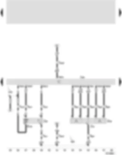
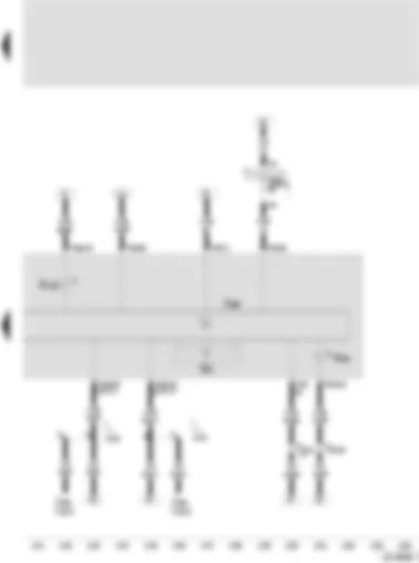
Wiring Diagram SEAT AROSA 2001 - Battery - starter - alternator - voltage regulator - ignition/starter switch - terminal 30 junction box - X contact relief relay

| A | Battery (00532) |
| B | Starter |
| C | Alternator |
| C1 | Voltage regulator |
| D | Ignition/starter switch |
| E1 | Lighting switch |
| E19 | Parking light switch |
| J59 | X contact relief relay |
| SA2 | Fuse -2- on battery fuse holder |
| SA1 | Fuse -1- on battery fuse holder |
| T5s | 5-pin connector, in the transmission |
| T10 | 10-pin connector, green, in interconnection station |
| T10a | 10-pin connector, red, in interconnection station |
| TV2 | Terminal 30 junction box |
| 1 | Earth strap, battery body |
| 2 | Earth strap, gearbox - body |
| 500 | Screw connection -1- (30), on relay plate |
| 501 | Screw connection -2- (30), on relay plate |
| 502 | Screw connection -1- (30a), on relay plate |
| A32 | Positive connection (30), in dash panel wiring harness |
| A40 | Positive connection -1- (30), in dash panel wiring harness |
| A41 | Positive (+) connection (50), in dash panel wiring harness |
| A61 | Positive connection (X), in dash panel wiring harness |
| B102 | Earth connection, in front left interior wiring harness |
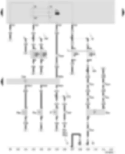
Wiring Diagram SEAT AROSA 2001 - Motronic control unit - ignition transformer - coolant temperature sender - plug cap - spark plugs
| G2 | Coolant temperature sender |
| G62 | Coolant temperature sender |
| J220 | Motronic control unit |
| N152 | Ignition transformer |
| P | Plug cap |
| Q | Spark plugs |
| SB24 | Fuse -24- in fusebox |
| SB30 | Fuse -30- in the fusebox |
| SB34 | Fuse -34- in the fusebox |
| SB36 | Fuse -36- in the fusebox |
| T10 | 10-way connector, green, in the wiring harness interconnection |
| T10d | 10-way connector, white, in the wiring harness interconnection |
| T10n | 10-way connector, grey, in the wiring harness interconnection |
| 10 | Plenum chamber earthing point |
| 220 | Earth connection (sender earth), engine wiring harness |
| A2 | Positive connection (15), instrument panel wiring harness |
| A104 | Positive connection -2- (15), dash panel insert wiring harness |
| * | Only on ANW and AUD vehicles with automatic gearbox |
| ** | Only on vehicles without automatic gearbox |
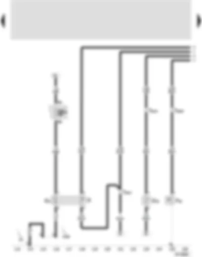
Wiring Diagram SEAT AROSA 2001 - Motronic control unit - PAS pressure switch - engine revolution sender - Hall sender - exhaust gas recirculation potentiometer - exhaust gas recirculation valve
| F88 | PAS pressure switch |
| G28 | Engine revolution sender |
| G40 | Hall sender |
| G212 | Exhaust gas recirculation potentiometer |
| J217 | Automatic gearbox control unit |
| J220 | Motronic control unit |
| J293 | Radiator fan control unit |
| N18 | Exhaust gas recirculation valve |
| T10c | 10-way connector, black, in the wiring harness interconnection |
| T10d | 10-way connector, white, in the wiring harness interconnection |
| T14 | 14-way connector, engine |
| T14a | 14-way connector, brown, engine |
| 220 | Earth connection (sender earth), engine wiring harness |
| A52 | Positive connection -2- (30), instrument panel wiring harness |
| D101 | Connection -1-, engine bay wiring harness |
| D161 | Connection (radiator fan run-on cycle), in the engine bay wiring harness |
| L5 | Connection-1-, air conditioning wiring harness |
| * | Only vehicles with air conditioning |
| ** | Only on ANW and AUD vehicles with automatic gearbox |
| *** | Only on ANW and AUD vehicles without automatic gearbox |
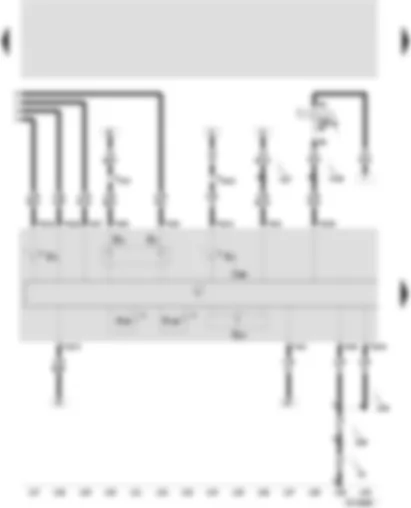
Wiring Diagram SEAT AROSA 2001 - Motronic control unit - inlet air temperature sender - inlet manifold pressure sender - accelerator position sender - sender -2- for the accelerator pedal position
| G42 | Inlet air temperature sender |
| G71 | Inlet manifold pressure sender |
| G79 | Accelerator pedal position sender |
| G185 | Sender -2- for the accelerator pedal position |
| J220 | Motronic control unit |
| T14 | 14-way connector, engine |
Wiring Diagram SEAT AROSA 2001 - Motronic control unit - throttle valve control unit - throttle valve control (electric accelerator control) - angle sender -1- for throttle valve (electric accelerator control)
| G186 | Throttle valve control (electric accelerator control) |
| G187 | Angle sender -1- for throttle valve control (electric accelerator control) |
| G188 | Angle sender -2- for throttle valve control (electric accelerator control) |
| J104 | Control unit for ABS with EDS |
| J217 | Automatic gearbox control unit |
| J220 | Motronic control unit |
| J338 | Throttle valve control unit |
| T10n | 10-way connector, grey, in the wiring harness interconnection |
| T14 | 14-way connector, engine |
| T14a | 14-way connector, brown, engine |
| 10 | Plenum chamber earthing point |
| 167 | Earth connection -4-, engine bay wiring harness |
| D159 | Connection (High-Bus), engine bay wiring harness |
| D160 | Connection (Low-Bus), engine bay wiring harness |
| * | Only on ANW and AUD vehicles with automatic gearbox |
| ** | Only on vehicles without automatic gearbox |
Wiring Diagram SEAT AROSA 2001 - Motronic control unit - knock sensor I - injector - cylinder 1 - injector - cylinder 2 - injector - cylinder 3 - injector - cylinder 4
| G61 | Knock sensor I (00524-2142) |
| J220 | Motronic control unit |
| J362 | Immobiliser control unit |
| N30 | Injector, cylinder 1 (01249-4411) |
| N31 | Injector, cylinder 2 (01250-4412) |
| N32 | Injector, cylinder 3 (01251-4413) |
| N33 | Injector, cylinder 4 (01252-4414) |
| T10 | 10-pin connector, green, in the interconnection station |
| T10a | 10-pin connector, red, in the interconnection station |
| T10b | 10-pin connector, blue in the interconnection station |
| T10n | 10-pin connector, grey, in the interconnection station |
| T14 | 14-pin connector, in the engine |
| T14a | 14-pin connector, brown, in the engine |
| 200 | Earthing connection (screened), in engine compartment wiring harness |
| D95 | Connection (injectors) in engine compartment wiring harness |
| * | Self-diagnosis wire W |
Wiring Diagram SEAT AROSA 2001 - Motronic control unit - lambda probe - lambda probe after catalyst - lambda probe heater - lambda probe heater 1 - after catalyst
| G39 | Lambda probe (00525-2342) |
| G130 | Lambda probe after catalyst (00699) |
| J220 | Motronic control unit |
| T10a | 10-pin connector, red, in the interconnection station |
| Z19 | Lambda probe heater |
| Z29 | Lambda probe heater 1, after catalyst |
| D102 | Connection -2-, in engine compartment wiring harness |
| E30 | Connection (87a), in engine wiring harness |
Wiring Diagram SEAT AROSA 2001 - Motronic control unit - fuel pump relay - brake light switch - brake pedal switch - speedometer sender - active charcoal filter system electrovalve 1
| F | Brake light switch |
| F63 | Brake pedal switch |
| G22 | Speedometer sender |
| J17 | Fuel pump relay |
| J220 | Motronic control unit |
| M9 | Brake light bulb, left |
| M10 | Brake light bulb, right |
| M25 | High level brake light bulb |
| N80 | Activated charcoal filter system solenoid valve I (pulsed) |
| T10 | 10-way connector, green, in the wiring harness interconnection |
| T10a | 10-way connector, red, in the wiring harness interconnection |
| T10c | 10-way connector, black, in the wiring harness interconnection |
| T10d | 10-way connector, white, in the wiring harness interconnection |
| T14 | 14-way connector, engine |
| 12 | Earth point in engine bay, on the left |
| 82 | Earth connection -1-, front left wiring harness |
| A2 | Positive connection (15), instrument panel wiring harness |
| A38 | Positive connection -2- (15a), in instrument panel wiring harness |
| A99 | Connection -1- (87), in the instrument panel wiring harness |
| D73 | Positive connection (54), engine bay wiring harness |
Wiring Diagram SEAT AROSA 2001 - Fuel level indicator sender - fuel pump (pre-supply pump) - coolant level indicator sender - oil pressure switch 0 -3 bar
| F22 | Oil pressure switch 0,3 bar |
| G | Fuel level sender |
| G6 | Fuel pump (pre-supply pump) |
| G32 | Coolant level sender |
| SB40 | Fuse -40- in the fusebox |
| T10a | 10-way connector, red, in the wiring harness interconnection |
| T10c | 10-way connector, black, in the wiring harness interconnection |
| 61 | Earth point, C strut left |
| B109 | Earth connection, interior wiring harness, rear left |
Wiring Diagram SEAT AROSA 2001 - Control unit with warning lamps on dash panel insert - fuel gauge - coolant temperature gauge - speedometer - oil pressure warning lamp -coolant temperature/level warning lamp
| G1 | Fuel gauge |
| G3 | Coolant temperature gauge |
| G21 | Speedometer |
| J285 | Control unit with warning lamps on instrument panel |
| K2 | Alternator warning lamp |
| K3 | Oil pressure warning lamp |
| K28 | Coolant temperature/level warning lamp |
| K105 | Fuel level indicator lamp |
| SB16 | Fuse -16- in the fusebox |
| T10 | 10-way connector, green, in the wiring harness interconnection |
| T10a | 10-way connector, red, in the wiring harness interconnection |
| 76 | Earth point, near gearbox control |
| 238 | Earth connection-1-, interior wiring harness |
| 249 | Earth connection -2-, interior wiring harness |
| A27 | Connection (speed signal), instrument panel wiring harness |
| B158 | Connection (S), interior wiring harness |
Wiring Diagram SEAT AROSA 2001 - Control unit with warning lamps in the dash panel - revolution counter - exhaust gas warning lamp (EOBD) - electronic accelerator control warning lamp (EPC)
| G5 | Rev. counter |
| J285 | Control unit with warning lamps on instrument panel |
| J362 | Immobilizer control unit |
| K83 | Exhaust gas warning lamp (EOBD) |
| K132 | Electric accelerator control warning lamp (EPC) |
| SB11 | Fuse -11- in the fusebox |
| T10n | 10-way connector, grey, in the wiring harness interconnection |
| A121 | Connection (High-Bus), instrument panel wiring harness |
| A122 | Connection (Low-Bus), instrument panel wiring harness |
Can't find your car? Check -> DiagnostData.com!


